change wheel MERCEDES-BENZ SLK250 2012 R172 Owner's Guide
[x] Cancel search | Manufacturer: MERCEDES-BENZ, Model Year: 2012, Model line: SLK250, Model: MERCEDES-BENZ SLK250 2012 R172Pages: 334, PDF Size: 4.26 MB
Page 190 of 334
Other status indicators of the
navigation system R
0002:y ou have reached the destination or an
intermediate destination.
R New Route... or
Calculating Route : a
new route is being calculated.
R Off Map or
Off Mapped Road :t
he vehicle
position is outside the area of the digital
map (off-map position).
R No Route :n
o route could be calculated to
the selected destination. Audio menu
Selecting aradio station i
SIRIUS XM satellite radio functions like a
normal radio.
For more information on satellite radio
operation, see the separate operating
instructions.
You can only change the waveband and store
new stations using Audio 20 or COMAND.
X Switch on Audio 20 or COMAND (see the
separate operating instructions) and select
Radio.
X Press the 0002or0005 button on the
steering wheel to select the Audio menu.
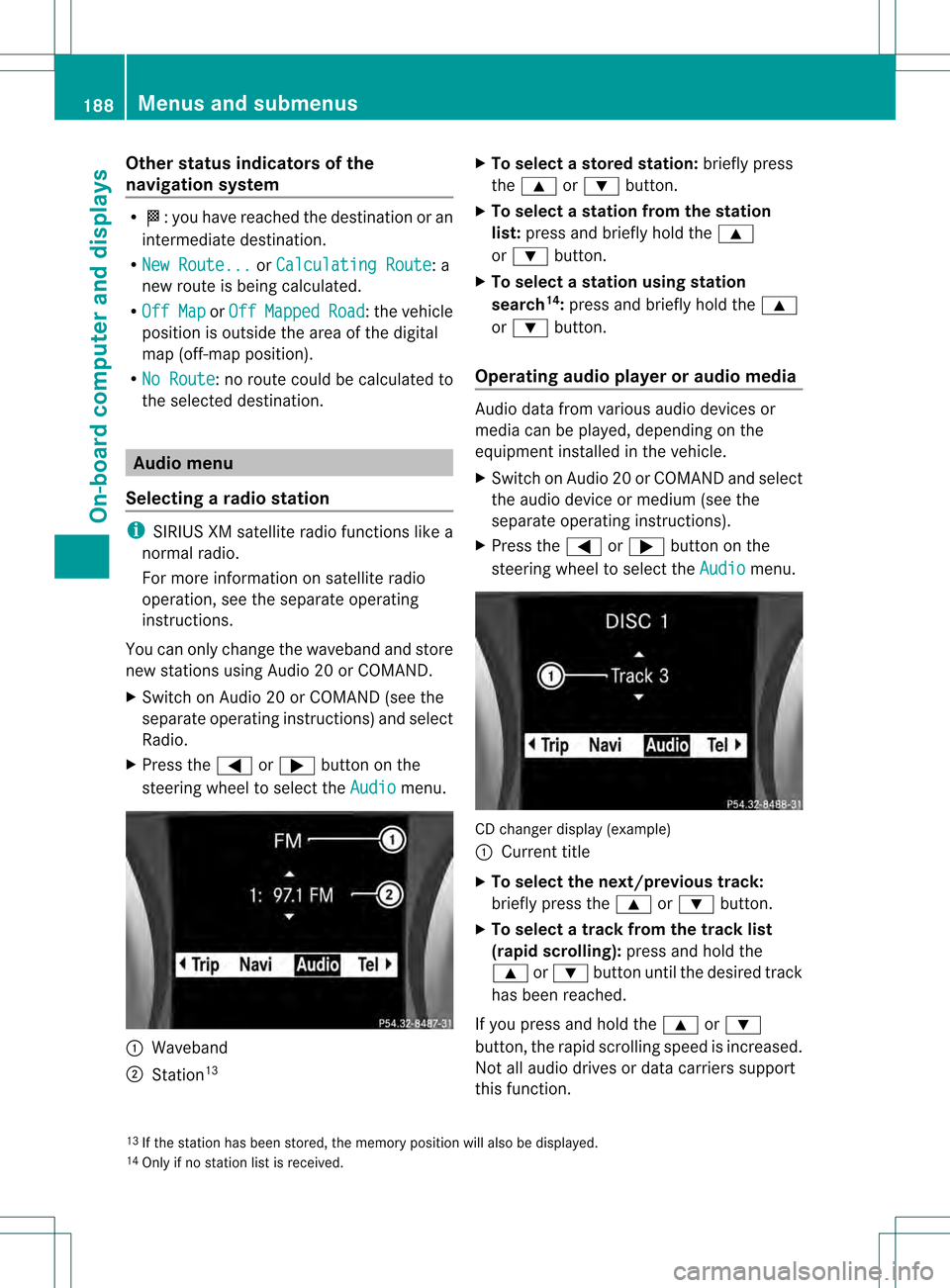
0002
Waveband
0003 Station 13 X
To selectas toredstation: briefly press
the 0003 or0004 button.
X To select a station from the station
list: press and briefly hold the 0003
or 0004 button.
X To select astation using station
search 14
:press and briefly hold the 0003
or 0004 button.
Operating audio player or audio media Audio data from various audi
odevices or
media can be played, depending on the
equipment installed in the vehicle.
X Switch on Audio 20 or COMAND and select
the audio device or medium (see the
separate operating instructions).
X Press the 0002or0005 button on the
steering wheel to select the Audio menu.
CD changer display (example)
0002
Current title
X To select the next/previous track:
briefly press the 0003or0004 button.
X To select a track from the track list
(rapid scrolling): press and hold the
0003 or0004 button until the desired track
has been reached.
If you press and hold the 0003or0004
button, the rapid scrollin gspeed is increased.
Not all audio drives or data carriers support
this function.
13 If the station has been stored, the memory position will also be displayed.
14 Only if no station list is received. 188
Menus and submenusOn-board computer and displays
Page 191 of 334
If track information is stored on the audio
device or medium, the multifunction display
will show the number and name of the track.
The current track does not appear in audio
AUX mode (Auxiliary audio mode: external
audio source connected).
Video DVD operation X
Switch on COMAND and select video DVD
(see the separate operating instructions).
X Press the 0002or0005 button on the
steering wheel to select the Audio menu.
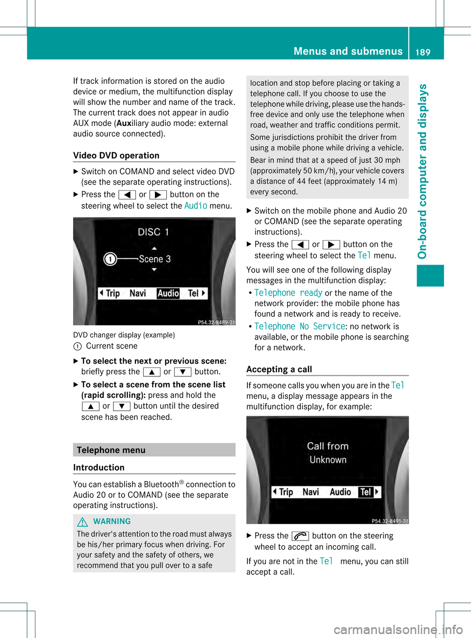
DVD changer display (example)
0002
Current scene
X To select the next or previous scene:
briefly press the 0003or0004 button.
X To select ascene from the scene list
(rapid scrolling): press and hold the
0003 or0004 buttonuntil the desired
scene has been reached. Telephone menu
Introduction You can establish a Bluetooth
®
connection to
Audio 20 or to COMAND (see the separate
operating instructions). G
WARNING
The driver's attentio nto the road must always
be his/her primary focus when driving. For
your safety and the safety of others, we
recommend that you pull over to a safe location and stop before placing or taking a
telephone call. If you choose to use the
telephone while driving, please use the hands-
free device and only use the telephone when
road, weather and traffic conditions permit.
Some jurisdictions prohibit the driver from
using a mobile phone while driving a vehicle.
Bear in mind that at a speed of just 30 mph
(approximately 50 km/h) , your vehicle covers
a distance of 44 feet (approximately 14 m)
every second.
X Switch on the mobile phone and Audio 20
or COMAN D(see the separate operating
instructions).
X Press the 0002or0005 button on the
steering wheel to select the Tel menu.
You will see one of the following display
messages in the multifunction display:
R Telephone ready or the name of the
network provider: the mobile phone has
found a network and is ready to receive.
R Telephone No Service : no network is
available, or the mobile phone is searching
for a network.
Accepting acall If someone calls you whe
nyou are in the Tel menu, a display message appears in the
multifunction display, for example:
X
Press the 0005button on the steering
wheel to accept an incoming call.
If you are not in the Tel menu, you can still
accept a call. Menus and submenus
189On-board computer and displays Z
Page 225 of 334
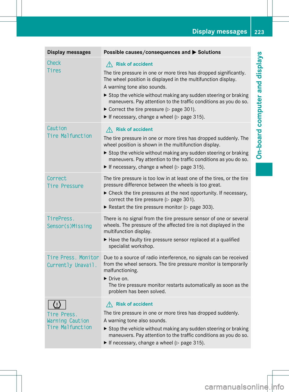
Display messages Possible causes/consequences and
0001 Solutions
Check
Tires G
Risk of accident
The tire pressure in one or more tires has dropped significantly.
The wheel position is displayed in the multifunction display.
Aw arning tone also sounds.
X Stop the vehicle without making any sudde nsteering or braking
maneuvers. Pay attentio nto the traffic conditions as you do so.
X Correct the tire pressure (Y page 301).
X If necessary, change a wheel (Y page 315).Caution
Tire Malfunction G
Risk of accident
The tire pressure in one or more tires has dropped suddenly. The
wheel position is shown in the multifunction display.
X Stop the vehicle without making any sudden steering or braking
maneuvers. Pay attention to the traffic conditions as you do so.
X If necessary, change a wheel (Y page 315).Correct
Tire Pressure The tire pressure is too low in at least one of the tires, or the tire
pressure difference between the wheels is too great.
X Check the tire pressures at the next opportunity. If necessary,
correct the tire pressure (Y page 301).
X Restart the tire pressure monitor (Y page 303).TirePress.
Sensor(s)Missing There is no signal from the tire pressure sensor of one or several
wheels. The pressure of the affected tire is not displayed in the
multifunction display.
X
Have the faulty tire pressure sensor replaced at a qualified
specialist workshop. Tire Press. Monitor
Currently Unavail. Due to a source of radio interference, no signals can be received
from the wheel sensors. The tire pressure monitor is temporarily
malfunctioning.
X
Drive on.
The tire pressure monitor restarts automatically as soon as the
problem has been solved. 0015
Tire Press.
Warning Caution
Tire Malfunction G
Risk of accident
The tire pressure in one or more tires has dropped suddenly.
Aw arning tone also sounds.
X Stop the vehicle without making any sudde nsteering or braking
maneuvers. Pay attentio nto the traffic conditions as you do so.
X If necessary, change a wheel (Y page 315). Display messages
223On-board computer and displays Z
Page 226 of 334
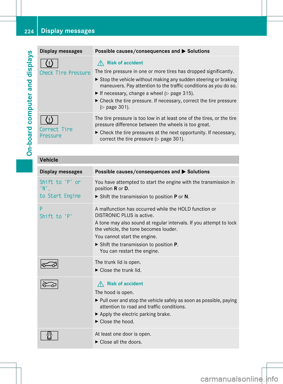
Display messages Possible causes/consequences and
0001 Solutions
0015
Check
Tire Pressure G
Risk of accident
The tire pressure in one or more tires has dropped significantly.
X Stop the vehicle without making any sudden steering or braking
maneuvers .Pay attentio nto the traffic conditions as you do so.
X If necessary, change a wheel (Y page 315).
X Check the tire pressure. If necessary, correct the tire pressure
(Y page 301). 0015
Correct Tire
Pressure The tire pressure is too low in at least one of the tires, or the tire
pressure difference between the wheels is too great.
X
Check the tire pressures at the next opportunity. If necessary,
correct the tire pressure (Y page 301).Vehicle
Display messages Possible causes/consequences and
0001 Solutions
Shift to 'P' or
'N',
to Start Engine You have attempted to start the engine with the transmission in
position
Ror D.
X Shift the transmission to position Por N. P
Shift to 'P' A malfunction has occurred while the HOLD function or
DISTRONIC PLUS is active.
At
one may also sound at regular intervals. If you attempt to lock
the vehicle, the tone becomes louder.
You cannot start the engine.
X Shift the transmission to position P.
You can restart the engine. 0013 The trunk lid is open.
X
Close the trunk lid. 0012 G
Risk of accident
The hood is open.
X Pull over and stop the vehicle safely as soon as possible, paying
attention to road and traffic conditions.
X Apply the electric parking brake.
X Close the hood. 0004 At least one door is open.
X
Close all the doors. 224
Display messagesOn-board computer and displays
Page 240 of 334
Tires
Problem Possible causes/consequences and
0001 Solutions
0015
USA only:
The yellow tire pressure
monitor warning lamp
(pressure loss/
malfunction) is lit.
Canada only:
The yellow tire pressure
monitor warning lamp
(pressure loss) is lit.
G
Ris
kofa ccident
The tire pressure monito rhas detected a loss of pressure in at
least one of the tires.
X Stop the vehicle without making any sudde nsteering or braking
maneuvers. Pay attentio nto the traffic conditions as you do so.
X Observe the additional display messages in the multifunction
display.
X Check the tire pressure. If necessary, correct the tire pressure
(Y page 301).
X If necessary, change a wheel (Y page 315).0015
USA only:
The yellow tire pressure
monitor warning lamp
(pressure loss/
malfunction) flashes for
approximately one
minute and then
remains lit.
The tire pressure monitor is faulty.
X
Observe the additional display messages in the multifunction
display.
X Visit a qualified specialist workshop. G
WARNING
Each tire, including the spare (if provided), should be checked at least once every two weeks
when cold and inflated to the pressure recommended by the vehicle manufacturer on the Tire
and Loading Information placard on the driver's side B-pillar or the tire pressure label on the
inside of the fuel filler flap. If your vehicle has tires of a different size than the size indicated on
the Tire and Loading Information placard or, if available, the tire pressure label, you should
determine the proper tire pressure for those tires.
As an added safety feature, your vehicle has been equipped with a tire pressure monitoring
system (TPMS) that illuminates a low tire pressure indicator lamp when one or more of your tires
are significantly underinflated. Accordingly, when the low tire pressure telltale illuminates, you
should stop and check your tires as soon as possible, and inflate them to the proper pressure.
Driving on a significantly underinflated tire causes the tire to overheat and can lead to tire failure.
Underinflation also reduces fuel efficiency and tire tread life, and may affect the vehicle's handling
and stopping ability. Please note that the TPMS is not a substitute for proper tire maintenance,
and it is the driver's responsibility to maintain correc ttire pressure, even if underinflation has
not reached the level to trigger illumination of the TPMS low tire pressure indicator lamp.
USA only:
Your vehicle has also been equipped with a TPMS malfunction indicator to indicate when the
system is not operating properly. The TPMS malfunction indicator is combined with the low tire
pressure telltale. When the system detects a malfunction, the indicator lamp will flash for 238
Warning and indicator lamps in the instrument clusterOn-board computer and displays
Page 253 of 334
Response Cente
rwill automatically contact
local emergency officials with the vehicle's
approximate location if they receive an
automatic SOS signal and cannot make voice
contact with the vehicle occupants.
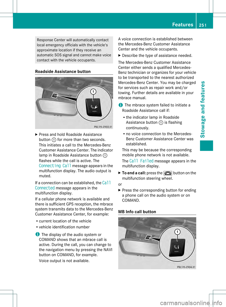
Roadside Assistance button X
Press and hold Roadside Assistance
button 0002for more than two seconds.
This initiates a call to the Mercedes-Benz
Customer Assistance Center. The indicator
lamp in Roadside Assistance button 0002
flashes while the call is active. The
Connecting Call message appears in the
multifunction display. The audio output is
muted.
If a connection can be established, the CallConnected message appears in the
multifunction display.
If a cellular phone network is available and
there is sufficient GPS reception, the mbrace
system transmits data to the Mercedes-Benz
Customer Assistance Center, for example:
R current location of the vehicle
R vehicle identification number
i The display of the audio system or
COMAND shows that an mbrace call is
active. During the call, you can change to
the navigation menu by pressing the NAVI
button on COMAND, for example.
Voice output is not available. Av
oice connection is established between
the Mercedes-Benz Customer Assistance
Center and the vehicle occupants.
X Describe the type of assistance needed.
The Mercedes-Benz Customer Assistance
Center either sends a qualified Mercedes-
Benz technician or organizes for your vehicle
to be transported to the nearest authorized
Mercedes-Benz Center. You may be charged
for services such as repair work and/or
towing. Further details are available in your
mbrace manual.
i The mbrace system failed to initiate a
Roadside Assistance call if:
R the indicator lamp in Roadside
Assistance button 0002is flashing
continuously.
R no voice connection to the Mercedes-
Benz Customer Assistance Center was
established.
This may be because the corresponding
mobile phone network is not available.
The Call Failed message appears in the
multifunction display.
X To end acall: press the 0004button on the
multifunctio nsteering wheel.
or
X Press the corresponding button for ending
a phone call on the audio syste moron
COMAND.
MB Info call button Features
251Stowage and featu res Z
Page 254 of 334
X
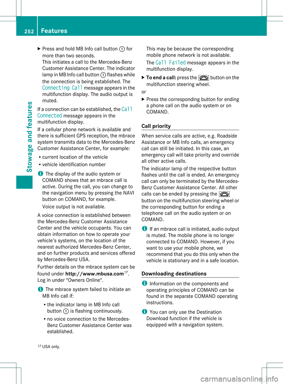
Press and hold MB Info call button 0002for
more than two seconds.
This initiates a call to the Mercedes-Benz
Customer Assistance Center. The indicator
lamp in MB Info call button 0002flashes while
the connection is being established. The
Connecting Call message appears in the
multifunction display. The audio output is
muted.
If a connection can be established, the CallConnected message appears in the
multifunction display.
If a cellular phone network is available and
there is sufficient GPS reception, the mbrace
system transmits data to the Mercedes-Benz
Customer Assistance Center, for example:
R current location of the vehicle
R vehicle identification number
i The display of the audio system or
COMAND shows that an mbrace call is
active. During the call, you can change to
the navigation menu by pressing the NAVI
button on COMAND, for example.
Voice output is not available.
Av oice connection is established between
the Mercedes-Benz Customer Assistance
Center and the vehicle occupants. You can
obtain information on how to operate your
vehicle's systems, on the location of the
nearest authorized Mercedes-Benz Center,
and on further products and services offered
by Mercedes-Benz USA.
Further details on the mbrace system can be
found under http://www.mbusa.com 17
.
Log in under "Owners Online".
i The mbrace system failed to initiate an
MB Info call if:
R the indicator lamp in MB Info call
button 0002is flashing continuously.
R no voice connection to the Mercedes-
Benz Customer Assistance Center was
established. This may be because the corresponding
mobile phone network is not available.
The Call Failed message appears in the
multifunction display.
X To end acall: press the 0004button on the
multifunctio nsteering wheel.
or
X Press the corresponding button for ending
a phone call on the audio syste moron
COMAND.
Call priority When service calls are active, e.g. Roadside
Assistance or MB Info calls, an emergency
call can still be initiated. In this case, an
emergency call will take priority and override
all other active calls.
The indicator lamp of the respective button
flashes until the call is ended. An emergency
call can only be terminated by the Mercedes-
Benz Customer Assistance Center. All other
calls can be ended by pressing the 0004
butto nont he multifunction steering wheel or
the corresponding button for ending a
telephone call on the audio system or on
COMAND.
i If an mbrace call is initiated, audio output
is muted. The mobile phone is no longer
connected to COMAND. However, if you
want to use your mobile phone, we
recommend that you do this only when the
vehicle is stationary and in a safe location.
Downloading destinations i
Information on the components and
operating principles of COMAND can be
found in the separate COMAND operating
instructions.
i You can only use the Destination
Download function if the vehicle is
equipped with a navigation system.
17 USA only. 252
FeaturesStowage and features
Page 272 of 334
X
Wipe the plastic trim with a damp, lint-free
cloth, e.g. a microfiber cloth.
X Heavy soiling: use car care and cleaning
products recommended and approved by
Mercedes-Benz.
The surface may change color temporarily.
Wait until the surface is dry again.
Cleaning the steering wheel and gear or
selector lever X
Thoroughly wipe with a damp cloth or use
leather care agents that have been
recommended and approved by Mercedes-
Benz.
Cleaning genuine wood and trim
elements X
Wipe the wooden trim and trim pieces with
a damp, lint-free cloth ,e.g. a microfiber
cloth.
X Heavy soiling: use car care and cleaning
products recommended and approved by
Mercedes-Benz.
! Do not use solvent-based cleaning agents
such as tar remover, whee lcleaners,
polishes or waxes. There is otherwise a risk
of damaging the surface.
! Do not use chrome polish on trim pieces.
The trim pieces have a chrome look but are
mostly made of anodized aluminum and
can lose their shine if chrome polish is
used. Use a damp, lint-free cloth instead
when cleaning the trim pieces.
If the chrome-plated trim pieces are very
dirty, you can use a chrome polish. If you
are unsure as to whether the trim pieces
are chrome-plated or not, consult an
authorized Mercedes-Ben zCenter.
Cleaning the seat covers !
Do not use microfiber cloths to clean
genuine leather, artificial leather or
Alcantara® covers. If used often, these can
damage the cover. !
Observe the following when cleaning:
R clean genuine leather cover scarefully
with a damp cloth and then wipe the
covers down with a dry cloth .Make sure
that the leather does no tbecome
soaked. It may otherwise become rough
and cracked. Only use leather care
agents that have been tested and
approved by Mercedes-Benz. You can
obtain these from a qualified specialist
workshop.
R clean artificial leather covers with a cloth
moistened with a solution containing 1%
detergen t(e.g. dish washing liquid).
R clean cloth covers with a microfiber cloth
moistened with a solution containing 1%
detergen t(e.g. dish washing liquid). Rub
carefully and always wipe entire seat
sections to avoid leaving visible lines.
Leave the seat to dry afterwards.
Cleaning results depend on the type of
dirt and how long it has been there.
R clean Alcantara® covers with a damp
cloth. Make sure that you wipe entire
seat sections to avoid leaving visible
lines.
i Note that regular care is essential to
ensure that the appearance and comfort of
the covers is retained over time.
Cleaning the seat belts X
Use clean, lukewarm water and soap
solution.
! Do not clean the seat belts using chemical
cleaning agents .Do not dry the seat belts
by heating at temperatures above 176 ‡
(80 †) or in direct sunlight. G
WARNING
Do not bleach or dye seat belts as this may
severely weaken them. In a crash, they may
not be able to provide adequate protection. 270
CareMaintenance and care
Page 278 of 334
X
Apply the electri cparking brake manually
(Y page 150).
X Bring the fron twheels into the straight-
ahead position.
X Move the selector lever to position P.
X Switch off the engine.
X Vehicles without KEYLESS-GO: remove
the SmartKey from the ignition lock.
X Vehicles with KEYLESS-GO: open the
driver's door.
The on-board electronics have status 0,
which is the same as the SmartKey having
been removed.
X Vehicles with KEYLESS-GO: remove the
Start/Stop button from the ignition lock
(Y page 131).
X All occupants must get out of the vehicle.
Make sure that they are not endangered as
they do so.
X Make sure that no one is near the danger
area while a wheel is being changed.
Anyone who is not directly assisting in the
wheel change should, for example, stand
behind the barrier.
X Get out of the vehicle. Pay attention to
traffic conditions when doing so.
X Close the driver's door. Changing
awheel and mounting the
spare wheel
Preparing the vehicle When using a different size spare wheel or
emergency spare wheel, do not exceed the
maximum road speed of 50 mph (80 km/h)
G
WARNING
The wheel or tire size as well as the tire type
of the spare wheel or emergency spare wheel
and the wheel to be replaced may differ.
Mounting an emergency spare wheel may
severely impair the driving characteristics.
There is a risk of an accident. To avoid hazardous situations:
R
adapt you rdriving style accordingly and
drive carefully.
R never install more than one spare wheel or
emergency spare wheel that differs in size.
R only use a spare wheel or emergency spare
wheel of a different size briefly.
R do not switch ESP ®
off.
R have a spare wheel or emergency spare
wheel of a different size replaced at the
nearest qualified specialist workshop.
Observe that the wheel and tire dimensions
as well as the tire type must be correct.
i Vehicles withou taspare wheel or
emergency spare wheel are not equipped
with a tire-change tool kit at the factory. For
more information on which tools are
required to perform a wheel change on your
vehicle, e.g. wheel chock, lug wrench or
alignment bolt, consult an authorized
Mercedes-Benz Center.
X Prepare the vehicle as described
(Y page 275).
X Remove the following items (depending on
the vehicle's equipment) from the stowage
well under the trunk floor:
R
emergency spare wheel
R lug wrench
R folding wheel chock
R jack
R alignment bolt
R tire inflation compressor
X Secure the vehicle to prevent it from rolling
away.
Securing the vehicle to prevent it from
rolling away If your vehicle is equipped with a wheel chock,
it can be found in the vehicle tool kit
(Y
page 274).
The folding wheel chock is an additional
securing measure to prevent the vehicle from 276
Flat tireBreakdown assistance
Page 279 of 334

rolling away, for example when changing a
wheel.
X
Fold both plates upwards 0002.
X Fold out lower plate 0003.
X Guide the lugs on the lower plate fully into
the openings in base plate 0023.Securing the vehicle on level ground
X
On level ground: place chocks or other
suitable items under the front and rear of
the wheel that is diagonally opposite the
wheel you wish to change. Securing the vehicle on slight downhill gradients X
On downhill gradients: place chocks or
other suitable items in front of the wheels
of the front and rear axle.
Raising the vehicle G
WARNING
If you do not position the jack correctly at the
appropriate jacking point of the vehicle, the
jack could tip over with the vehicle raised.
There is a risk of injury.
Only position the jack at the appropriate
jacking point of the vehicle. The base of the
jack must be positioned vertically, directly
under the jacking point of the vehicle.
The following must be observed when raising
the vehicle:
R to raise the vehicle, only use the vehicle-
specific jack that has been tested and
approved by Mercedes-Benz. If used
incorrectly, the jack could tip over with the
vehicle raised.
R the jack is designed only to raise and hold
the vehicle for a short time while a wheel
is being changed .Itis not suited for
performing maintenance work under the
vehicle.
R avoid changing the wheel on uphill and
downhill slopes.
R before raising the vehicle, secure it from
rolling away by applying the parking brake
and inserting wheel chocks. Never
disengage the parking brake while the
vehicle is raised.
R the jack must be placed on a firm, flat and
non-slip surface. On a loose surface, a
large, load-bearing underlay must be used.
On a slippery surface, a non-slip underlay
must be used, e.g. rubber mats.
R do not use wooden blocks or similar
objects as a jack underlay.O therwise, the
jac kw ill not be able to achieve its load-
bearing capacity due to the restricted
height. Flat tire
277Breakdown assistance Z