clock MERCEDES-BENZ SLS COUPE 2010 Owners Manual
[x] Cancel search | Manufacturer: MERCEDES-BENZ, Model Year: 2010, Model line: SLS COUPE, Model: MERCEDES-BENZ SLS COUPE 2010Pages: 361, PDF Size: 6.32 MB
Page 62 of 361
Function Page
000E
Selects a statio
nusing the
station search function 162
Rewind 176,
194 Selects the previous track 176
000F
PIN confirmation (conveni-
ence telephony*)
133
Accepts a call 144
Dials a number 144
Redials 145
Accepts a waiting call 146
0010
Calls up the system menu 71
0011
Calls up the telephone
basic menu:
• Bluetooth
®
interface tel-
ephony 132
• Convenience telephony*
133 Function Page
0016
Rejects a call 144
Ends an active call 146
Rejects a waiting call 146
0017
Mute 67
Switches the hands-free
microphone on/off
146
Cancels the text message*
read-aloud function
148
Switches off the traffic and
navigation announcements
67
0018
Switches to navigation
mode
82
To show the menu 83
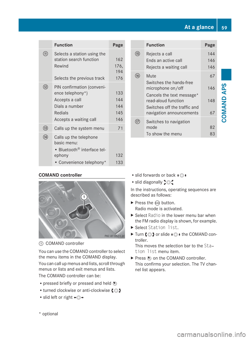
COMAND controller
0001
COMAND controller
You can use the COMAND controller to select
the menu items in the COMAND display.
You can call up menus and lists, scroll through
menus or lists and exit menus and lists.
The COMAND controller can be:
R pressed briefly or pressed and held 0017
R turned clockwise or anti-clockwise 002800130029
R slid left or right 002B0013002C R
slid forwards or back 001F0013000D
R slid diagonally 002A00130027
In the instructions, operating sequences are
described as follows:
X Press the 0006button.
Radio mode is activated.
X Select Radioin the lower menu bar when
the FM radio display is shown, for example.
X Select Station list.
X Turn 002800130029 or slide 001F0013000Dthe COMAND con-
troller.
This moves the selection bar to the Sta‐
tion list menu item.
X Press 0017on the COMAND controller.
This confirms your selection. The TV chan-
nel list appears. At
ag lance
59COMAND APS
*optional
BA 197 ECE RE 2010/6a; 1; 2, en-GB
sabbaeu Version: 3.0.3.6 2010-05-07T14:19:43+02:00 - Seite 59 Z
Page 76 of 361
Clock format:
R
HH -hour
R MM - minute
This setting applies for both the 24-hour
and the AM/PM format.
X To change the format: turn002800130029 or slide
001F0013000D.
X To confirm the change: press0017.
Setting the time zone and switching
between summer and standard time i
The correct time zone and summer/
standard time must be set for the following
navigation system functions to operate cor-
rectly:
R route guidance on routes with time-
dependent traffic guidance
R calculation of expected time of arrival
X To set the time zone: Sys‐
tem0004Time0004Time zone.
The country list appears. The 0023dot indi-
cates the current setting.
X Select the country in which you are cur-
rently driving.
Depending on the country you select, a
time zone list may also appear.
X Select the desired time zone.
Subsequent operation depends on:
R whether your navigation system has GPS
reception
R the country you have previously selected
You may either:
R switch between Summer timeandStand‐
ard time manually in a list
or
R switch automatic summer to standard time
changeover (and vice versa) on or off
X To switch manually: selectSummer
time orStandard time.
The 0023dot indicates the current setting. X
To switch automatic changeover on/
off: select Autom. Summer / Winter
time on orAutom. Summer / Winter
time off.
The 0023dot indicates the current setting.
X To store the setting and exit the menu:
press 0017.
X To exit the menu without saving: press
the 0001 back button next to the COMAND
controller or slide 002B0013002C.
i If you have switched off the automatic
changeover function, you must change
from summer to standard time and vice
versa manually using the "Set time" func-
tion (Y page 72). Read-aloud settings
Setting the read-aloud speed X
Select System0004Settings0004Text
reader speed.
The list of possible settings appears. The
0023 dot indicates the current setting.
X To select asetting: turn002800130029 or slide
001F0013000D .
X To confir myour selection: press0017. LINGUATRONIC settings
Activating/deactivating the help win-
dow X
Select System 0004Settings 0004Lingua‐
tronic .
X Select Help window .
You have switched the help window on
0019 or off 0004. System settings
73COMAND APS
BA 197 ECE RE 2010/6a; 1; 2, en-GB
sabbaeuV ersion: 3.0.3.6
2010-05-07T14:19:43+02:00 - Seite 73 Z
Page 86 of 361
Showing/hiding the menu system
X
To hide: slide001F0013and press 0017when the
Full screen menu item is shown.
or
X Press the 0001back button next to the
COMAND controller.
The menu system is hidden. The map can
be seen in the full-screen display.
X To show: press0017in the full-screen map
display. Map functions
Adjusting the map scale i
It is only possible to adjust the map scale
with the menu system hidden (full-screen
map display).
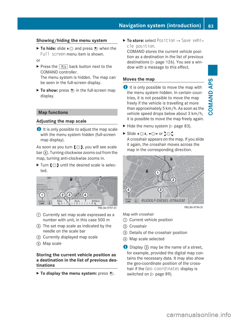
As soon as you turn 002800130029, you will see scale
bar 0014.T urning clockwise zooms out from the
map, turning anti-clockwise zooms in.
X Turn 002800130029 until the desired scale is selec-
ted. 0001
Currently set map scale expressed as a
number with unit, in this case 500 m
0002 The set map scale as indicated by the
needle on the scale bar
0015 Currently displayed map scale
0014 Map scale
Storing the curren tvehicle position as
ad estination in the list of previous des-
tinations X
To display the menu system: press0017. X
To store: selectPosition0004 Save vehi‐
cle position.
COMAND stores the curren tvehicle posi-
tion as a destination in the list of previous
destinations (Y page 126). You see a win-
dow with a message to this effect.
Moves the map i
It is only possible to move the map with
the menu system hidden. In certain coun-
tries, it is not possible to move the map
freely if the vehicle is travelling at more
than approximately 5km/h. As soon as the
vehicle speed drops below about 3km/h,
it is possible to move the map freely again.
X Hide the menu system (Y page 83).
X Slide 001F0013000D, 002B0013002Cor002A00130027.
Ac rosshair appears on the map. If you slide
it again, the crosshair moves across the
map in the corresponding direction. Map with crosshair
0001
Current vehicle position
0002 Crosshair
0015 Details of the crosshair position
0014 Map scale selected
i Display 0015may be the name of a street,
for example, provided the digital map con-
tains the necessary data .Itmay also show
the geo-coordinate positio nofthe cross-
hair if the Geo-coordinates display is
switched on (Y page 89). Navigation system (introduction)
83COMAND APS
BA 197 ECE RE 2010/6a; 1; 2, en-GB
sabbaeu Version: 3.0.3.6 2010-05-07T14:19:43+02:00 - Seite 83 Z
Page 90 of 361
X
Show the menu system (Y page 83).
X Select Navi0004Block area.
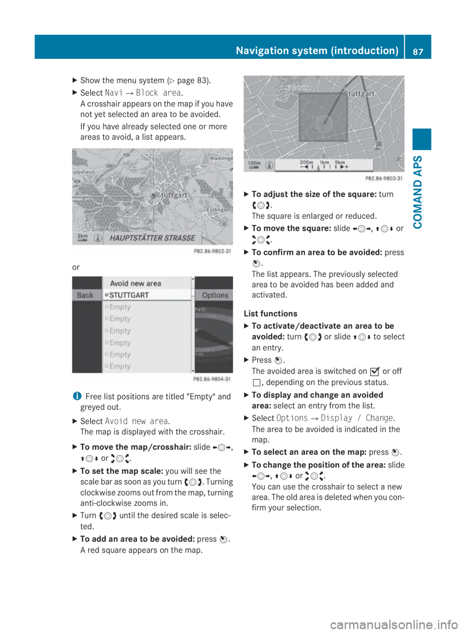
Ac rosshair appears on the map if you have
not yet selected an area to be avoided.
If you have already selected one or more
areas to avoid, a list appears. or
i
Free list positions are titled "Empty" and
greyed out.
X Select Avoid new area.
The map is displayed with the crosshair.
X To move the map/crosshair: slide002B0013002C,
001F0013000D or002A00130027.
X To set the map scale: you will see the
scale bar as soon as you turn 002800130029. Turning
clockwise zooms out from the map, turning
anti-clockwise zooms in.
X Turn 002800130029 until the desired scale is selec-
ted.
X To add an area to be avoided: press0017.
Ar ed square appears on the map. X
To adjust the size of the square: turn
002800130029.
The square is enlarged or reduced.
X To move the square: slide002B0013002C, 001F0013000Dor
002A00130027.
X To confirm an area to be avoided: press
0017.
The list appears. The previously selected
area to be avoided has been added and
activated.
List functions
X To activate/deactivate an area to be
avoided: turn002800130029 or slide 001F0013000Dto select
an entry.
X Press 0017.
The avoided area is switched on 0019or off
0004, depending on the previous status.
X To display and change an avoided
area: select an entry from the list.
X Select Options 0004Display / Change.
The area to be avoided is indicated in the
map.
X To select an area on the map: press0017.
X To change the position of the area: slide
002B0013002C, 001F0013000Dor002A00130027.
You can use the crosshair to select a new
area. The old area is deleted when you con-
firm your selection. Navigation system (introduction)
87COMAND APS
BA 197 ECE RE 2010/6a; 1; 2, en-GB
sabbaeu Version: 3.0.3.6 2010-05-07T14:19:43+02:00 - Seite 87 Z
Page 107 of 361
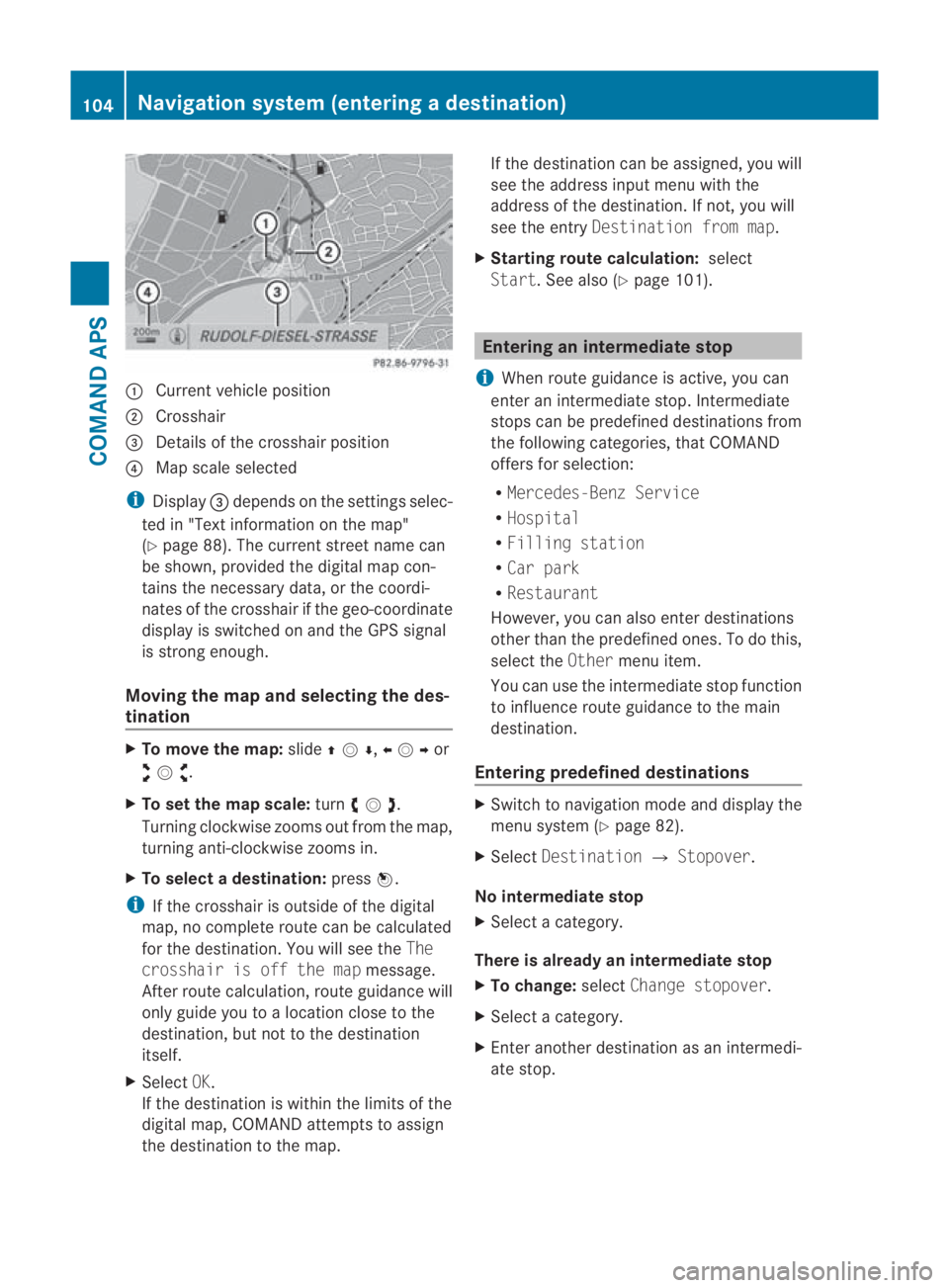
0001
Curren tvehicle position
0002 Crosshair
0015 Details of the crosshair position
0014 Map scale selected
i Display 0015depends on the settings selec-
ted in "Text information on the map"
(Y page 88). The current street name can
be shown, provided the digital map con-
tains the necessary data, or the coordi-
nates of the crosshair if the geo-coordinate
display is switched on and the GPS signal
is strong enough.
Moving the map and selecting the des-
tination X
To move the map: slide001F0013000D ,002B0013002Cor
002A00130027 .
X To set the map scale: turn002800130029 .
Turning clockwise zooms out from the map,
turning anti-clockwise zooms in.
X To select adestination: press0017.
i If the crosshair is outside of the digital
map, no complete route can be calculated
for the destination .You will see the The
crosshair is off the map message.
After route calculation, route guidance will
only guide you to a location close to the
destination, but not to the destination
itself.
X Select OK.
If the destination is within the limits of the
digital map, COMAND attempts to assign
the destination to the map. If the destination can be assigned, you will
see the address input menu with the
address of the destination .Ifnot, you will
see the entry Destination from map.
X Starting route calculation: select
Start.S ee also (Y page 101). Entering an intermediate stop
i When route guidance is active, you can
enter an intermediate stop. Intermediate
stops can be predefined destinations from
the following categories, that COMAND
offers for selection:
R Mercedes-Benz Service
R Hospital
R Filling station
R Car park
R Restaurant
However, you can also enter destinations
other than the predefined ones. To do this,
select the Othermenu item.
You can use the intermediate stop function
to influence route guidance to the main
destination.
Entering predefined destinations X
Switch to navigation mode and display the
menu system (Y page 82).
X Select Destination 0004Stopover.
No intermediate stop
X Select a category.
There is already an intermediate stop
X To change: selectChange stopover.
X Select a category.
X Enter another destination as an intermedi-
ate stop. 104
Navigation system (entering
adestination)COMAND APS
BA 197 ECE RE 2010/6a; 1; 2, en-GB
sabbaeu Version: 3.0.3.6
2010-05-07T14:19:43+02:00 - Seite 104
Page 121 of 361
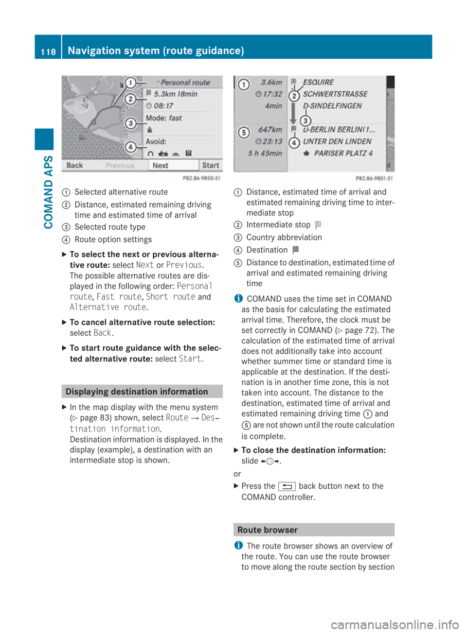
0001
Selected alternative route
0002 Distance, estimated remaining driving
time and estimated time of arrival
0015 Selected route type
0014 Route option settings
X To select the next or previous alterna-
tive route: selectNextorPrevious.
The possible alternative routes are dis-
played in the following order: Personal
route, Fast route, Short route and
Alternative route.
X To cancel alternative route selection:
select Back.
X To start route guidance with the selec-
ted alternative route: selectStart. Displaying destination information
X In the map display with the menu system
(Y page 83) shown, select Route0004Des‐
tination information.
Destination information is displayed .Inthe
display (example), a destination with an
intermediate stop is shown. 0001
Distance, estimated time of arrival and
estimated remaining driving time to inter-
mediate stop
0002 Intermediate stop 000C
0015 Country abbreviation
0014 Destination 000B
0012 Distance to destination, estimated time of
arrival and estimated remaining driving
time
i COMAND uses the time set in COMAND
as the basis for calculating the estimated
arrival time. Therefore, the clock must be
set correctly in COMAND (Y page 72). The
calculation of the estimated time of arrival
does not additionally take into account
whether summer time or standard time is
applicable at the destination. If the desti-
nation is in another time zone, this is not
taken into account. The distance to the
destination, estimated time of arrival and
estimated remaining driving time 0001and
0012 are not shown until the route calculation
is complete.
X To close the destination information:
slide 002B0013002C.
or
X Press the 0001back button next to the
COMAND controller. Route browser
i The route browser shows an overview of
the route. You can use the route browser
to move along the route section by section 118
Navigation system (route guidance)COMAND APS
BA 197 ECE RE 2010/6a; 1; 2, en-GB
sabbaeu
Version: 3.0.3.6 2010-05-07T14:19:43+02:00 - Seite 118
Page 123 of 361
X
To switch off: set theFast route or
Short route route type.
Proceed as described in the "Setting the
route type" section.
i COMAND calculates a new route if you
change the route type setting with route
guidance active. If you change the route
type setting when route guidance is inac-
tive, COMAND uses the new setting for the
next route guidance. RDS-TMC displays on the map
COMAND can show certain traffic incidents
on the map. These displays can be see non
map scales from 50 m (0.05 miles) up to
20 km (20 miles).
X To set the map scale: turn002800130029until the
desired map scale is set.
Turning clockwise zooms out from the map,
turning anti-clockwise zooms in. Example display of a traffic jam on the route
i COMAND uses corresponding icons to
highlight the entire section of the affected
route, regardless of how lon gthe incident
actually is. The icons are placed on the lane
affected by the incident.
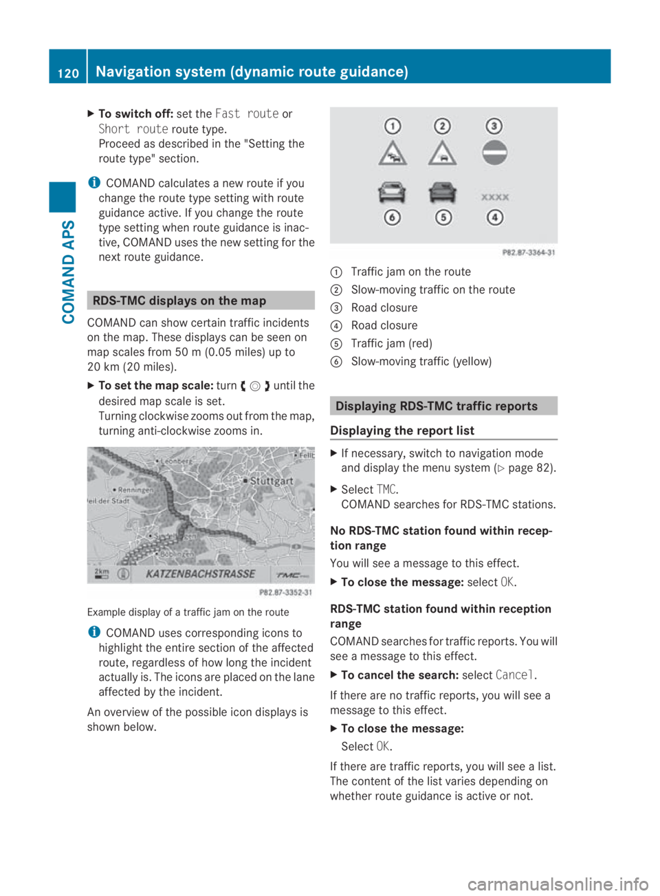
An overview of the possible icon displays is
shown below. 0001
Traffic jam on the route
0002 Slow-moving traffic on the route
0015 Road closure
0014 Road closure
0012 Traffic jam (red)
0013 Slow-moving traffic (yellow) Displaying RDS-TMC traffic reports
Displaying the report list X
If necessary, switch to navigation mode
and display the menu system (Y page 82).
X Select TMC.
COMAND searches for RDS-TMC stations.
No RDS-TMC station found within recep-
tion range
You will see a message to this effect.
X To close the message: selectOK.
RDS-TMC station found within reception
range
COMAND searches for traffic reports. You will
see a message to this effect.
X To cancel the search: selectCancel.
If there are no traffic reports, you will see a
message to this effect.
X To close the message:
Select OK.
If there are traffic reports, you will see a list.
The content of the list varies depending on
whether route guidance is active or not. 120
Navigation system (dynamic route guidance)COMAND APS
BA 197 ECE RE 2010/6a; 1; 2, en-GB
sabbaeu
Version: 3.0.3.6 2010-05-07T14:19:43+02:00 - Seite 120
Page 205 of 361
X
Reach into the gap and pull up the boo tlid. G
Risk of injury
Make sure that nobody can become trapped
when closing the boot lid. X
To close: push the boot lid down until it
engages. Use handle 0001to pull down the
boot lid if necessary.
X If necessary, lock the vehicle with the
0009 button on the key. Unlocking from inside the vehicle
You can unlock the boot lid from the driver's
seat when the vehicle is stationary. X
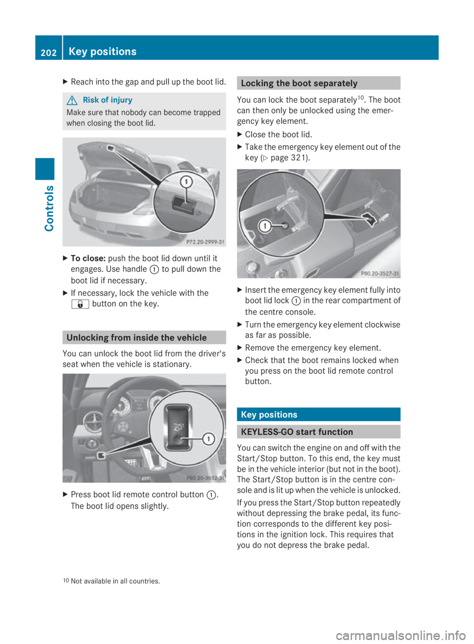
Press boot lid remote control button 0001.
The boot lid opens slightly. Locking the boot separately
You can lock the boot separately 10
.T he boot
can then only be unlocked using the emer-
gency key element.
X Close the boot lid.
X Take the emergency key element out of the
key (Y page 321). X
Insert the emergency key element fully into
boot lid lock 0001in the rear compartment of
the centre console.
X Turn the emergency key element clockwise
as far as possible.
X Remove the emergency key element.
X Check that the boot remains locked when
you press on the boot lid remote control
button. Key positions
KEYLESS-GO startf
unction
You can switch the engine on and off with the
Start/Stop button. To this end, the key must
be in the vehicle interio r(but not in the boot).
The Start/Stop button is in the centre con-
sole and is lit up when the vehicle is unlocked.
If you press the Start/Stop button repeatedly
without depressing the brake pedal, its func-
tion corresponds to the differen tkey posi-
tions in the ignition lock. This requires that
you do not depress the brake pedal.
10 Not available in all countries. 202
Key positionsControls
BA 197 ECE RE 2010/6a; 1; 2, en-GB
sabbaeu
Version: 3.0.3.6 2010-05-07T14:19:43+02:00 - Seite 202
Page 229 of 361
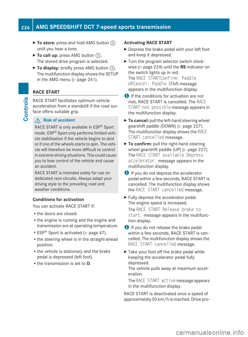
X
To store: press and hold AMG button 0001
until you hea ratone.
X To call up: press AMG button 0001.
The stored drive progra misselected.
X To display: briefly press AMG button 0001.
The multifunction display shows the SETUP
in the AMG menu (Y page 241).
RACE START RACE START facilitates optimum vehicle
acceleration from a standstill if the road sur-
face offers suitable grip. G
Risk of accident
RACE START is only available in ESP ®
Sport
mode. ESP ®
Sport only performs limited vehi-
cle stabilisation if the vehicle begins to skid
or if one of the wheels starts to spin. The vehi-
cle will therefore be more difficult to control
in extreme driving situations. This could cause
you to lose control of the vehicle and cause
an accident.
RACE START is intended solely for use on
dedicated race circuits. Always adapt your
driving style to the prevailing road and
weather conditions.
Conditions for activation
You can activate RACE START if:
R the doors are closed.
R the engine is running and the engine and
transmission are at operating temperature.
R ESP ®
Sport is activated (Y page 47).
R the steering wheel is in the straight-ahead
position.
R the vehicle is stationary and the brake
pedal is depressed (left foot).
R the transmission is set to D.Activating RACE START
X
Depress the brake pedal with your left foot
and keep it depressed.
X Turn the program selector switch clock-
wise (Y page 224)u ntil theRSindicator on
the switch lights up in red.
The RACE STARTConfirm: Paddle
UPCancel: Paddle DOWN message
appears in the multifunctio ndisplay.
i If the conditions for activation are not
met, RACE START is cancelled. The RACE
START not possible message appears in
the multifunction display.
X To cancel: pull the left-hand steering wheel
gearshift paddle (DOWN) (Y page 227).
The multifunction display shows the RACE
START cancelled message.
X To confirm: pull the right-hand steering
wheel gearshift paddle (UP) (Y page 227).
The RACE START available Depress
accelerator. message appears in the
multifunction display.
i If you do not depress the accelerator
pedal within a few seconds ,RACE START is
cancelled. The multifunctio ndisplay shows
the RACE START cancelled message.
X Fully depress the accelerator pedal.
The engine speed is increased.
The RACE START Release brake to
start. message appears in the multifunc-
tion display.
i If you do not release the brake pedal
within a few seconds, RACE START is can-
celled. The multifunction display shows the
RACE START cancelled message.
X Take your foot off the brake pedal while
keeping the accelerator pedal fully
depressed.
The vehicle pulls away at maximum accel-
eration.
The RACE START active message appears
in the multifunction display.
RACE START is deactivated once a speed of
approximately 50 km/h is reached. Drive pro- 226
AMG SPEEDSHIFT DCT 7-speed sports transmissionControls
BA 197 ECE RE 2010/6a; 1; 2, en-GB
sabbaeu
Version: 3.0.3.6 2010-05-07T14:19:43+02:00 - Seite226
Page 257 of 361
Setting the temperature
Different temperatures can be set for the
driver's and front-passenger sides.
X Select key position 2with the Start/Stop
button.
X To increase/reduce: turn controls0001and
000B clockwise or anti-clockwise
(Y page 252). Only change the temperature
settingi n small increments. Start at 22 †. Adjusting the air vents
G
Risk of injury
Very hot or very cold ai rcan flow from the air
vents .This could cause burns or frostbite to
bare skin in the immediate vicinity of the
vents. Keep bare skin away from these air
outlets. If necessary, direct the airflow away
to a different area of the vehicle interior.
In order to ensure the direct flow of fresh air
through the air vents into the vehicle interior,
please observe the following notes:
R keep the air inlet on the right-hand side of
the bonnet free of blockages, such as ice,
snow or leaves.
R never cover the ventsora ir inlet and outlet
grilles in the vehicle interior
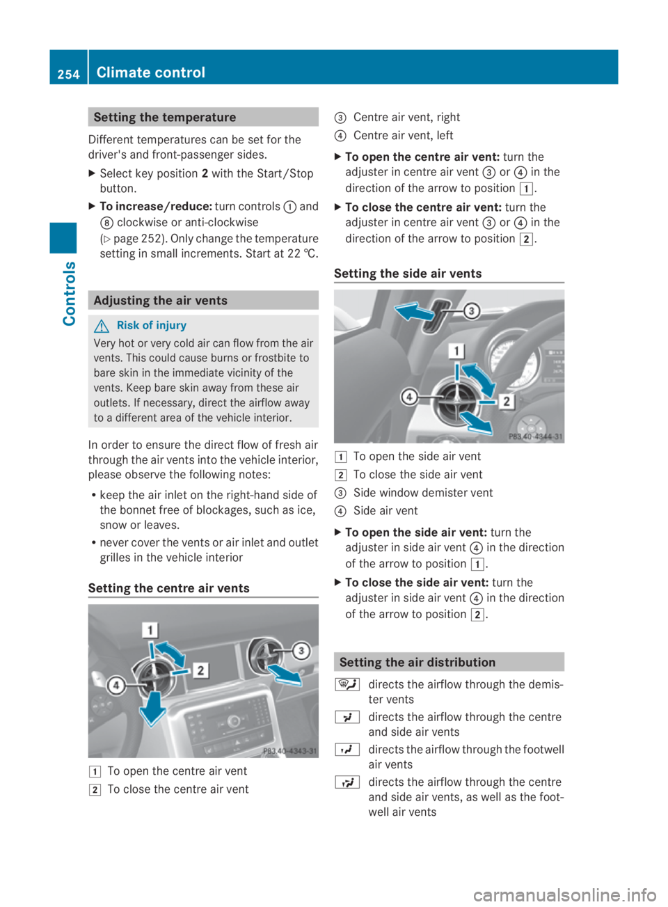
Setting the centre air vents 0003
To open the centre air vent
0004 To close the centre air vent 0015
Centre air vent, right
0014 Centre air vent, left
X To open the centre air vent: turn the
adjuster in centre air vent 0015or0014 in the
direction of the arrow to position 0003.
X To close the centre air vent: turn the
adjuster in centre air vent 0015or0014 in the
direction of the arrow to position 0004.
Setting the side air vents 0003
To open the side air vent
0004 To close the side air vent
0015 Side window demister vent
0014 Side air vent
X To open the side air vent: turn the
adjuster in side air vent 0014in the direction
of the arrow to position 0003.
X To close the side air vent: turn the
adjuster in side air vent 0014in the direction
of the arrow to position 0004. Setting the air distribution
0006 directs the airflow through the demis-
ter vents
0017 directs the airflow through the centre
and side air vents
0016 directs the airflow through the footwell
air vents
0008 directs the airflow through the centre
and side air vents, as well as the foot-
well air vents 254
Climate controlControls
BA 197 ECE RE 2010/6a; 1; 2, en-GB
sabbaeu
Version: 3.0.3.6 2010-05-07T14:19:43+02:00 - Seite254