air condition MERCEDES-BENZ SPRINTER 2006 Service Manual
[x] Cancel search | Manufacturer: MERCEDES-BENZ, Model Year: 2006, Model line: SPRINTER, Model: MERCEDES-BENZ SPRINTER 2006Pages: 2305, PDF Size: 48.12 MB
Page 344 of 2305
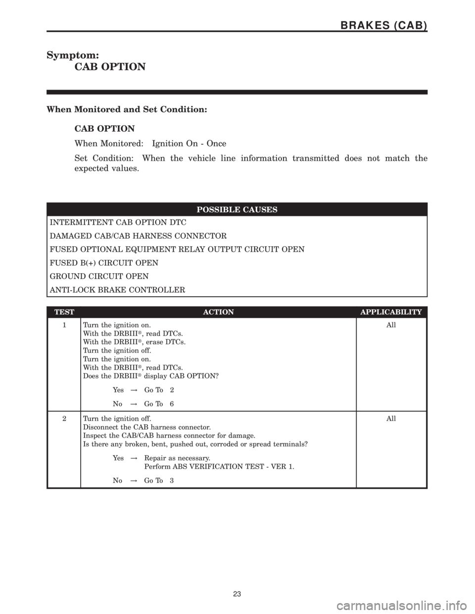
Symptom:
CAB OPTION
When Monitored and Set Condition:
CAB OPTION
When Monitored: Ignition On - Once
Set Condition: When the vehicle line information transmitted does not match the
expected values.
POSSIBLE CAUSES
INTERMITTENT CAB OPTION DTC
DAMAGED CAB/CAB HARNESS CONNECTOR
FUSED OPTIONAL EQUIPMENT RELAY OUTPUT CIRCUIT OPEN
FUSED B(+) CIRCUIT OPEN
GROUND CIRCUIT OPEN
ANTI-LOCK BRAKE CONTROLLER
TEST ACTION APPLICABILITY
1 Turn the ignition on.
With the DRBIIIt, read DTCs.
With the DRBIIIt, erase DTCs.
Turn the ignition off.
Turn the ignition on.
With the DRBIIIt, read DTCs.
Does the DRBIIItdisplay CAB OPTION?All
Ye s!Go To 2
No!Go To 6
2 Turn the ignition off.
Disconnect the CAB harness connector.
Inspect the CAB/CAB harness connector for damage.
Is there any broken, bent, pushed out, corroded or spread terminals?All
Ye s!Repair as necessary.
Perform ABS VERIFICATION TEST - VER 1.
No!Go To 3
23
BRAKES (CAB)
Page 352 of 2305

TEST ACTION APPLICABILITY
7 The condition that set this DTC is not present at this time.
Monitor the DRBIIItwhile wiggle testing the related harness and connectors. Look
for any related parameters to change or for the DTC to reset.
Inspect the related harness and connectors.
Look for any chafed, pierced, pinched, or partially broken wires.
Look for broken, bent, pushed out, or corroded terminals.
Were any problems found?All
Ye s!Repair as necessary.
No!Test Complete.
31
BRAKES (CAB)
DRIVE TEST ERROR ÐContinued
Page 354 of 2305
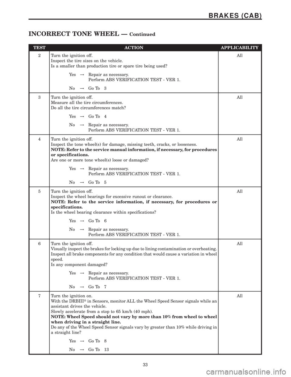
TEST ACTION APPLICABILITY
2 Turn the ignition off.
Inspect the tire sizes on the vehicle.
Is a smaller than production tire or spare tire being used?All
Ye s!Repair as necessary.
Perform ABS VERIFICATION TEST - VER 1.
No!Go To 3
3 Turn the ignition off.
Measure all the tire circumferences.
Do all the tire circumferences match?All
Ye s!Go To 4
No!Repair as necessary.
Perform ABS VERIFICATION TEST - VER 1.
4 Turn the ignition off.
Inspect the tone wheel(s) for damage, missing teeth, cracks, or looseness.
NOTE: Refer to the service manual information, if necessary, for procedures
or specifications.
Are one or more tone wheel(s) loose or damaged?All
Ye s!Repair as necessary.
Perform ABS VERIFICATION TEST - VER 1.
No!Go To 5
5 Turn the ignition off.
Inspect the wheel bearings for excessive runout or clearance.
NOTE: Refer to the service information, if necessary, for procedures or
specifications.
Is the wheel bearing clearance within specifications?All
Ye s!Go To 6
No!Repair as necessary.
Perform ABS VERIFICATION TEST - VER 1.
6 Turn the ignition off.
Visually inspect the brakes for locking up due to lining contamination or overheating.
Inspect all brake components for any condition that would cause a variation in wheel
speed.
Is any component damaged?All
Ye s!Repair as necessary.
Perform ABS VERIFICATION TEST - VER 1.
No!Go To 7
7 Turn the ignition on.
With the DRBIIItin Sensors, monitor ALL the Wheel Speed Sensor signals while an
assistant drives the vehicle.
Slowly accelerate from a stop to 65 km/h (40 mph).
NOTE: Wheel Speed should not vary by more than 10% from wheel to wheel
when driving in a straight line.
Do any of the Wheel Speed Sensor signals vary by greater than 10% while driving in
a straight line?All
Ye s!Go To 8
No!Go To 13
33
BRAKES (CAB)
INCORRECT TONE WHEEL ÐContinued
Page 356 of 2305
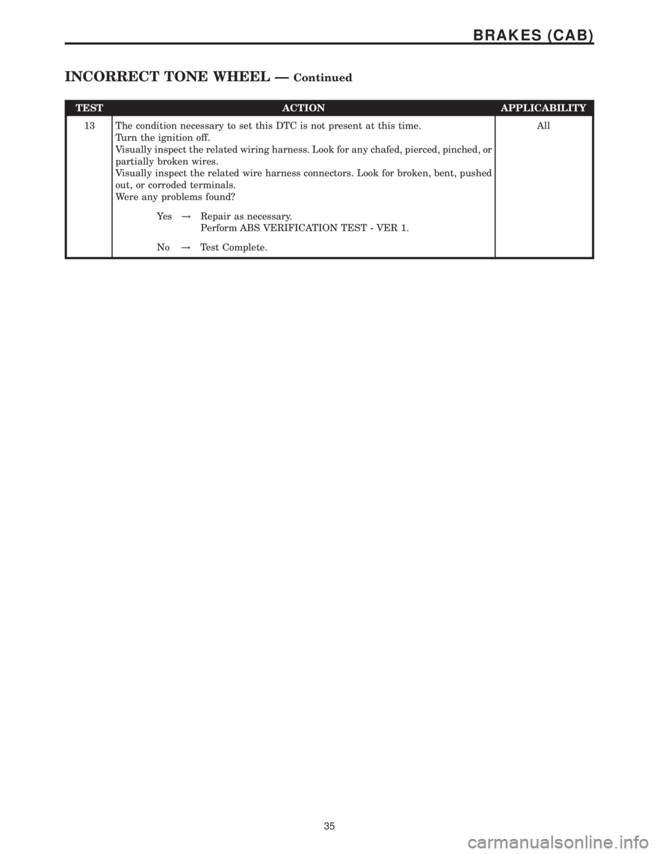
TEST ACTION APPLICABILITY
13 The condition necessary to set this DTC is not present at this time.
Turn the ignition off.
Visually inspect the related wiring harness. Look for any chafed, pierced, pinched, or
partially broken wires.
Visually inspect the related wire harness connectors. Look for broken, bent, pushed
out, or corroded terminals.
Were any problems found?All
Ye s!Repair as necessary.
Perform ABS VERIFICATION TEST - VER 1.
No!Test Complete.
35
BRAKES (CAB)
INCORRECT TONE WHEEL ÐContinued
Page 359 of 2305

TEST ACTION APPLICABILITY
7 The condition that set this DTC is not present at this time.
Monitor the DRBIIItwhile wiggle testing the related harness and connectors. Look
for any related parameters to change or for the DTC to reset.
Inspect the related harness and connectors.
Look for any chafed, pierced, pinched, or partially broken wires.
Look for broken, bent, pushed out, or corroded terminals.
Were any problems found?All
Ye s!Repair as necessary.
No!Test Complete.
38
BRAKES (CAB)
LATERAL ACCELERATION SENSOR CIRCUIT ÐContinued
Page 360 of 2305
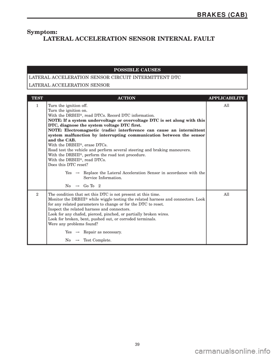
Symptom:
LATERAL ACCELERATION SENSOR INTERNAL FAULT
POSSIBLE CAUSES
LATERAL ACCELERATION SENSOR CIRCUIT INTERMITTENT DTC
LATERAL ACCELERATION SENSOR
TEST ACTION APPLICABILITY
1 Turn the ignition off.
Turn the ignition on.
With the DRBIIIt, read DTCs. Record DTC information.
NOTE: If a system undervoltage or overvoltage DTC is set along with this
DTC, diagnose the system voltage DTC first.
NOTE: Electromagnetic (radio) interference can cause an intermittent
system malfunction by interrupting communication between the sensor
and the CAB.
With the DRBIIIt, erase DTCs.
Road test the vehicle and perform several steering and braking maneuvers.
With the DRBIIIt, perform the road test procedure.
With the DRBIIIt, read DTCs.
Does this DTC reset?All
Ye s!Replace the Lateral Acceleration Sensor in accordance with the
Service Information.
No!Go To 2
2 The condition that set this DTC is not present at this time.
Monitor the DRBIIItwhile wiggle testing the related harness and connectors. Look
for any related parameters to change or for the DTC to reset.
Inspect the related harness and connectors.
Look for any chafed, pierced, pinched, or partially broken wires.
Look for broken, bent, pushed out, or corroded terminals.
Were any problems found?All
Ye s!Repair as necessary.
No!Test Complete.
39
BRAKES (CAB)
Page 367 of 2305
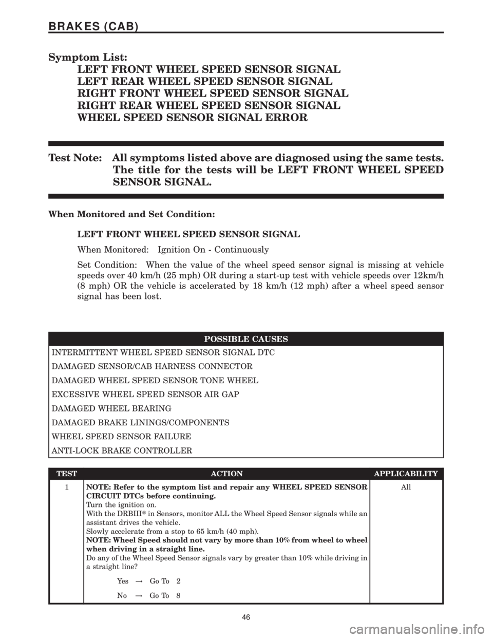
Symptom List:
LEFT FRONT WHEEL SPEED SENSOR SIGNAL
LEFT REAR WHEEL SPEED SENSOR SIGNAL
RIGHT FRONT WHEEL SPEED SENSOR SIGNAL
RIGHT REAR WHEEL SPEED SENSOR SIGNAL
WHEEL SPEED SENSOR SIGNAL ERROR
Test Note: All symptoms listed above are diagnosed using the same tests.
The title for the tests will be LEFT FRONT WHEEL SPEED
SENSOR SIGNAL.
When Monitored and Set Condition:
LEFT FRONT WHEEL SPEED SENSOR SIGNAL
When Monitored: Ignition On - Continuously
Set Condition: When the value of the wheel speed sensor signal is missing at vehicle
speeds over 40 km/h (25 mph) OR during a start-up test with vehicle speeds over 12km/h
(8 mph) OR the vehicle is accelerated by 18 km/h (12 mph) after a wheel speed sensor
signal has been lost.
POSSIBLE CAUSES
INTERMITTENT WHEEL SPEED SENSOR SIGNAL DTC
DAMAGED SENSOR/CAB HARNESS CONNECTOR
DAMAGED WHEEL SPEED SENSOR TONE WHEEL
EXCESSIVE WHEEL SPEED SENSOR AIR GAP
DAMAGED WHEEL BEARING
DAMAGED BRAKE LININGS/COMPONENTS
WHEEL SPEED SENSOR FAILURE
ANTI-LOCK BRAKE CONTROLLER
TEST ACTION APPLICABILITY
1NOTE: Refer to the symptom list and repair any WHEEL SPEED SENSOR
CIRCUIT DTCs before continuing.
Turn the ignition on.
With the DRBIIItin Sensors, monitor ALL the Wheel Speed Sensor signals while an
assistant drives the vehicle.
Slowly accelerate from a stop to 65 km/h (40 mph).
NOTE: Wheel Speed should not vary by more than 10% from wheel to wheel
when driving in a straight line.
Do any of the Wheel Speed Sensor signals vary by greater than 10% while driving in
a straight line?All
Ye s!Go To 2
No!Go To 8
46
BRAKES (CAB)
Page 369 of 2305
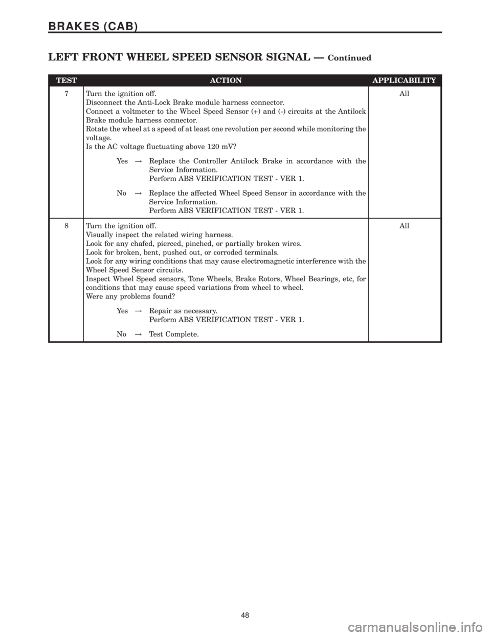
TEST ACTION APPLICABILITY
7 Turn the ignition off.
Disconnect the Anti-Lock Brake module harness connector.
Connect a voltmeter to the Wheel Speed Sensor (+) and (-) circuits at the Antilock
Brake module harness connector.
Rotate the wheel at a speed of at least one revolution per second while monitoring the
voltage.
Is the AC voltage fluctuating above 120 mV?All
Ye s!Replace the Controller Antilock Brake in accordance with the
Service Information.
Perform ABS VERIFICATION TEST - VER 1.
No!Replace the affected Wheel Speed Sensor in accordance with the
Service Information.
Perform ABS VERIFICATION TEST - VER 1.
8 Turn the ignition off.
Visually inspect the related wiring harness.
Look for any chafed, pierced, pinched, or partially broken wires.
Look for broken, bent, pushed out, or corroded terminals.
Look for any wiring conditions that may cause electromagnetic interference with the
Wheel Speed Sensor circuits.
Inspect Wheel Speed sensors, Tone Wheels, Brake Rotors, Wheel Bearings, etc, for
conditions that may cause speed variations from wheel to wheel.
Were any problems found?All
Ye s!Repair as necessary.
Perform ABS VERIFICATION TEST - VER 1.
No!Test Complete.
48
BRAKES (CAB)
LEFT FRONT WHEEL SPEED SENSOR SIGNAL ÐContinued
Page 374 of 2305
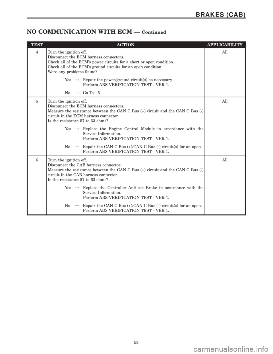
TEST ACTION APPLICABILITY
4 Turn the ignition off.
Disconnect the ECM harness connectors.
Check all of the ECM's power circuits for a short or open condition.
Check all of the ECM's ground circuits for an open condition.
Were any problems found?All
Ye s!Repair the power/ground circuit(s) as necessary.
Perform ABS VERIFICATION TEST - VER 1.
No!Go To 5
5 Turn the ignition off.
Disconnect the ECM harness connectors.
Measure the resistance between the CAN C Bus (+) circuit and the CAN C Bus (-)
circuit in the ECM harness connector.
Is the resistance 57 to 63 ohms?All
Ye s!Replace the Engine Control Module in accordance with the
Service Information.
Perform ABS VERIFICATION TEST - VER 1.
No!Repair the CAN C Bus (+)/CAN C Bus (-) circuit(s) for an open.
Perform ABS VERIFICATION TEST - VER 1.
6 Turn the ignition off.
Disconnect the CAB harness connector.
Measure the resistance between the CAN C Bus (+) circuit and the CAN C Bus (-)
circuit in the CAB harness connector.
Is the resistance 57 to 63 ohms?All
Ye s!Replace the Controller Antilock Brake in accordance with the
Service Information.
Perform ABS VERIFICATION TEST - VER 1.
No!Repair the CAN C Bus (+)/CAN C Bus (-) circuit(s) for an open.
Perform ABS VERIFICATION TEST - VER 1.
53
BRAKES (CAB)
NO COMMUNICATION WITH ECM ÐContinued
Page 376 of 2305
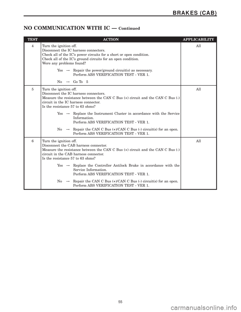
TEST ACTION APPLICABILITY
4 Turn the ignition off.
Disconnect the IC harness connectors.
Check all of the IC's power circuits for a short or open condition.
Check all of the IC's ground circuits for an open condition.
Were any problems found?All
Ye s!Repair the power/ground circuit(s) as necessary.
Perform ABS VERIFICATION TEST - VER 1.
No!Go To 5
5 Turn the ignition off.
Disconnect the IC harness connectors.
Measure the resistance between the CAN C Bus (+) circuit and the CAN C Bus (-)
circuit in the IC harness connector.
Is the resistance 57 to 63 ohms?All
Ye s!Replace the Instrument Cluster in accordance with the Service
Information.
Perform ABS VERIFICATION TEST - VER 1.
No!Repair the CAN C Bus (+)/CAN C Bus (-) circuit(s) for an open.
Perform ABS VERIFICATION TEST - VER 1.
6 Turn the ignition off.
Disconnect the CAB harness connector.
Measure the resistance between the CAN C Bus (+) circuit and the CAN C Bus (-)
circuit in the CAB harness connector.
Is the resistance 57 to 63 ohms?All
Ye s!Replace the Controller Antilock Brake in accordance with the
Service Information.
Perform ABS VERIFICATION TEST - VER 1.
No!Repair the CAN C Bus (+)/CAN C Bus (-) circuit(s) for an open.
Perform ABS VERIFICATION TEST - VER 1.
55
BRAKES (CAB)
NO COMMUNICATION WITH IC ÐContinued