MERCEDES-BENZ SPRINTER 2006 Service Manual
Manufacturer: MERCEDES-BENZ, Model Year: 2006, Model line: SPRINTER, Model: MERCEDES-BENZ SPRINTER 2006Pages: 2305, PDF Size: 48.12 MB
Page 1951 of 2305
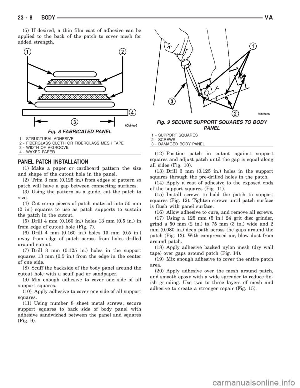
(5) If desired, a thin film coat of adhesive can be
applied to the back of the patch to cover mesh for
added strength.
PANEL PATCH INSTALLATION
(1) Make a paper or cardboard pattern the size
and shape of the cutout hole in the panel.
(2) Trim 3 mm (0.125 in.) from edges of pattern so
patch will have a gap between connecting surfaces.
(3) Using the pattern as a guide, cut the patch to
size.
(4) Cut scrap pieces of patch material into 50 mm
(2 in.) squares to use as patch supports to sustain
the patch in the cutout.
(5) Drill 4 mm (0.160 in.) holes 13 mm (0.5 in.) in
from edge of cutout hole (Fig. 7).
(6) Drill 4 mm (0.160 in.) holes 13 mm (0.5 in.)
away from edge of patch across from holes drilled
around cutout.
(7) Drill 3 mm (0.125 in.) holes in the support
squares 13 mm (0.5 in.) from the edge in the center
of one side.
(8) Scuff the backside of the body panel around the
cutout hole with a scuff pad or sandpaper.
(9) Mix enough adhesive to cover one side of all
support squares.
(10) Apply adhesive to cover one side of all support
squares.
(11) Using number 8 sheet metal screws, secure
support squares to back side of body panel with
adhesive sandwiched between the panel and squares
(Fig. 9).(12) Position patch in cutout against support
squares and adjust patch until the gap is equal along
all sides (Fig. 10).
(13) Drill 3 mm (0.125 in.) holes in the support
squares through the pre-drilled holes in the patch.
(14) Apply a coat of adhesive to the exposed ends
of the support squares (Fig. 11).
(15) Install screws to hold the patch to support
squares (Fig. 12). Tighten screws until patch surface
is flush with panel surface.
(16) Allow adhesive to cure, and remove all screws.
(17) Using a 125 mm (5 in.) 24 grit disc grinder,
grind a 50 mm (2 in.) to 75 mm (3 in.) wide and 2
mm (0.080 in.) deep path across the gaps around the
patch (Fig. 13). With compressed air, blow dust from
around patch.
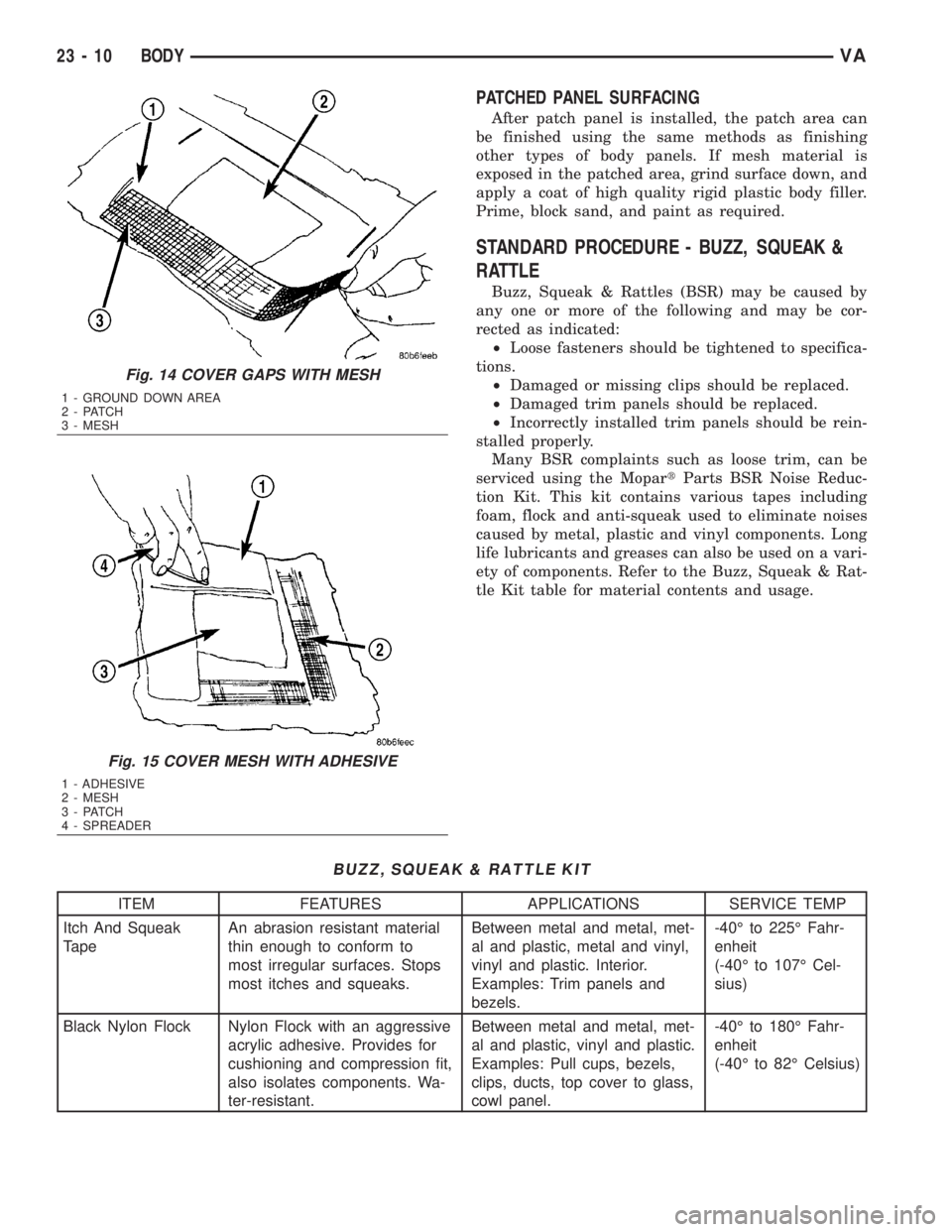
(18) Apply adhesive backed nylon mesh (dry wall
tape) over gaps around patch (Fig. 14).
(19) Mix enough adhesive to cover the entire patch
area.
(20) Apply adhesive over the mesh around patch,
and smooth epoxy with a wide spreader to reduce fin-
ish grinding. Use two to three layers of mesh and
adhesive to create a stronger repair (Fig. 15).
Fig. 8 FABRICATED PANEL
1 - STRUCTURAL ADHESIVE
2 - FIBERGLASS CLOTH OR FIBERGLASS MESH TAPE
3 - WIDTH OF V-GROOVE
4 - WAXED PAPER
Fig. 9 SECURE SUPPORT SQUARES TO BODY
PANEL
1 - SUPPORT SQUARES
2 - SCREWS
3 - DAMAGED BODY PANEL
23 - 8 BODYVA
Page 1952 of 2305
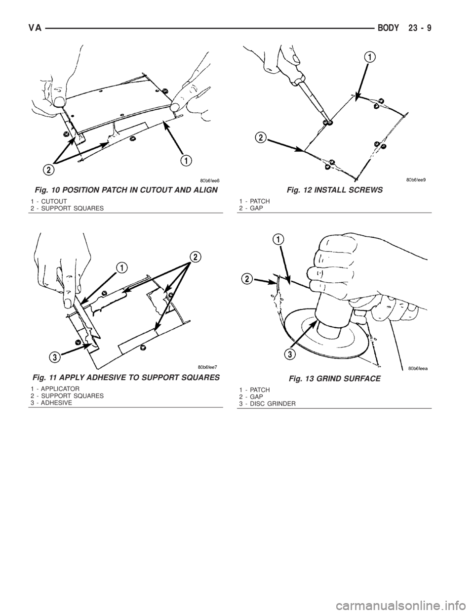
Fig. 10 POSITION PATCH IN CUTOUT AND ALIGN
1 - CUTOUT
2 - SUPPORT SQUARES
Fig. 11 APPLY ADHESIVE TO SUPPORT SQUARES
1 - APPLICATOR
2 - SUPPORT SQUARES
3 - ADHESIVE
Fig. 12 INSTALL SCREWS
1 - PATCH
2 - GAP
Fig. 13 GRIND SURFACE
1 - PATCH
2 - GAP
3 - DISC GRINDER
VABODY 23 - 9
Page 1953 of 2305
PATCHED PANEL SURFACING
After patch panel is installed, the patch area can
be finished using the same methods as finishing
other types of body panels. If mesh material is
exposed in the patched area, grind surface down, and
apply a coat of high quality rigid plastic body filler.
Prime, block sand, and paint as required.
STANDARD PROCEDURE - BUZZ, SQUEAK &
RATTLE
Buzz, Squeak & Rattles (BSR) may be caused by
any one or more of the following and may be cor-
rected as indicated:
²Loose fasteners should be tightened to specifica-
tions.
²Damaged or missing clips should be replaced.
²Damaged trim panels should be replaced.
²Incorrectly installed trim panels should be rein-
stalled properly.
Many BSR complaints such as loose trim, can be
serviced using the MopartParts BSR Noise Reduc-
tion Kit. This kit contains various tapes including
foam, flock and anti-squeak used to eliminate noises
caused by metal, plastic and vinyl components. Long
life lubricants and greases can also be used on a vari-
ety of components. Refer to the Buzz, Squeak & Rat-
tle Kit table for material contents and usage.
BUZZ, SQUEAK & RATTLE KIT
ITEM FEATURES APPLICATIONS SERVICE TEMP
Itch And Squeak
TapeAn abrasion resistant material
thin enough to conform to
most irregular surfaces. Stops
most itches and squeaks.Between metal and metal, met-
al and plastic, metal and vinyl,
vinyl and plastic. Interior.
Examples: Trim panels and
bezels.-40É to 225É Fahr-
enheit
(-40É to 107É Cel-
sius)
Black Nylon Flock Nylon Flock with an aggressive
acrylic adhesive. Provides for
cushioning and compression fit,
also isolates components. Wa-
ter-resistant.Between metal and metal, met-
al and plastic, vinyl and plastic.
Examples: Pull cups, bezels,
clips, ducts, top cover to glass,
cowl panel.-40É to 180É Fahr-
enheit
(-40É to 82É Celsius)
Fig. 14 COVER GAPS WITH MESH
1 - GROUND DOWN AREA
2 - PATCH
3 - MESH
Fig. 15 COVER MESH WITH ADHESIVE
1 - ADHESIVE
2 - MESH
3 - PATCH
4 - SPREADER
23 - 10 BODYVA
Page 1954 of 2305
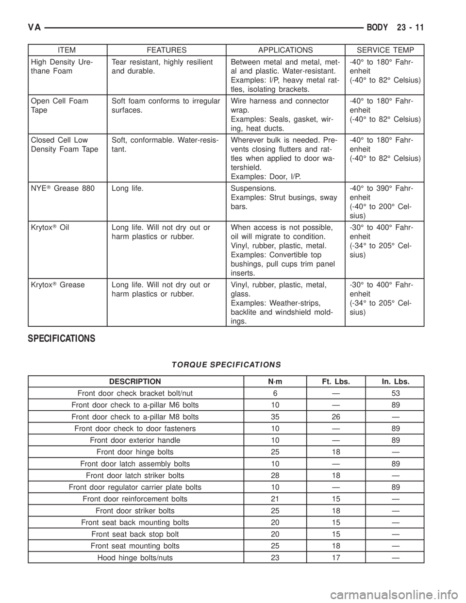
ITEM FEATURES APPLICATIONS SERVICE TEMP
High Density Ure-
thane FoamTear resistant, highly resilient
and durable.Between metal and metal, met-
al and plastic. Water-resistant.
Examples: I/P, heavy metal rat-
tles, isolating brackets.-40É to 180É Fahr-
enheit
(-40É to 82É Celsius)
Open Cell Foam
TapeSoft foam conforms to irregular
surfaces.Wire harness and connector
wrap.
Examples: Seals, gasket, wir-
ing, heat ducts.-40É to 180É Fahr-
enheit
(-40É to 82É Celsius)
Closed Cell Low
Density Foam TapeSoft, conformable. Water-resis-
tant.Wherever bulk is needed. Pre-
vents closing flutters and rat-
tles when applied to door wa-
tershield.
Examples: Door, I/P.-40É to 180É Fahr-
enheit
(-40É to 82É Celsius)
NYETGrease 880 Long life. Suspensions.
Examples: Strut busings, sway
bars.-40É to 390É Fahr-
enheit
(-40É to 200É Cel-
sius)
KrytoxTOil Long life. Will not dry out or
harm plastics or rubber.When access is not possible,
oil will migrate to condition.
Vinyl, rubber, plastic, metal.
Examples: Convertible top
bushings, pull cups trim panel
inserts.-30É to 400É Fahr-
enheit
(-34É to 205É Cel-
sius)
KrytoxTGrease Long life. Will not dry out or
harm plastics or rubber.Vinyl, rubber, plastic, metal,
glass.
Examples: Weather-strips,
backlite and windshield mold-
ings.-30É to 400É Fahr-
enheit
(-34É to 205É Cel-
sius)
SPECIFICATIONS
TORQUE SPECIFICATIONS
DESCRIPTION N´m Ft. Lbs. In. Lbs.
Front door check bracket bolt/nut 6 Ð 53
Front door check to a-pillar M6 bolts 10 Ð 89
Front door check to a-pillar M8 bolts 35 26 Ð
Front door check to door fasteners 10 Ð 89
Front door exterior handle 10 Ð 89
Front door hinge bolts 25 18 Ð
Front door latch assembly bolts 10 Ð 89
Front door latch striker bolts 28 18 Ð
Front door regulator carrier plate bolts 10 Ð 89
Front door reinforcement bolts 21 15 Ð
Front door striker bolts 25 18 Ð
Front seat back mounting bolts 20 15 Ð
Front seat back stop bolt 20 15 Ð
Front seat mounting bolts 25 18 Ð
Hood hinge bolts/nuts 23 17 Ð
VABODY 23 - 11
Page 1955 of 2305
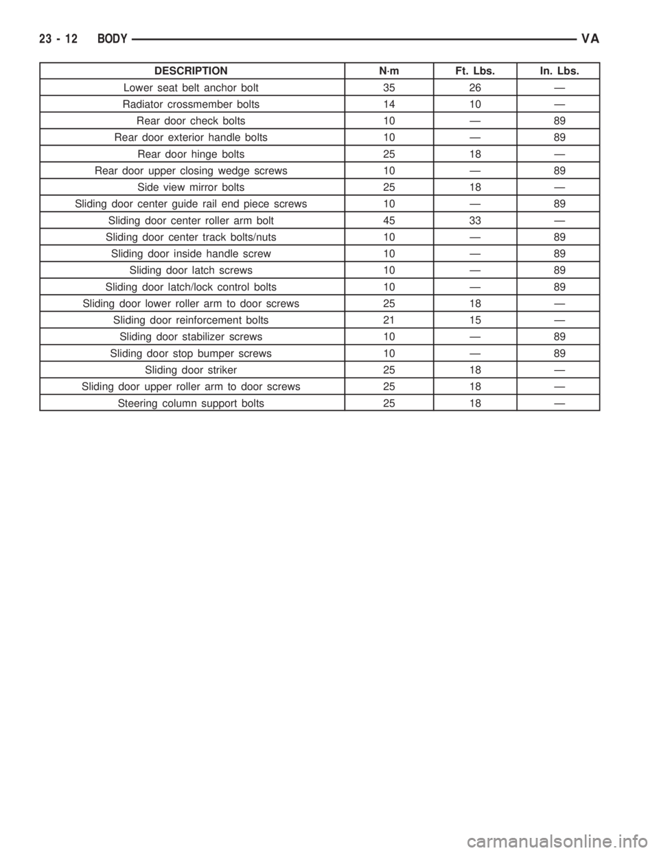
DESCRIPTION N´m Ft. Lbs. In. Lbs.
Lower seat belt anchor bolt 35 26 Ð
Radiator crossmember bolts 14 10 Ð
Rear door check bolts 10 Ð 89
Rear door exterior handle bolts 10 Ð 89
Rear door hinge bolts 25 18 Ð
Rear door upper closing wedge screws 10 Ð 89
Side view mirror bolts 25 18 Ð
Sliding door center guide rail end piece screws 10 Ð 89
Sliding door center roller arm bolt 45 33 Ð
Sliding door center track bolts/nuts 10 Ð 89
Sliding door inside handle screw 10 Ð 89
Sliding door latch screws 10 Ð 89
Sliding door latch/lock control bolts 10 Ð 89
Sliding door lower roller arm to door screws 25 18 Ð
Sliding door reinforcement bolts 21 15 Ð
Sliding door stabilizer screws 10 Ð 89
Sliding door stop bumper screws 10 Ð 89
Sliding door striker 25 18 Ð
Sliding door upper roller arm to door screws 25 18 Ð
Steering column support bolts 25 18 Ð
23 - 12 BODYVA
Page 1956 of 2305
DOOR - FRONT
TABLE OF CONTENTS
page page
CHECK
REMOVAL.............................13
INSTALLATION.........................13
DOOR
REMOVAL.............................14
INSTALLATION.........................14
ADJUSTMENTS
ADJUSTMENT........................15
DOOR GLASS
REMOVAL.............................15
INSTALLATION.........................15
EXTERIOR HANDLE
REMOVAL.............................16
INSTALLATION.........................16
HINGE
REMOVAL.............................17
INSTALLATION.........................17
LATCH
REMOVAL.............................18INSTALLATION.........................18
LATCH STRIKER
REMOVAL.............................18
INSTALLATION.........................18
LOCK CYLINDER
REMOVAL.............................18
INSTALLATION.........................18
TRIM PANEL
REMOVAL.............................18
INSTALLATION.........................20
WINDOW REGULATOR - POWER
REMOVAL.............................20
INSTALLATION.........................21
WINDOW REGULATOR - MANUAL
REMOVAL.............................21
INSTALLATION.........................22
CHECK
REMOVAL
(1) Disconnect and isolate the battery negative
cable.
(2) Remove trim panel. (Refer to 23 - BODY/DOOR
- FRONT/TRIM PANEL - REMOVAL)
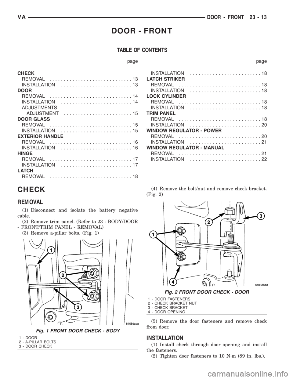
(3) Remove a-pillar bolts. (Fig. 1)(4) Remove the bolt/nut and remove check bracket.
(Fig. 2)
(5) Remove the door fasteners and remove check
from door.
INSTALLATION
(1) Install check through door opening and install
the fasteners.
(2) Tighten door fasteners to 10 N´m (89 in. lbs.).
Fig. 1 FRONT DOOR CHECK - BODY
1 - DOOR
2 - A-PILLAR BOLTS
3 - DOOR CHECK
Fig. 2 FRONT DOOR CHECK - DOOR
1 - DOOR FASTENERS
2 - CHECK BRACKET NUT
3 - CHECK BRACKET
4 - DOOR OPENING
VADOOR - FRONT 23 - 13
Page 1957 of 2305
(3) Install bracket onto check and install bracket
bolt/nut.
(4) Tighten bracket bolt/nut to 6 N´m (53 in. lbs.).
(5) Install check bracket onto a-pillar.
(6) Apply Loctitet243 sealant check strap bolts
and install bolts.
(7) Tighten the M8 bolts to 35 N´m (26 ft. lbs.) or
tighten the M6 bolts to 10 N´m (89 in. lbs.).
(8) Install trim panel. (Refer to 23 - BODY/DOOR -
FRONT/TRIM PANEL - INSTALLATION)
(9) Connect battery negative cable.
DOOR
REMOVAL
(1) Disconnect and isolate battery negative cable.
(2) Remove mirror. (Refer to 23 - BODY/EXTERI-
OR/SIDE VIEW MIRROR - REMOVAL)
(3) Position aside the wiring boot and disconnect
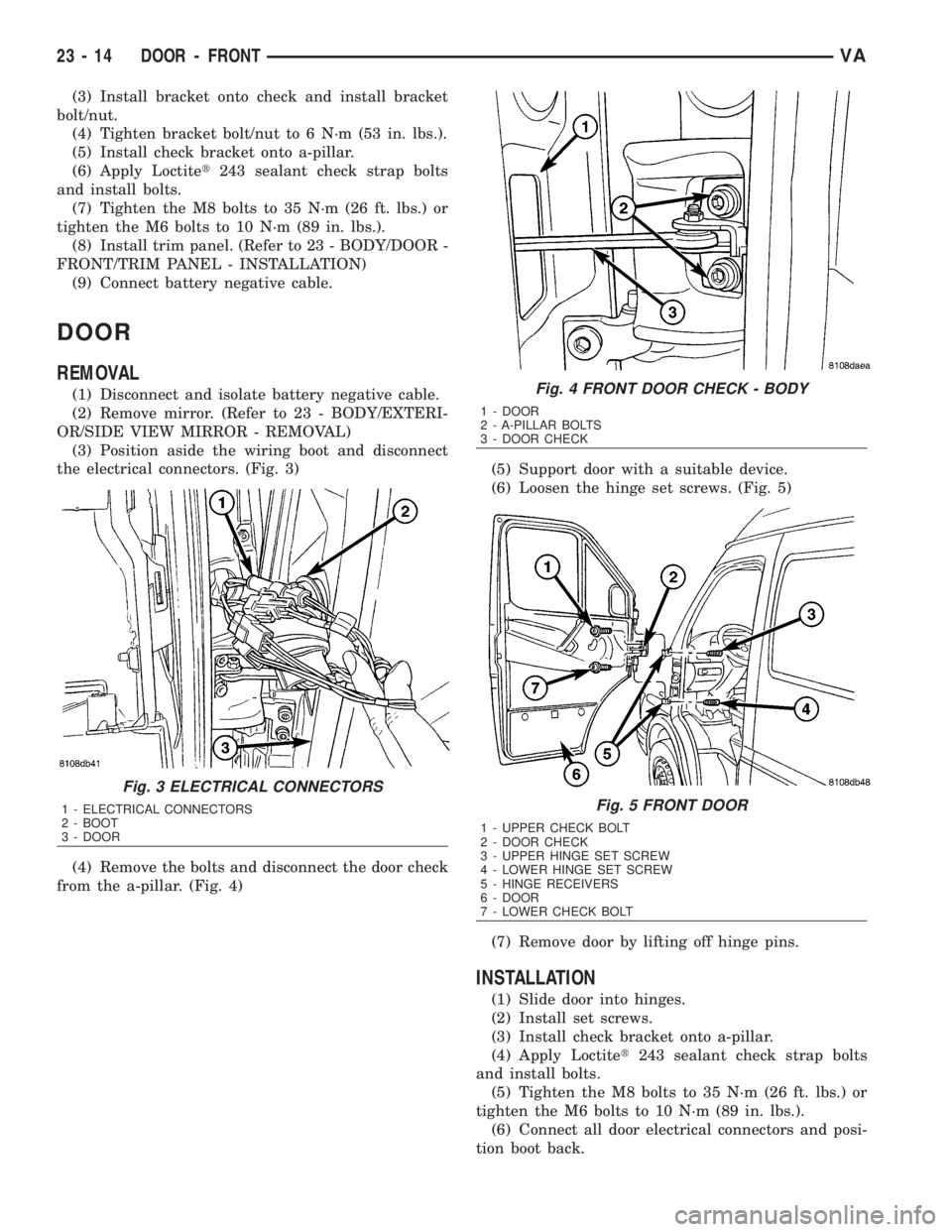
the electrical connectors. (Fig. 3)
(4) Remove the bolts and disconnect the door check
from the a-pillar. (Fig. 4)(5) Support door with a suitable device.
(6) Loosen the hinge set screws. (Fig. 5)
(7) Remove door by lifting off hinge pins.
INSTALLATION
(1) Slide door into hinges.
(2) Install set screws.
(3) Install check bracket onto a-pillar.
(4) Apply Loctitet243 sealant check strap bolts
and install bolts.
(5) Tighten the M8 bolts to 35 N´m (26 ft. lbs.) or
tighten the M6 bolts to 10 N´m (89 in. lbs.).
(6) Connect all door electrical connectors and posi-
tion boot back.
Fig. 3 ELECTRICAL CONNECTORS
1 - ELECTRICAL CONNECTORS
2 - BOOT
3 - DOOR
Fig. 4 FRONT DOOR CHECK - BODY
1 - DOOR
2 - A-PILLAR BOLTS
3 - DOOR CHECK
Fig. 5 FRONT DOOR
1 - UPPER CHECK BOLT
2 - DOOR CHECK
3 - UPPER HINGE SET SCREW
4 - LOWER HINGE SET SCREW
5 - HINGE RECEIVERS
6 - DOOR
7 - LOWER CHECK BOLT
23 - 14 DOOR - FRONTVA
Page 1958 of 2305
(7) Install mirror. (Refer to 23 - BODY/EXTERI-
OR/SIDE VIEW MIRROR - INSTALLATION)
(8) Adjust door if required. (Refer to 23 - BODY/
DOOR - FRONT/DOOR - ADJUSTMENTS)
(9) Connect battery negative cable.
ADJUSTMENTS
ADJUSTMENT
NOTE: Door adjustment measurements should be
taken from stationary or welded body panels like
the roof, rocker or quarter panels.
²During adjustment procedures, it is recom-
mended that all the hinge fasteners be loosened
except for the upper most fasteners. Adjustments
can be made using the upper bolts to hold the door
with final torque of the fasteners occurring after
correct door positioning is achieved.
²A suitable body sealant should be used when
removing or moving the hinges.
(1) Check door alignment. (Refer to 23 - BODY/
BODY STRUCTURE/GAP AND FLUSH - SPECIFI-
CATIONS)
(2) If adjustment is required, remove latch striker.
(Refer to 23 - BODY/DOOR - FRONT/LATCH
STRIKER - REMOVAL)
(3) Remove side view mirror. (Refer to 23 - BODY/
EXTERIOR/SIDE VIEW MIRROR - REMOVAL)
(4) Loosen hinge bolts and adjust door gap and
align ridge pattern as necessary.
(5) Tighten hinge bolts to 25 N´m (18 ft. lbs.).
(6) Install latch striker and adjust flush measure-
ment as necessary. (Refer to 23 - BODY/DOOR -
FRONT/LATCH STRIKER - INSTALLATION)
(7) Install side view mirror. (Refer to 23 - BODY/
EXTERIOR/SIDE VIEW MIRROR - INSTALLA-
TION)
DOOR GLASS
REMOVAL
(1) Remove the regulator. (Refer to 23 - BODY/
DOOR - FRONT/WINDOW REGULATOR - POWER
or MANUAL - REMOVAL)
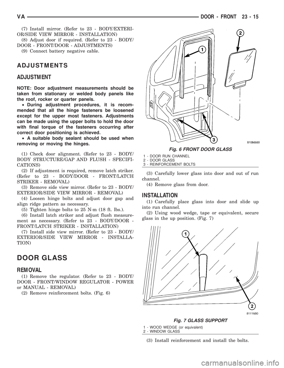
(2) Remove reinforcement bolts. (Fig. 6)(3) Carefully lower glass into door and out of run
channel.
(4) Remove glass from door.
INSTALLATION
(1) Carefully place glass into door and slide up
into run channel.
(2) Using wood wedge, tape or equivalent, secure
glass in the up position. (Fig. 7)
(3) Install reinforcement and install the bolts.
Fig. 6 FRONT DOOR GLASS
1 - DOOR RUN CHANNEL
2 - DOOR GLASS
3 - REINFORCEMENT BOLTS
Fig. 7 GLASS SUPPORT
1 - WOOD WEDGE (or equivalent)
2 - WINDOW GLASS
VADOOR - FRONT 23 - 15
Page 1959 of 2305
(4) Tighten the reinforcement bolts to 21 N´m (18
ft. lbs.).
(5) Install the regulator. (Refer to 23 - BODY/
DOOR - FRONT/WINDOW REGULATOR - POWER
or MANUAL - INSTALLATION)
EXTERIOR HANDLE
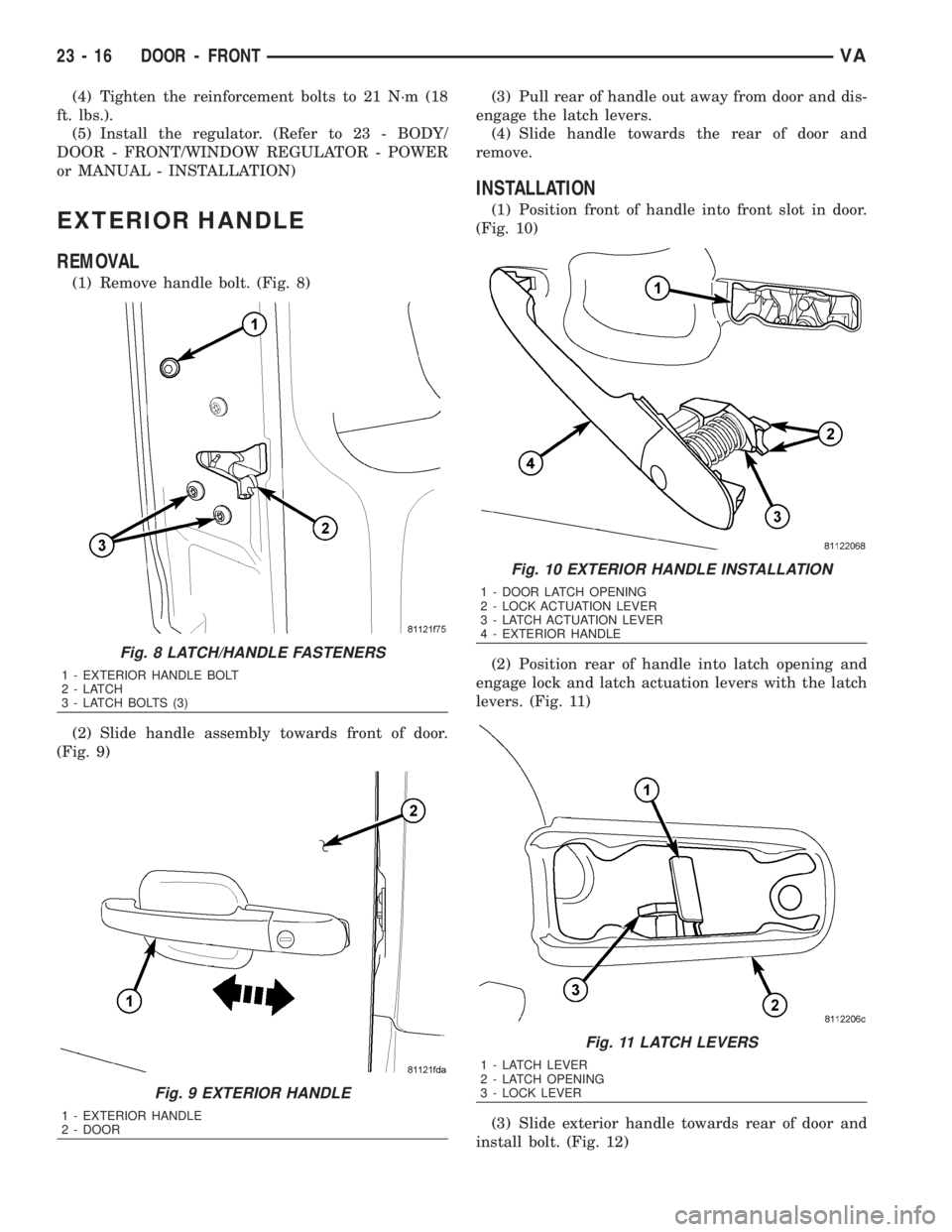
REMOVAL
(1) Remove handle bolt. (Fig. 8)
(2) Slide handle assembly towards front of door.
(Fig. 9)(3) Pull rear of handle out away from door and dis-
engage the latch levers.
(4) Slide handle towards the rear of door and
remove.
INSTALLATION
(1) Position front of handle into front slot in door.
(Fig. 10)
(2) Position rear of handle into latch opening and
engage lock and latch actuation levers with the latch
levers. (Fig. 11)
(3) Slide exterior handle towards rear of door and
install bolt. (Fig. 12)
Fig. 8 LATCH/HANDLE FASTENERS
1 - EXTERIOR HANDLE BOLT
2-LATCH
3 - LATCH BOLTS (3)
Fig. 9 EXTERIOR HANDLE
1 - EXTERIOR HANDLE
2 - DOOR
Fig. 10 EXTERIOR HANDLE INSTALLATION
1 - DOOR LATCH OPENING
2 - LOCK ACTUATION LEVER
3 - LATCH ACTUATION LEVER
4 - EXTERIOR HANDLE
Fig. 11 LATCH LEVERS
1 - LATCH LEVER
2 - LATCH OPENING
3 - LOCK LEVER
23 - 16 DOOR - FRONTVA
Page 1960 of 2305
(4) Tighten bolt to 10 N´m (89 in. lbs.).
HINGE
REMOVAL
NOTE: It is not necessary to remove the door to
replace the hinges if they are replaced one at a
time.
(1) Using a grease pencil or equivalent, mark the
position of the hinge on the door.
(2) Remove side view mirror. (Refer to 23 - BODY/
EXTERIOR/SIDE VIEW MIRROR - REMOVAL)
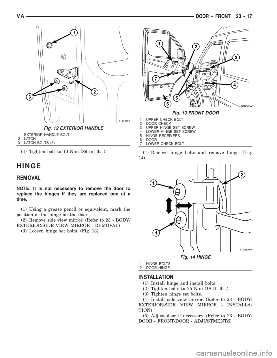
(3) Loosen hinge set bolts. (Fig. 13)(4) Remove hinge bolts and remove hinge. (Fig.
14)
INSTALLATION
(1) Install hinge and install bolts.
(2) Tighten bolts to 25 N´m (18 ft. lbs.).
(3) Tighten hinge set bolts.
(4) Install side view mirror. (Refer to 23 - BODY/
EXTERIOR/SIDE VIEW MIRROR - INSTALLA-
TION)
(5) Adjust door if necessary. (Refer to 23 - BODY/
DOOR - FRONT/DOOR - ADJUSTMENTS)
Fig. 12 EXTERIOR HANDLE
1 - EXTERIOR HANDLE BOLT
2-LATCH
3 - LATCH BOLTS (3)
Fig. 13 FRONT DOOR
1 - UPPER CHECK BOLT
2 - DOOR CHECK
3 - UPPER HINGE SET SCREW
4 - LOWER HINGE SET SCREW
5 - HINGE RECEIVERS
6 - DOOR
7 - LOWER CHECK BOLT
Fig. 14 HINGE
1 - HINGE BOLTS
2 - DOOR HINGE
VADOOR - FRONT 23 - 17