power steering MERCEDES-BENZ SPRINTER 2006 Service Manual
[x] Cancel search | Manufacturer: MERCEDES-BENZ, Model Year: 2006, Model line: SPRINTER, Model: MERCEDES-BENZ SPRINTER 2006Pages: 2305, PDF Size: 48.12 MB
Page 15 of 2305
secured to the floor under the Driver seat and
receives power from the Fuse Block No. 1. When-
ever the ignition key is turned to the run or start
position, the ACM performs a system test. The ACM
cannot be repaired or adjusted.
The microprocessor in the ACM monitors the
internal and external airbag system electrical cir-
cuits to determine the system readiness. When a
monitored system is determine to be out of range,
the ACM will set both active and stored diagnostic
trouble codes (DTC). The ACM also contains an
energy-storage capacitor. This capacitor stores
enough electrical energy to deploy the front airbag
components for two seconds following a battery
disconnect or failure during an impact.
The Accelerometer in the ACM is used to sense
the rate of vehicle deceleration, provide verification
of the direction and severity of an impact. When the
preprogrammed conditions are met, the ACM sends
an electrical signal to deploy the appropriate front
airbag system components and a deployment noti-
fication.
To provide an accident response notification, the
ACM is hardwired to the Central Timer module
(CTM) and Engine Control Module (ECM). When a
deployment occurs the ACM provides a 50ms 10.0
volt pulse to the CTM and ECM. When the Accident
Report notification signal is received the CTM un-
locks the door locks and the ECM stalls the engine.
The Accident signal will set a DTC in the CTM and
the door locks will not work until the DTC has been
erased. The ECM will set a DTC if the Accident
Report circuit is shorted to battery voltage. The
ACM saves the deployment record and after three
deployments the ACM must be replaced. The
DRBIIItcan be used to test the Accident Report
Notification feature: select the SYSTEM TEST from
the ACM main menu. Then select the Analog Crash
Output System Test.
The ACM is hardwired to the Instrument Cluster
(MIC) to control Warning Indicator (SRS indicator).
When DTCs becomes activate, the ACM illuminates
the Warning Indicator by pulling the indicator
circuit low. The SRS indicator is the only point at
which the customer can observe symptoms of a
system malfunction.
As part of the system test the ACM illuminates
the Warning Indicator on for 4.0 second bulb test.
After the lamp check, if the indicator turns off, it
means that the ACM has checked the system and
found it to be free of discernible malfunctions.
NON-CRITICAL DTCs
If the lamp comes on and stays on for a period
longer than 4.0 seconds (about 10.0 seconds) is
usually a stored DTC (intermittent problem) in the
system.
CRITICAL DTCs
DTCs that could lead to a condition where the
safety devises may not deploy or incorrectly deploy.
In the event of such a DTC, the safety of the vehicle
occupants can no longer be guaranteed. If the lamp
remains on, there could be an active DTC in the
system. Some DTCs, Internal Module and squib
DTCs, will keep the indicator illuminated even if
the codes are no longer active.
ACM NOT CONFIGURED FOR PASSENGER
AIRBAG AND TENSIONER
If after replacing the ACM the Airbag Warning
Indicator flashes continuously the ACM must be
configured for the Passenger Airbag and Tensioner.
Select Miscellaneous from the ACM main menu and
configure the Passenger Airbag Tensioner squibs.
WARNING:THE AIRBAG SYSTEM IS A
SENSITIVE, COMPLEX ELECTROMECHANICAL
UNIT. BEFORE ATTEMPTING TO DIAGNOSE OR
SERVICE ANY AIRBAG SYSTEM OR RELATED
STEERING WHEEL, STEERING COLUMN, OR
INSTRUMENT PANEL COMPONENTS YOU MUST
FIRST DISCONNECT AND ISOLATE THE
BATTERY NEGATIVE (GROUND) CABLE. WAIT
TWO MINUTES FOR THE SYSTEM CAPACITOR
TO DISCHARGE BEFORE FURTHER SYSTEM
SERVICE. THIS IS THE ONLY SURE WAY TO
DISABLE THE AIRBAG SYSTEM. FAILURE TO
DO THIS COULD RESULT IN ACCIDENTAL
AIRBAG DEPLOYMENT AND POSSIBLE
PERSONAL INJURY.
WARNING: TO AVOID PERSONAL INJURY OR
DEATH, NEVER STRIKE OR KICK THE
AIRBAG CONTROL MODULE, AS IT CAN
DAMAGE THE IMPACT SENSOR OR AFFECT
ITS CALIBRATION.
WARNING: IF AN AIRBAG CONTROL
MODULE IS ACCIDENTALLY DROPPED
DURING SERVICE, THE MODULE MUST BE
SCRAPPED AND REPLACED WITH A NEW
UNIT. FAILURE TO TAKE THE PROPER
PRECAUTIONS COULD RESULT IN
ACCIDENTAL AIRBAG DEPLOYMENT AND
PERSONAL INJURY OR DEATH.
3.1.1 DRIVER AIRBAG
The airbag protective trim cover is the most
visible part of the driver side airbag system. The
airbag is mounted directly to the steering wheel.
Located under the trim cover are the airbag cushion
and the airbag cushion supporting components.
2
GENERAL INFORMATION
Page 323 of 2305
enable the HCU to perform the brake fluid manage-
ment control as the combination/proportioning
valves.
The Bosch 5.7 system uses the CAB/HCU/Pump
Motor to make an integral electronic/hydraulic unit
which shares data with other electronic modules on
the vehicle via the CAN C Bus network. To access
DTCs from the CAB, the DRBIIItuses the K-ABS
line located in the Data Link Connector (DLC).
3.3 BRAKE ASSIST SYSTEM (HBA)
The Brake Assist System (HBA) analyzes how
hard and fast the driver wants to brake. It monitors
the brake pressure via a pressure sensor. The
passenger car brake assist system uses a vacuum
booster solenoid. The Sprinter uses the hydraulic
control unit to develop the brake pressure.
3.4 TCS (ASR)
The primary function of the Traction Control System
is to reduce wheel slip and maintain traction at the
driven wheels when the road surfaces are slippery. The
Traction Control System reduces wheel slip by applying
the brake that has lost traction. The system is designed
to operate at speeds below 50 km/h (30 mph). The
engine's torque can be reduced by the ECM via the CAN
C Bus, if necessary. The TCS can be deactivated with
switch on the dash. The Traction Control System uses
the ABS to indicate spinning tires to enable the traction
control function. The TCS software is in the CAB.
The TCS (ASR) performs the following functions:
1. Engine power derate
2. Engine deceleration regulation. If the vehicle is
on a patch of ice, the simple action of releasing
the throttle is enough to cause the rear wheels to
slip. To avoid this, the throttle input is regulated
so power drops slowly instead of abruptly. The
engine power is reduced (decelerated) as neces-
sary.
3.5 ELECTRONIC BRAKE DISTRIBUTION
(EBD)
The system was enhanced and eliminates the
need for the ALB system (load sensing valve). All
ESP equipped models will not have ALB. The EBV
system self-adapts to operating conditions. It de-
tects the vehicle's payload when the vehicle starts
and pulls away. Based on the acceleration rate
when the vehicle first pulls away from a standstill,
the system is able to calculate the actual payload.
This is a rough estimate which is used initially.
Later on, the system gathers more precise informa-
tion by monitoring the brake pressure and wheel
speed and negative slip when the driver applies thebrakes. The system will then produce a more accu-
rate calculation of payload depending on brake
retardation. The adaptation is erased when the
ignition is switched off. A new adaptation will occur
on the next driving cycle. By default, the system
acts upon the vehicle as if in an unloaded condition
(safe mode).
Once a new driving cycle begins with the vehicle
in a fully loaded condition (without having gathered
more precise information) the system will detect
ABS actuation in the front wheels and will allow
enough pressure to be applied to the rear axle, to an
extent where the wheels are just about to lock up
(maximum braking possible).
The system calculates the braking force at the
front and rear axles. If the driver applies the brakes
gently and then realizes he needs to apply the
brakes further, the EBV allows the proper pressure
to be applied to the front and rear brakes.
The EBV also contains a feature called ªcorner
brake systemº (CBS) which operates when the ve-
hicle is braked while cornering to avoid a possible
oversteering condition. The EBV monitors the
wheel speed of both rear wheels to detect when the
vehicle is cornering and allows precise brake pres-
sure application to the front and rear brakes. Also
when the brakes are applied during cornering, the
outer wheels get more of the vehicle's weight while
the inner wheels get less weight and could lose
traction (wheel lock up). The EBV system splits the
pressure between left and right sides in addition to
front and rear brakes.
3.6 VEHICLE CONTROLLING (FZR)
Vehicle controlling (FZR)requires additional
sensors to operate. The term ESP refers to the
software of the system. The term FZR refers to the
system controller. The TCS (ASR) system requires
wheel speed sensors to monitor wheel slip and CAN
bus communications to regulate engine power. In
addition to these inputs, the vehicle controlling
(FZR) requires a steering angle sensor, and a lateral
acceleration/yaw rate sensor.
The ESP system does not take the vehicle load
into account. Instead, the coefficient of friction is
calculated in a 20 millisecond period, where the
controller measures the rate at which the wheel
speed is decelerated, as brake pressure is applied to
the wheel.
3.7 SYSTEM COMPONENTS
²Controller Antilock Brake (CAB)
²Hydraulic Control Unit (HCU)
²Pump Motor
2
GENERAL INFORMATION
Page 419 of 2305
TABLE OF CONTENTS - Continued
P2500-FUEL PRESSURE SOLENOID CIRCUIT OPEN CIRCUIT................173
P2501-FUEL PRESSURE SOLENOID CIRCUIT SHORTED TO GROUND OR B+ . .173
P2197-FUEL QUANTITY SOLENOID OPEN CIRCUIT.........................177
P2198-FUEL QUANTITY SOLENOID SHORT TO VOLTAGE...................177
P2199-FUEL QUANTITY SOLENOID SHORT TO GROUND....................177
P2502-FUEL QUANTITY SOLENOID SHORT TO GROUND....................177
P2203-TORQUE REDUCTION MESSAGE FROM ABS - CAN PLAUSIBILITY.....180
P2203-TORQUE REDUCTION MESSAGE FROM ABS - MESSAGE ERROR......180
P2203-TORQUE REDUCTION MESSAGE FROM ABS - MESSAGES MISSING . . .180
P2203-TORQUE REDUCTION MESSAGE FROM ABS - NO COMMUNIOCATION .180
P2203-TORQUE REDUCTION MESSAGE FROM ABS - PLAUSIBILITY #1.......180
P2203-TORQUE REDUCTION MESSAGE FROM ABS PLAUSIBILITY #2.........180
P2208-ABS BRAKE SIGNAL CAN MESSAGE IMPLAUSIBLE..................180
P2208-ABS CAN BRAKE SIGNAL PLAUSIBILITY............................180
P2209-ABS CAN MESSAGE MISSING OR INCORRECT......................180
P2253-STEERING ANGLE SENSOR PLAUSIBILITY..........................180
P2204-TORQUE REDUCTION MESSAGE FROM TCM - CAN PLAUSIBILITY.....182
P2204-TORQUE REDUCTION MESSAGE FROM TCM - ENGINE STOP.........182
P2204-TORQUE REDUCTION MESSAGE FROM TCM - MESSAGE ERROR.....182
P2204-TORQUE REDUCTION MESSAGE FROM TCM - MESSAGES MISSING . . .182
P2204-TORQUE REDUCTION MESSAGE FROM TCM - PLAUSIBILITY..........182
P2204-TORQUE REDUCTION MESSAGE FROM TCM - TCM DTC #1...........182
P2204-TORQUE REDUCTION MESSAGE FROM TCM - TCM DTC #2...........182
P2210-ESM CAN MESSAGE MISSING OR INCORRECT......................184
P2234-ABS DTC EXTERNAL QUANTITY CONTROL FAULT PRESENT..........184
P2252-LATERAL ACCELERATOR SENSOR PLAUSIBILTY.....................184
P2211-ETC CAN MESSAGE MISSING OR INCORRECT......................186
P2258-TCM MESSAGE ERROR..........................................186
P2258-TCM NO CAN MESSAGE..........................................186
P2217-TCM DTC INTERNAL FAULT PRESENT..............................188
P2218-TCM DTC 1-2 AND 4-5 SHIFT SOLENOID FAULT PRESENT............188
P2219-TCM DTC 2-3 SHIFT SOLENOID FAULT PRESENT....................188
P2220-TCM DTC 3-4 SHIFT SOLENOID FAULT PRESENT....................188
P2221-TCM DTC TORQUE CONVERTER CLUTCH SOLENOID FAULT PRESENT .188
P2222-TCM DTC MODULATING PRESSURE SOLENOID FAULT PRESENT......188
P2223-TCM DTC SHIFT PRESSURE SOLENOID FAULT PRESENT.............188
P2224-TCM DTC VALVE VOLTAGE SUPPLY FAULT PRESENT................188
P2225-TCM DTC SPEED SENSOR VOLTAGE FAULT PRESENT...............188
P2226-TCM DTC EWM CAN MESSAGE FAULT PRESENT....................188
P2227-TCM DTC RIGHT REAR WHEEL SPEED IMPLAUSIBLE FAULT PRESENT .188
P2228-TCM DTC TRANSMISSION RATIO ERROR FAULT PRESENT...........188
P2229-TCM DTC CAN MSG IMPLAUSIBLE FAULT PRESENT.................188
P2230-TCM DTC TCC EXCESSIVE POWER CONSUMPTION FAULT PRESENT . .188
P2231-TCM DTC NOT UNEQUIVOCAL FAULT PRESENT.....................188
P2232-TCM DTC NEGATIVE GEAR COMPARISON FAULT PRESENT...........188
P2240-ABS STEERING ANGLE SENSOR CAN MESSAGE IMPLAUSIBLE 1......190
P2240-ABS STEERING ANGLE SENSOR CAN MESSAGE IMPLAUSIBLE 2......190
P2242-ABS BRAKE MESSAGE PLAUSIBILITY 1.............................192
P2242-ABS BRAKE MESSAGE PLAUSIBILITY 2.............................192
P2244-INSTRUMENT CLUSTER MESSAGE PLAUSIBILITY...................194
P2259-TORQUE REDUCTION MESSAGE FROM HVAC- PARITY ERROR........196
P2259-TORQUE REDUCTION MESSAGE FROM HVAC- SWITCH SIGNAL
ERROR..............................................................196
viii
Page 427 of 2305
supply circuits). Refer to the appropriate wiring
diagrams to identify shared circuits.
abs brake message plausibility 1
abs brake message plausibility 2
abs brake signal can message implausible
abs can brake signal plausibility
abs can message missing or incorrect
abs dtc external quantity control fault present
abs steering angle sensor can message implausible
1
abs steering angle sensor can message implausible
2
acc pedal position sensor 1 ckt plausibility
acc pedal position sensor 1 ckt signal voltage too
high
acc pedal position sensor 1 ckt signal voltage too low
acc pedal position sensor 2 circuit plausibility
acc pedal position sensor 2 ckt signal voltage too
high
acc pedal position sensor 2 ckt signal voltage too low
acm circuit fault
acm circuit short to voltage
ambient air temperature signal voltage too high
ambient air temperature signal voltage too low
app sensor plausibility
atmospheric pressure sensor plausibility with boost
pressure sensor
atmospheric pressure sensor signal voltage too high
atmospheric pressure sensor signal voltage too low
automatic transmission coded as manual transmis-
sion
boost pressure servo motor circuit excessive current
boost pressure servo motor circuit open circuit
boost pressure servo motor circuit short circuit
boost pressure servo motor circuit short to ground
boost pressure servo motor excessive current
boost pressure servo motor open circuit
boost pressure servo motor short to ground
boost pressure servo motor short to ground
boost pressure servo motor short to voltage
boost pressure too high
boost pressure too low
camshaft position sensor circuit open circuit
camshaft position sensor circuit open or short cir-
cuit
can bus circuit interuption
can data bus -bus circuit fault
can message error
*checking the fuel pressure sensor circuits
*checking the fuel pressure solenoid circuits
*checking the fuel quantity solenoid circuits
*checking the power and grounds
ckp plausibility
cmp/ckp synchronization error
crankcase vent heater excessive current
crankcase vent heater open circuit
crankcase vent heater shorted to ground
crankcase vent heater shorted to voltagecrankshaft position sensor circuit lost signal
crankshaft position sensor circuit signal plausibil-
ity
crankshaft position sensor plausibility
cylinder #1 injector open circuit
cylinder #2 injector open circuit
cylinder #3 injector open circuit
cylinder #4 injector open circuit
cylinder #5 injector open circuit
cylinder 1-injector circuit excessive current
cylinder 1-injector circuit open or shorted to ground
cylinder 1-injector circuit shorted to voltage
cylinder 1-injector circuit shorted to ground
cylinder 2-injector circuit excessive current
cylinder 2-injector circuit open or shorted to ground
cylinder 2-injector circuit shorted to ground
cylinder 2-injector circuit shorted to voltage
cylinder 3-injector circuit excessive current
cylinder 3-injector circuit open or shorted to ground
cylinder 3-injector circuit shorted to ground
cylinder 3-injector circuit shorted to voltage
cylinder 4-injector circuit excessive current
cylinder 4-injector circuit open or shorted to ground
cylinder 4-injector circuit shorted to ground
cylinder 4-injector circuit shorted to voltage
cylinder 5-injector circuit excessive current
cylinder 5-injector circuit open or shorted to ground
cylinder 5-injector circuit shorted to ground
cylinder 5-injector circuit shorted to voltage
ecm a/d converter high
ecm a/d converter low
ecm a/d converter plausibility
ecm checksum error #1
ecm checksum error #2
ecm incorrect value
ecm injection quantity error
ecm injector monitoring 1
ecm injector monitoring 2
ecm injector monitoring 3
ecm injector monitoring 4
ecm injector output stage #1
ecm injector output stage #1 short circuit
ecm injector output stage #2
ecm injector output stage #2 short circuit
ecm injector undervoltage
ecm internal error
ecm internal error
ecm internal error
ecm internal error
ecm internal error 1
ecm internal error 1
ecm internal error 1
ecm internal error 1
ecm internal error 1
ecm internal error 2
ecm internal error 2
ecm internal error 2
ecm internal error 3
4
GENERAL INFORMATION
Page 430 of 2305
small
mass air flow sensor positive deviation
mass air flow sensor signal circuit open or shorted
mass air flow sensor signal voltage too high
mass air flow sensor signal voltage too high
mass air flow sensor signal voltage too low
mass air flow sensor signal voltage too low
mass air flow sensor signal voltage too low
mass air flow sensor signal voltage too low
mass air flow sensor supply voltage too high
mass air flow sensor supply voltage too low
misfire cylinder #1
misfire cylinder #1
misfire cylinder #2
misfire cylinder #2
misfire cylinder #3
misfire cylinder #3
misfire cylinder #4
misfire cylinder #4
misfire cylinder #5
misfire cylinder #5
misfire detected
no message received from skreem
o2 circuit fault
o2 sensor circuit calibration value too high
o2 sensor circuit calibration value too high
o2 sensor circuit calibration value too high
o2 sensor circuit calibration value too low
o2 sensor circuit calibration value too low
o2 sensor circuit calibration value too low
o2 sensor circuit fault
o2 sensor circuit fault
o2 sensor circuit open circuit
o2 sensor circuit open circuit
o2 sensor circuit signal voltage too high
o2 sensor circuit signal voltage too high
o2 sensor circuit signal voltage too low
o2 sensor circuit signal voltage too low
o2 sensor heater circuit fault
o2 sensor low o2 concentration
o2 sensor plausibility
o2 sensor plausibility
o2 sensor plausibility
o2 sensor plausibility
o2 sensor plausibility
o2 sensor signal circuit signal voltage too high
o2 sensor signal circuit signal voltage too high
o2 sensor signal circuit signal voltage too high
o2 sensor signal fault
o2 sensor signal plausibility
s/c excessive acceleration
s/c excessive deceleration
s/c vehicle speed plausibility
sensor supply 1 voltage is too high
sensor supply 1 voltage is too low
sensor supply 2 voltage is too high
sensor supply 2 voltage is too low
sensor supply 3 voltage is too highsensor supply 3 voltage is too low
starter relay circuit ecm thermal overload
starter relay circuit open or shorted to voltage
starter relay circuit short circuit
starter relay circuit short to ground
steering angle sensor plausibility
tcm dtc 1-2 and 4-5 shift solenoid fault present
tcm dtc 2-3 shift solenoid fault present
tcm dtc 3-4 shift solenoid fault present
tcm dtc can msg implausible fault present
tcm dtc ewm can message fault present
tcm dtc internal fault present
tcm dtc modulating pressure solenoid fault present
tcm dtc negative gear comparison fault present
tcm dtc not unequivocal fault present
tcm dtc right rear wheel speed implausible fault
present
tcm dtc shift pressure solenoid fault present
tcm dtc speed sensor voltage fault present
tcm dtc tcc excessive power consumption fault
present
tcm dtc torque converter clutch solenoid fault
present
tcm dtc transmission ratio error fault present
tcm dtc valve voltage supply fault present
tcm message error
tcm no can message
torque reduction message from abs -can plausibility
torque reduction message from abs -message error
torque reduction message from abs -messages miss-
ing
torque reduction message from abs -no communica-
tion
torque reduction message from abs -plausibility #1
torque reduction message from abs plausibility #2
torque reduction message from hvac switch signal
plausibility
torque reduction message from hvac-parity error
torque reduction message from hvac-switch signal
error
torque reduction message from tcm -can plausibil-
ity
torque reduction message from tcm -engine stop
torque reduction message from tcm -message error
torque reduction message from tcm -messages miss-
ing
torque reduction message from tcm -plausibility
torque reduction message from tcm -tcm dtc #1
torque reduction message from tcm -tcm dtc #2
water in fuel sensor signal error
water in fuel sensor -water in fuel
wheel speed sensor plaus -can bus message from
abs
write error to eeprom
7
GENERAL INFORMATION
Page 704 of 2305
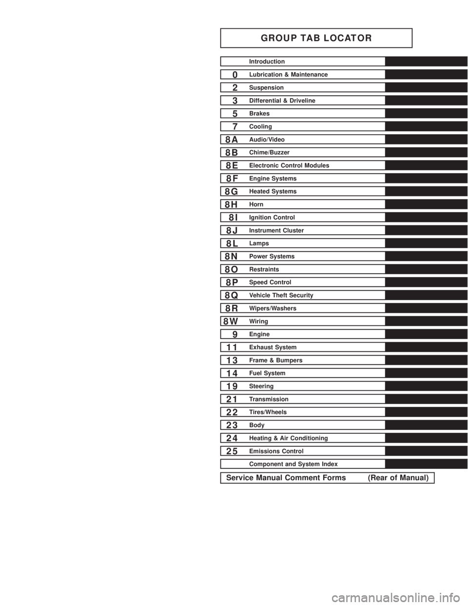
GROUP TAB LOCATOR
Introduction
0Lubrication & Maintenance
2Suspension
3Differential & Driveline
5Brakes
7Cooling
8AAudio/Video
8BChime/Buzzer
8EElectronic Control Modules
8FEngine Systems
8GHeated Systems
8HHorn
8IIgnition Control
8JInstrument Cluster
8LLamps
8NPower Systems
8ORestraints
8PSpeed Control
8QVehicle Theft Security
8RWipers/Washers
8WWiring
9Engine
11Exhaust System
13Frame & Bumpers
14Fuel System
19Steering
21Transmission
22Tires/Wheels
23Body
24Heating & Air Conditioning
25Emissions Control
Component and System Index
Service Manual Comment Forms (Rear of Manual)
Page 716 of 2305
LUBRICATION & MAINTENANCE
TABLE OF CONTENTS
page page
FLUID TYPES
DESCRIPTION
PARTS AND LUBRICANT
RECOMMENDATIONS...................1
AUTOMATIC TRANSMISSION FLUID - NAG1 . 1
AXLE FLUID..........................2
BRAKE FLUID.........................2
HOAT COOLANT.......................2
ENGINE OIL - DIESEL ENGINES...........3
FUEL REQUIREMENTS - DIESEL ENGINE . . . 4
POWER STEERING FLUID...............5
OPERATION - AUTOMATIC TRANSMISSION
FLUID...............................5
FLUID CAPACITIES
SPECIFICATIONS - FLUID CAPACITIES.......5FLUID FILL/CHECK LOCATIONS
INSPECTION - FLUID FILL/CHECK
LOCATIONS..........................5
HOISTING
STANDARD PROCEDURE - HOISTING........5
JUMP STARTING
STANDARD PROCEDURE - JUMP STARTING . . 6
TOWING
STANDARD PROCEDURE - TOWING.........7
MAINTENANCE SCHEDULES
DESCRIPTION..........................8
INTERNATIONAL SYMBOLS
DESCRIPTION..........................9
FLUID TYPES
DESCRIPTION
PARTS AND LUBRICANT RECOMMENDATIONS
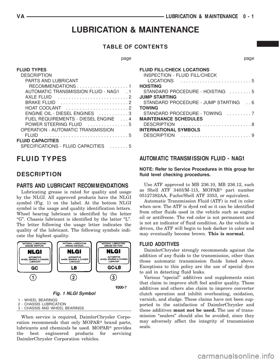
Lubricating grease is rated for quality and usage
by the NLGI. All approved products have the NLGI
symbol (Fig. 1) on the label. At the bottom NLGI
symbol is the usage and quality identification letters.
Wheel bearing lubricant is identified by the letter
ªGº. Chassis lubricant is identified by the latter ªLº.
The letter following the usage letter indicates the
quality of the lubricant. The following symbols indi-
cate the highest quality.
When service is required, DaimlerChrysler Corpo-
ration recommends that only MOPARtbrand parts,
lubricants and chemicals be used. MOPARtprovides
the best engineered products for servicing
DaimlerChrysler Corporation vehicles.
AUTOMATIC TRANSMISSION FLUID - NAG1
NOTE: Refer to Service Procedures in this group for
fluid level checking procedures.
Use ATF approved to MB 236.10, MB 236.12, such
as Shell ATF 3403/M-115, MOPARtpart number
05127382AA, Fuchs/Shell ATF 3353, or equivalent.
Automatic Transmission Fluid (ATF) is red in color
when new. The ATF is dyed red so it can be identified
from other fluids used in the vehicle such as engine
oil or antifreeze. The red color is not permanent and
is not an indicator of fluid condition. As the vehicle is
driven, the ATF will begin to look darker in color and
may eventually become brown.This is normal.
FLUID ADDITIVES
DaimlerChrysler strongly recommends against the
addition of any fluids to the transmission, other than
those automatic transmission fluids listed above.
Exceptions to this policy are the use of special dyes
to aid in detecting fluid leaks.
Various ªspecialº additives and supplements exist
that claim to improve shift feel and/or quality. These
additives and others also claim to improve converter
clutch operation and inhibit overheating, oxidation,
varnish, and sludge. These claims have not been sup-
ported to the satisfaction of DaimlerChrysler and
these additivesmust not be used.The use of trans-
mission ªsealersº should also be avoided, since they
may adversely affect the integrity of transmission
seals.
Fig. 1 NLGI Symbol
1 - WHEEL BEARINGS
2 - CHASSIS LUBRICATION
3 - CHASSIS AND WHEEL BEARINGS
VALUBRICATION & MAINTENANCE 0 - 1
Page 720 of 2305
Do not blend other specific fuel additives with die-
sel fuel. They only result in unnecessary cost, and
may be harmful to the engine operation.
POWER STEERING FLUID
No fluid service required. Filled with Power Steer-
ing Fluid approved to MB 236.3, such as Mobil
ATF-D (Exxon Mobil Corporation) or equivalent.
OPERATION - AUTOMATIC TRANSMISSION
FLUID
The automatic transmission fluid is selected based
upon several qualities. The fluid must provide a high
level of protection for the internal components by
providing a lubricating film between adjacent metal
components. The fluid must also be thermally stable
so that it can maintain a consistent viscosity through
a large temperature range. If the viscosity stays con-
stant through the temperature range of operation,
transmission operation and shift feel will remain con-
sistent. Transmission fluid must also be a good con-
ductor of heat. The fluid must absorb heat from the
internal transmission components and transfer that
heat to the transmission case.
FLUID CAPACITIES
SPECIFICATIONS - FLUID CAPACITIES
DESCRIPTION SPECIFICATION
ENGINE COOLANT
10 Liters 10.5 Quarts
ENGINE OIL
9.0L without Filter Re-
placement9.5 Quarts with Filter
Replacement
AUTOMATIC TRANSMISSION
Service Fill - NAG1 5.0 L (10.6 pts.)
O-haul Fill - NAG1 7.7 L (16.3 pts.)
Dry fill capacity Depending on type and size of inter-
nal cooler, length and inside diameter of cooler lines,
or use of an auxiliary cooler, these figures may vary.
(Refer to appropriate 21 - TRANSMISSION/AUTO-
MATIC/FLUID - STANDARD PROCEDURE).
REAR AXLE .03L (1 oz.)
8 1/2 1.8 L (4.0 pts.)
FUEL TANK
Primary 100 L (26.4 gal.)*
Reserve 10.5 L (2.8 gal.)*
*Nominal refill capacities are shown. A variation may
be observed from vehicle to vehicle due to manufac-
turing tolerance and refill procedure
DESCRIPTION SPECIFICATION
POWER STEERING SYSTEM
Power steering fluid capacities are dependent on
engine/chassis options as well as steering gear/cool-
er options. Depending on type and size of internal
cooler, length and inside diameter of cooler lines, or
use of an auxiliary cooler, these capacities may vary.
Refer to 19, Steering for proper fill and bleed proce-
dures.
FLUID FILL / CHECK LOCA-
TIONS
INSPECTION - FLUID FILL / CHECK LOCA-
TIONS
The fluid fill/check locations and lubrication points
are located in each applicable group.
HOISTING
STANDARD PROCEDURE - HOISTING
Refer to the Owner's Manual for emergency vehicle
lifting procedures.
WARNING: THE HOISTING AND JACK LIFTING
POINTS PROVIDED ARE FOR A COMPLETE VEHI-
CLE. WHEN A CHASSIS OR DRIVETRAIN COMPO-
NENT IS REMOVED FROM A VEHICLE, THE
CENTER OF GRAVITY IS ALTERED MAKING SOME
HOISTING CONDITIONS UNSTABLE. PROPERLY
SUPPORT OR SECURE VEHICLE TO HOISTING
DEVICE WHEN THESE CONDITIONS EXIST.
FLOOR JACK
When properly positioned, a floor jack can be used
to lift a vehicle. Support the vehicle in the raised
position with jack stands at the front and rear ends
of the frame rails.
CAUTION: Do not lift vehicle with a floor jack posi-
tioned under:
²An axle tube.
²A body side sill.
²A steering linkage component.
²A drive shaft.
²The engine or transmission oil pan.
²The fuel tank.
²A front suspension arm.
VALUBRICATION & MAINTENANCE 0 - 5
Page 722 of 2305
(6) Start the engine in the vehicle which has the
booster battery, let the engine idle a few minutes,
then start the engine in the vehicle with the dis-
charged battery.
CAUTION: Do not crank starter motor on disabled
vehicle for more than 15 seconds, starter will over-
heat and could fail.
(7) Allow battery in disabled vehicle to charge to
at least 12.4 volts (75% charge) before attempting to
start engine. If engine does not start within 15 sec-
onds, stop cranking engine and allow starter to cool
(15 min.), before cranking again.
DISCONNECT CABLE CLAMPS AS FOLLOWS:
²Disconnect BLACK cable clamp from engine
ground on disabled vehicle.
²When using a Booster vehicle, disconnect
BLACK cable clamp from battery negative terminal.
Disconnect RED cable clamp from battery positive
terminal.
²Disconnect RED cable clamp from battery posi-
tive terminal on disabled vehicle.
TOWING
STANDARD PROCEDURE - TOWING
WARNING: Do not tow the vehicle if the key cannot
be turned in the ignition lock. If the key cannot be
turned, the ignition lock remains locked and the
vehicle cannot be steered. With the engine not run-
ning there is no power assistance for the braking
and steering systems. In this case, it is important to
keep in mind that a considerably higher degree of
effort is necessary to brake and steer the vehicle.
The vehicle must not be towed with the front axle
raised and the key in position 2 in the ignition lock
as the drive wheels could then lock due to the
acceleration skid control (ASR)
If the Engine is Damaged
For towing distances up to 30 miles (about 50
km)
²Shift selector lever in ªNº position.
²Do not exceed a towing speed of 30 m.p.h. (50
km/h).
For towing distances greater than 30 mile
(about 50 km)
²Remove the propeller shafts leading to the drive
axles. The vehicle can be towed without restriction.
If the Transmission is Damaged
²Remove the propeller shafts leading to the drive
axles. The vehicle can be towed without restriction.
If the Front Axle is Damaged
²Raise the front axle.
²Observe the same towing restrictions as for
engine damage.
If the Rear Axle is Damaged
²Raise the rear axle.
NOTE: Comply with local legal regulations regard-
ing towing vehicles.
SAFETY PRECAUTIONS
NOTE: The following safety precautions must be
observed when towing a vehicle.
²Secure loose and protruding parts.
²Always use a safety chain system that is inde-
pendent of the lifting and towing equipment.
²Do not allow towing equipment to contact the
disabled vehicle's fuel tank.
²Do not allow anyone under the disabled vehicle
while it is lifted by the towing device.
²Do not allow passengers to ride in a vehicle
being towed.
²Always observe state and local laws regarding
towing regulations.
²Do not tow a vehicle in a manner that could
jeopardize the safety of the operator, pedestrians or
other motorists.
²Do not attach tow chains, T-hooks, J-hooks, or a
tow sling to a bumper, steering linkage, drive shafts
or a non-reinforced frame hole.
²Remove exhaust pipe tips that interfere with the
tow sling and crossbar
²Padding should be placed between the tow sling/
crossbar and any painted surfaces
²When placing tow hooks on the rear axle, posi-
tion them so they do not damage the brake tubing or
hoses
²Do not tow the vehicle by connecting to the front
or rear shock absorbers
²Do not tow a heavily loaded vehicle. Damage to
the vehicle may result. Use a flatbed device to trans-
port a loaded vehicle.
GROUND CLEARANCE
CAUTION: If vehicle is towed with wheels removed,
install lug nuts to retain brake drums.
A towed vehicle should be raised until lifted wheels
are a minimum 100 mm (4 in) from the ground. Be
sure there is adequate ground clearance at the oppo-
site end of the vehicle, especially when towing over
rough terrain, steep rises in the road or if the vehicle
is equipped with air dams, spoilers, and/or ground
VALUBRICATION & MAINTENANCE 0 - 7
Page 724 of 2305
SCOPE OF WORK FOR MAINTENANCE SERVICE
Oil Service
²Engine: Oil change and filter replacement
Check fluid levels of the following system, refill as neces-
sary.
²If fluid is lost, trace and eliminate cause - as a
separate order.
²Power-assisted steering
Lubrication work:
²Trailer tow hitch (original equipment)
Maintenance
²ASSYST maintenance computer reset
Function check
²Signalling system, warning and indicator lamps
²Headlamps, exterior lighting
²Windshield wipers, windshield washer system
Check for leaks and damage
²Check for abrasion points and ensure that lines
are correctly routed!
²All lines and hoses, sensor cables
²Rubber boots on front axle drive shafts, rubber
boots on front axle suspension ball joints, shock
absorbers
²Check fluid levels for the following systems, cor-
rect as necessary
NOTE: Should there be a loss of fluid which cannot
be explained by regular use, trace and eliminate the
cause.
²Engine cooling system. Check corrosion inhibi-
tor/antifreeze, refill as necessary.
²Hydraulic brake system
²Battery
²Windshield washer system
Engine
²Fuel filter renewal - Every oil service
²Air cleaner with maintenance indicator:
²Check degree of contamination.
²Air cleaner filter element renewed as necessary.
Chassis and body
²Trailer coupling: Check operation, play and
retaining fixtures
²Secondary rubber springs: Visual check
²Tire pressures: Correct as necessary, including
spare tire
²Check thickness of brake pads
²Brake test
²Check condition of steering mechanism
²Heating/ventilation dust filter renewal
ADDITIONAL MAINTENANCE WORK
Automatic transmission once only at 80,000 miles / 128000
km
²Oil and filter change
During every second maintenance service
²Air cleaner without maintenance indicator:
²Air cleaner filter element renewal
²Check poly-V-belt for wear and signs of damage
During every fourth maintenance service
²Change rear axle fluid
ADDITIONAL MAINTENANCE WORK AFTER YEARS
Every 2 years
²Change brake fluid.
Every 3 years
²Air cleaner filter element renewal (note installa-
tion date)
Every 15 years or 100,000 miles
²Coolant renewal
²Note coolant composition
INTERNATIONAL SYMBOLS
DESCRIPTION
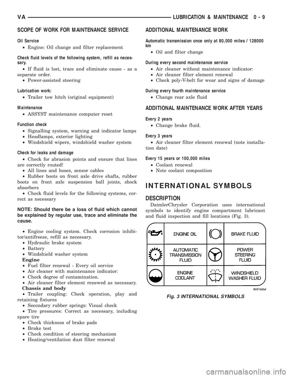
DaimlerChrysler Corporation uses international
symbols to identify engine compartment lubricant
and fluid inspection and fill locations (Fig. 3).
Fig. 3 INTERNATIONAL SYMBOLS
VALUBRICATION & MAINTENANCE 0 - 9