relay MERCEDES-BENZ SPRINTER 2006 User Guide
[x] Cancel search | Manufacturer: MERCEDES-BENZ, Model Year: 2006, Model line: SPRINTER, Model: MERCEDES-BENZ SPRINTER 2006Pages: 2305, PDF Size: 48.12 MB
Page 88 of 2305
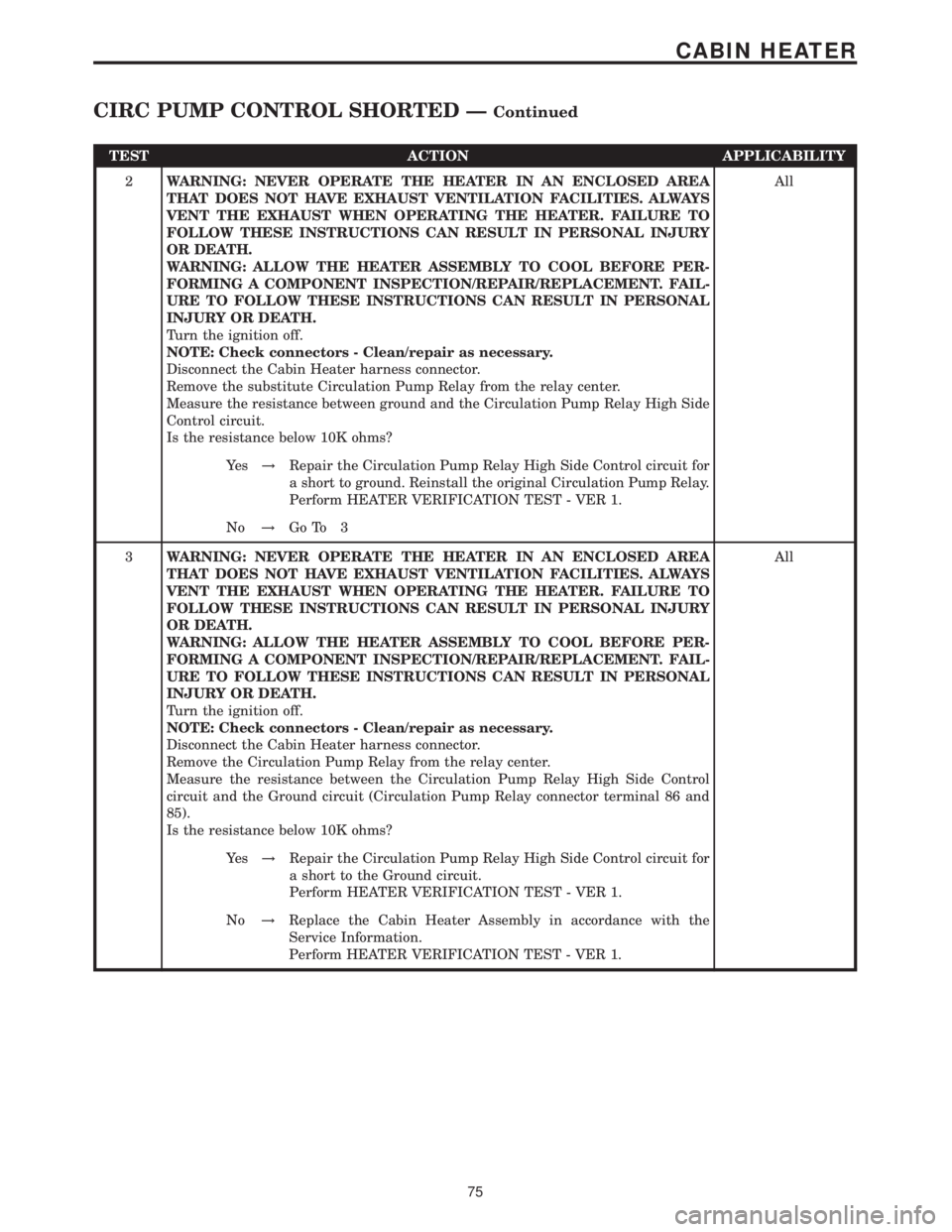
TEST ACTION APPLICABILITY
2WARNING: NEVER OPERATE THE HEATER IN AN ENCLOSED AREA
THAT DOES NOT HAVE EXHAUST VENTILATION FACILITIES. ALWAYS
VENT THE EXHAUST WHEN OPERATING THE HEATER. FAILURE TO
FOLLOW THESE INSTRUCTIONS CAN RESULT IN PERSONAL INJURY
OR DEATH.
WARNING: ALLOW THE HEATER ASSEMBLY TO COOL BEFORE PER-
FORMING A COMPONENT INSPECTION/REPAIR/REPLACEMENT. FAIL-
URE TO FOLLOW THESE INSTRUCTIONS CAN RESULT IN PERSONAL
INJURY OR DEATH.
Turn the ignition off.
NOTE: Check connectors - Clean/repair as necessary.
Disconnect the Cabin Heater harness connector.
Remove the substitute Circulation Pump Relay from the relay center.
Measure the resistance between ground and the Circulation Pump Relay High Side
Control circuit.
Is the resistance below 10K ohms?All
Ye s!Repair the Circulation Pump Relay High Side Control circuit for
a short to ground. Reinstall the original Circulation Pump Relay.
Perform HEATER VERIFICATION TEST - VER 1.
No!Go To 3
3WARNING: NEVER OPERATE THE HEATER IN AN ENCLOSED AREA
THAT DOES NOT HAVE EXHAUST VENTILATION FACILITIES. ALWAYS
VENT THE EXHAUST WHEN OPERATING THE HEATER. FAILURE TO
FOLLOW THESE INSTRUCTIONS CAN RESULT IN PERSONAL INJURY
OR DEATH.
WARNING: ALLOW THE HEATER ASSEMBLY TO COOL BEFORE PER-
FORMING A COMPONENT INSPECTION/REPAIR/REPLACEMENT. FAIL-
URE TO FOLLOW THESE INSTRUCTIONS CAN RESULT IN PERSONAL
INJURY OR DEATH.
Turn the ignition off.
NOTE: Check connectors - Clean/repair as necessary.
Disconnect the Cabin Heater harness connector.
Remove the Circulation Pump Relay from the relay center.
Measure the resistance between the Circulation Pump Relay High Side Control
circuit and the Ground circuit (Circulation Pump Relay connector terminal 86 and
85).
Is the resistance below 10K ohms?All
Ye s!Repair the Circulation Pump Relay High Side Control circuit for
a short to the Ground circuit.
Perform HEATER VERIFICATION TEST - VER 1.
No!Replace the Cabin Heater Assembly in accordance with the
Service Information.
Perform HEATER VERIFICATION TEST - VER 1.
75
CABIN HEATER
CIRC PUMP CONTROL SHORTED ÐContinued
Page 96 of 2305
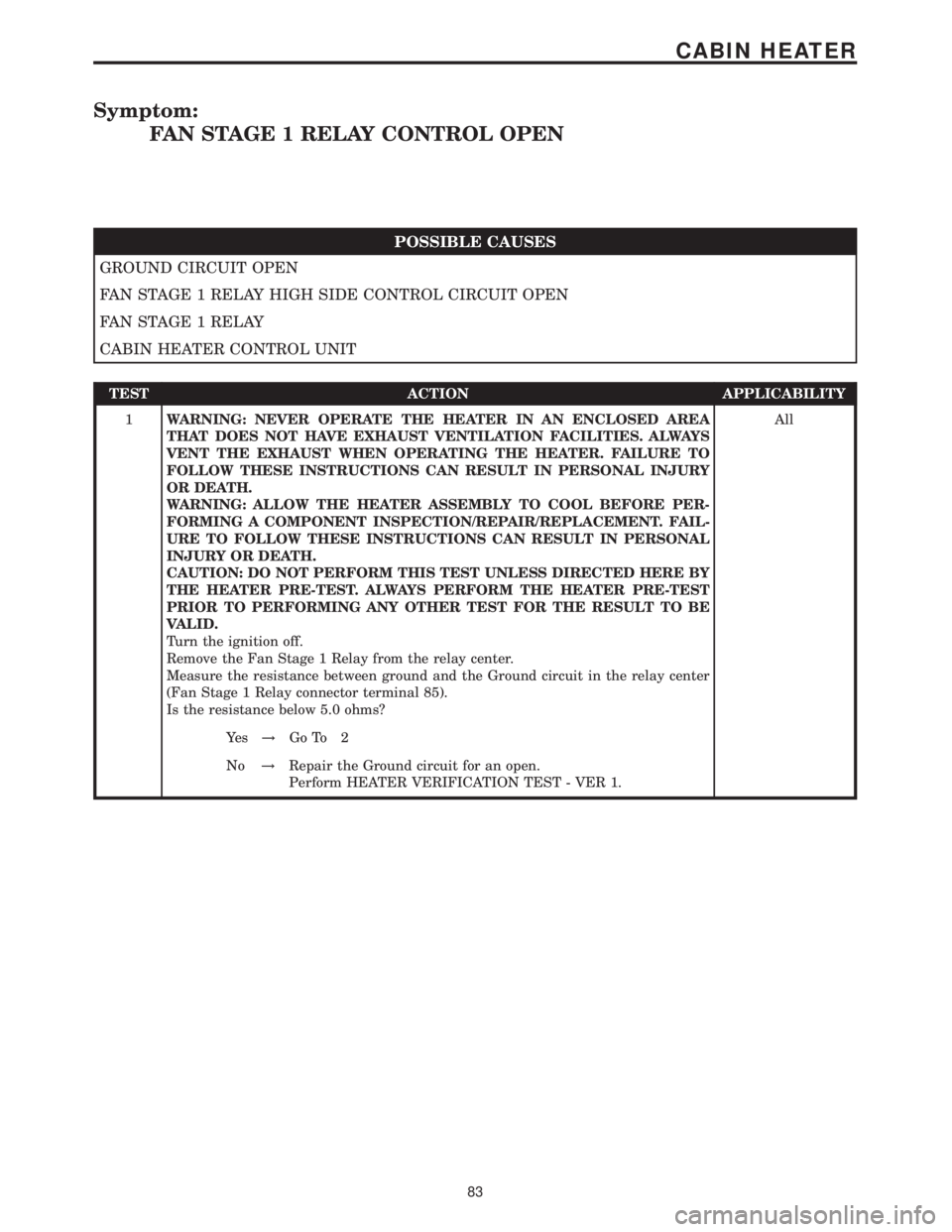
Symptom:
FAN STAGE 1 RELAY CONTROL OPEN
POSSIBLE CAUSES
GROUND CIRCUIT OPEN
FAN STAGE 1 RELAY HIGH SIDE CONTROL CIRCUIT OPEN
FAN STAGE 1 RELAY
CABIN HEATER CONTROL UNIT
TEST ACTION APPLICABILITY
1WARNING: NEVER OPERATE THE HEATER IN AN ENCLOSED AREA
THAT DOES NOT HAVE EXHAUST VENTILATION FACILITIES. ALWAYS
VENT THE EXHAUST WHEN OPERATING THE HEATER. FAILURE TO
FOLLOW THESE INSTRUCTIONS CAN RESULT IN PERSONAL INJURY
OR DEATH.
WARNING: ALLOW THE HEATER ASSEMBLY TO COOL BEFORE PER-
FORMING A COMPONENT INSPECTION/REPAIR/REPLACEMENT. FAIL-
URE TO FOLLOW THESE INSTRUCTIONS CAN RESULT IN PERSONAL
INJURY OR DEATH.
CAUTION: DO NOT PERFORM THIS TEST UNLESS DIRECTED HERE BY
THE HEATER PRE-TEST. ALWAYS PERFORM THE HEATER PRE-TEST
PRIOR TO PERFORMING ANY OTHER TEST FOR THE RESULT TO BE
VALID.
Turn the ignition off.
Remove the Fan Stage 1 Relay from the relay center.
Measure the resistance between ground and the Ground circuit in the relay center
(Fan Stage 1 Relay connector terminal 85).
Is the resistance below 5.0 ohms?All
Ye s!Go To 2
No!Repair the Ground circuit for an open.
Perform HEATER VERIFICATION TEST - VER 1.
83
CABIN HEATER
Page 97 of 2305
TEST ACTION APPLICABILITY
2WARNING: NEVER OPERATE THE HEATER IN AN ENCLOSED AREA
THAT DOES NOT HAVE EXHAUST VENTILATION FACILITIES. ALWAYS
VENT THE EXHAUST WHEN OPERATING THE HEATER. FAILURE TO
FOLLOW THESE INSTRUCTIONS CAN RESULT IN PERSONAL INJURY
OR DEATH.
WARNING: ALLOW THE HEATER ASSEMBLY TO COOL BEFORE PER-
FORMING A COMPONENT INSPECTION/REPAIR/REPLACEMENT. FAIL-
URE TO FOLLOW THESE INSTRUCTIONS CAN RESULT IN PERSONAL
INJURY OR DEATH.
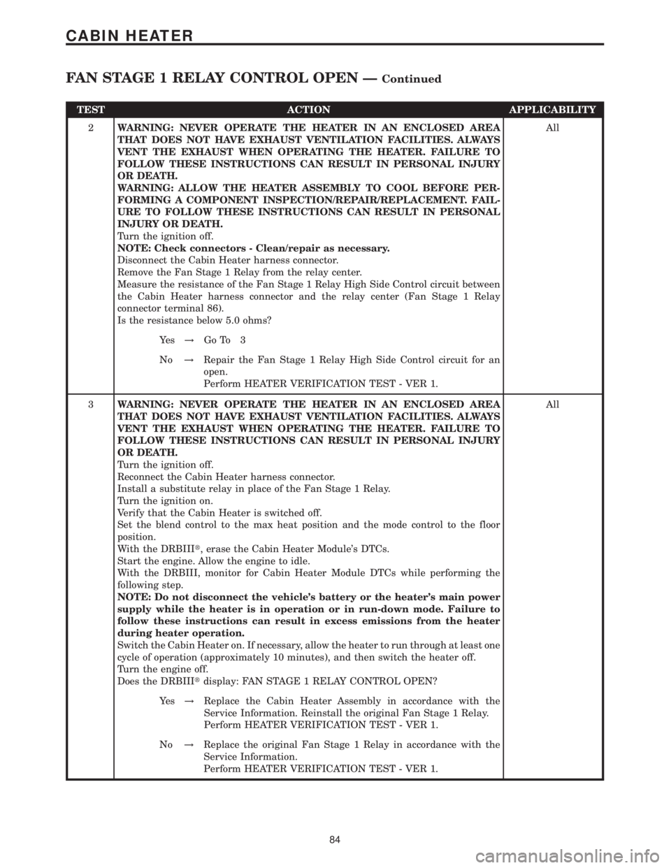
Turn the ignition off.
NOTE: Check connectors - Clean/repair as necessary.
Disconnect the Cabin Heater harness connector.
Remove the Fan Stage 1 Relay from the relay center.
Measure the resistance of the Fan Stage 1 Relay High Side Control circuit between
the Cabin Heater harness connector and the relay center (Fan Stage 1 Relay
connector terminal 86).
Is the resistance below 5.0 ohms?All
Ye s!Go To 3
No!Repair the Fan Stage 1 Relay High Side Control circuit for an
open.
Perform HEATER VERIFICATION TEST - VER 1.
3WARNING: NEVER OPERATE THE HEATER IN AN ENCLOSED AREA
THAT DOES NOT HAVE EXHAUST VENTILATION FACILITIES. ALWAYS
VENT THE EXHAUST WHEN OPERATING THE HEATER. FAILURE TO
FOLLOW THESE INSTRUCTIONS CAN RESULT IN PERSONAL INJURY
OR DEATH.
Turn the ignition off.
Reconnect the Cabin Heater harness connector.
Install a substitute relay in place of the Fan Stage 1 Relay.
Turn the ignition on.
Verify that the Cabin Heater is switched off.
Set the blend control to the max heat position and the mode control to the floor
position.
With the DRBIIIt, erase the Cabin Heater Module's DTCs.
Start the engine. Allow the engine to idle.
With the DRBIII, monitor for Cabin Heater Module DTCs while performing the
following step.
NOTE: Do not disconnect the vehicle's battery or the heater's main power
supply while the heater is in operation or in run-down mode. Failure to
follow these instructions can result in excess emissions from the heater
during heater operation.
Switch the Cabin Heater on. If necessary, allow the heater to run through at least one
cycle of operation (approximately 10 minutes), and then switch the heater off.
Turn the engine off.
Does the DRBIIItdisplay: FAN STAGE 1 RELAY CONTROL OPEN?All
Ye s!Replace the Cabin Heater Assembly in accordance with the
Service Information. Reinstall the original Fan Stage 1 Relay.
Perform HEATER VERIFICATION TEST - VER 1.
No!Replace the original Fan Stage 1 Relay in accordance with the
Service Information.
Perform HEATER VERIFICATION TEST - VER 1.
84
CABIN HEATER
FAN STAGE 1 RELAY CONTROL OPEN ÐContinued
Page 98 of 2305
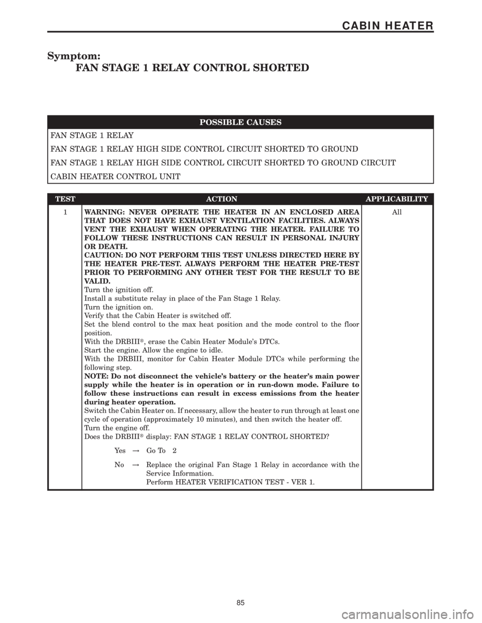
Symptom:
FAN STAGE 1 RELAY CONTROL SHORTED
POSSIBLE CAUSES
FAN STAGE 1 RELAY
FAN STAGE 1 RELAY HIGH SIDE CONTROL CIRCUIT SHORTED TO GROUND
FAN STAGE 1 RELAY HIGH SIDE CONTROL CIRCUIT SHORTED TO GROUND CIRCUIT
CABIN HEATER CONTROL UNIT
TEST ACTION APPLICABILITY
1WARNING: NEVER OPERATE THE HEATER IN AN ENCLOSED AREA
THAT DOES NOT HAVE EXHAUST VENTILATION FACILITIES. ALWAYS
VENT THE EXHAUST WHEN OPERATING THE HEATER. FAILURE TO
FOLLOW THESE INSTRUCTIONS CAN RESULT IN PERSONAL INJURY
OR DEATH.
CAUTION: DO NOT PERFORM THIS TEST UNLESS DIRECTED HERE BY
THE HEATER PRE-TEST. ALWAYS PERFORM THE HEATER PRE-TEST
PRIOR TO PERFORMING ANY OTHER TEST FOR THE RESULT TO BE
VALID.
Turn the ignition off.
Install a substitute relay in place of the Fan Stage 1 Relay.
Turn the ignition on.
Verify that the Cabin Heater is switched off.
Set the blend control to the max heat position and the mode control to the floor
position.
With the DRBIIIt, erase the Cabin Heater Module's DTCs.
Start the engine. Allow the engine to idle.
With the DRBIII, monitor for Cabin Heater Module DTCs while performing the
following step.
NOTE: Do not disconnect the vehicle's battery or the heater's main power
supply while the heater is in operation or in run-down mode. Failure to
follow these instructions can result in excess emissions from the heater
during heater operation.
Switch the Cabin Heater on. If necessary, allow the heater to run through at least one
cycle of operation (approximately 10 minutes), and then switch the heater off.
Turn the engine off.
Does the DRBIIItdisplay: FAN STAGE 1 RELAY CONTROL SHORTED?All
Ye s!Go To 2
No!Replace the original Fan Stage 1 Relay in accordance with the
Service Information.
Perform HEATER VERIFICATION TEST - VER 1.
85
CABIN HEATER
Page 99 of 2305
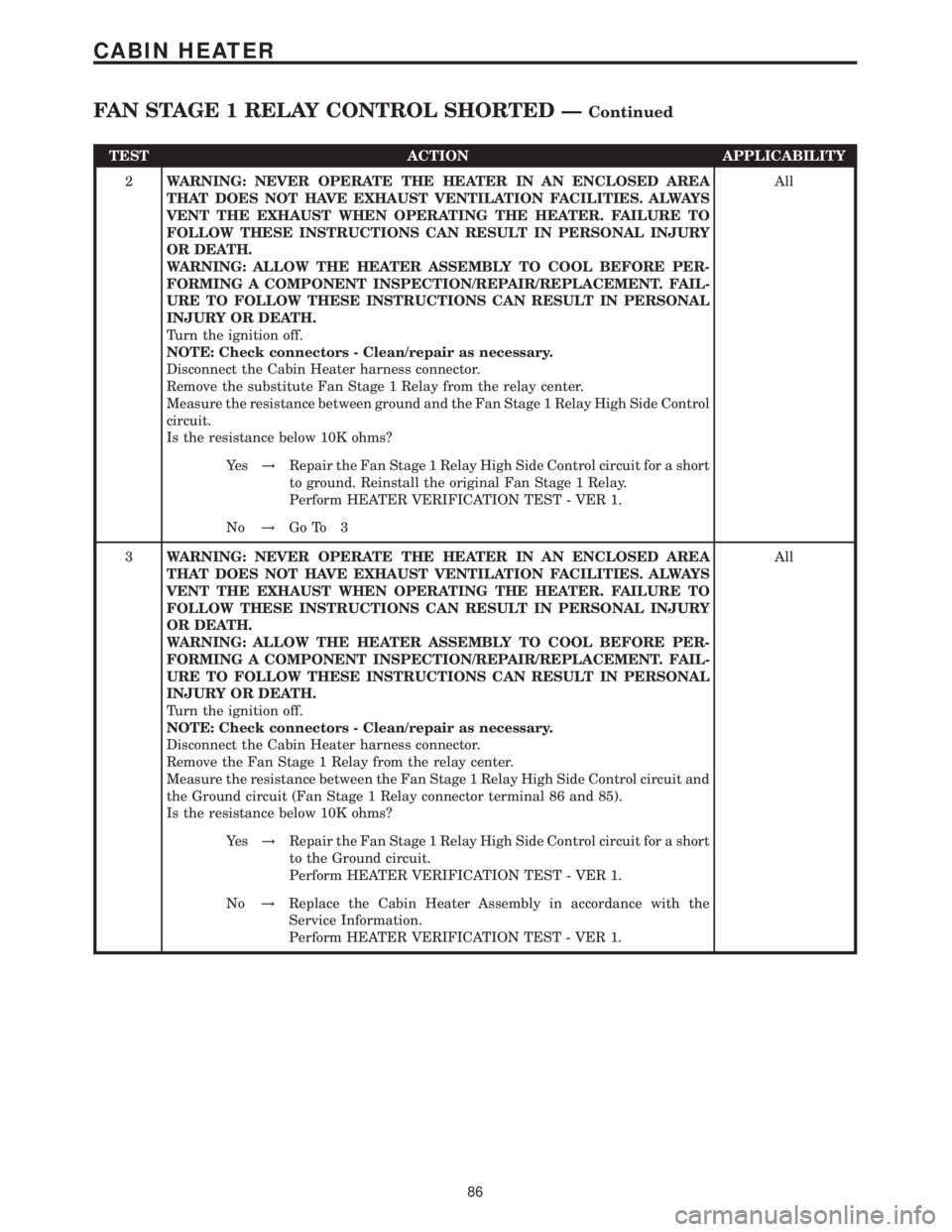
TEST ACTION APPLICABILITY
2WARNING: NEVER OPERATE THE HEATER IN AN ENCLOSED AREA
THAT DOES NOT HAVE EXHAUST VENTILATION FACILITIES. ALWAYS
VENT THE EXHAUST WHEN OPERATING THE HEATER. FAILURE TO
FOLLOW THESE INSTRUCTIONS CAN RESULT IN PERSONAL INJURY
OR DEATH.
WARNING: ALLOW THE HEATER ASSEMBLY TO COOL BEFORE PER-
FORMING A COMPONENT INSPECTION/REPAIR/REPLACEMENT. FAIL-
URE TO FOLLOW THESE INSTRUCTIONS CAN RESULT IN PERSONAL
INJURY OR DEATH.
Turn the ignition off.
NOTE: Check connectors - Clean/repair as necessary.
Disconnect the Cabin Heater harness connector.
Remove the substitute Fan Stage 1 Relay from the relay center.
Measure the resistance between ground and the Fan Stage 1 Relay High Side Control
circuit.
Is the resistance below 10K ohms?All
Ye s!Repair the Fan Stage 1 Relay High Side Control circuit for a short
to ground. Reinstall the original Fan Stage 1 Relay.
Perform HEATER VERIFICATION TEST - VER 1.
No!Go To 3
3WARNING: NEVER OPERATE THE HEATER IN AN ENCLOSED AREA
THAT DOES NOT HAVE EXHAUST VENTILATION FACILITIES. ALWAYS
VENT THE EXHAUST WHEN OPERATING THE HEATER. FAILURE TO
FOLLOW THESE INSTRUCTIONS CAN RESULT IN PERSONAL INJURY
OR DEATH.
WARNING: ALLOW THE HEATER ASSEMBLY TO COOL BEFORE PER-
FORMING A COMPONENT INSPECTION/REPAIR/REPLACEMENT. FAIL-
URE TO FOLLOW THESE INSTRUCTIONS CAN RESULT IN PERSONAL
INJURY OR DEATH.
Turn the ignition off.
NOTE: Check connectors - Clean/repair as necessary.
Disconnect the Cabin Heater harness connector.
Remove the Fan Stage 1 Relay from the relay center.
Measure the resistance between the Fan Stage 1 Relay High Side Control circuit and
the Ground circuit (Fan Stage 1 Relay connector terminal 86 and 85).
Is the resistance below 10K ohms?All
Ye s!Repair the Fan Stage 1 Relay High Side Control circuit for a short
to the Ground circuit.
Perform HEATER VERIFICATION TEST - VER 1.
No!Replace the Cabin Heater Assembly in accordance with the
Service Information.
Perform HEATER VERIFICATION TEST - VER 1.
86
CABIN HEATER
FAN STAGE 1 RELAY CONTROL SHORTED ÐContinued
Page 143 of 2305
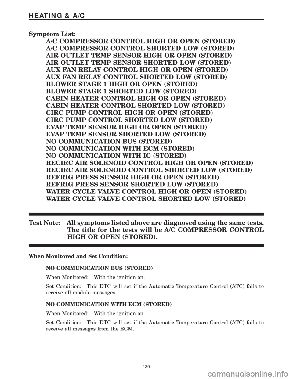
Symptom List:
A/C COMPRESSOR CONTROL HIGH OR OPEN (STORED)
A/C COMPRESSOR CONTROL SHORTED LOW (STORED)
AIR OUTLET TEMP SENSOR HIGH OR OPEN (STORED)
AIR OUTLET TEMP SENSOR SHORTED LOW (STORED)
AUX FAN RELAY CONTROL HIGH OR OPEN (STORED)
AUX FAN RELAY CONTROL SHORTED LOW (STORED)
BLOWER STAGE 1 HIGH OR OPEN (STORED)
BLOWER STAGE 1 SHORTED LOW (STORED)
CABIN HEATER CONTROL HIGH OR OPEN (STORED)
CABIN HEATER CONTROL SHORTED LOW (STORED)
CIRC PUMP CONTROL HIGH OR OPEN (STORED)
CIRC PUMP CONTROL SHORTED LOW (STORED)
EVAP TEMP SENSOR HIGH OR OPEN (STORED)
EVAP TEMP SENSOR SHORTED LOW (STORED)
NO COMMUNICATION BUS (STORED)
NO COMMUNICATION WITH ECM (STORED)
NO COMMUNICATION WITH IC (STORED)
RECIRC AIR SOLENOID CONTROL HIGH OR OPEN (STORED)
RECIRC AIR SOLENOID CONTROL SHORTED LOW (STORED)
REFRIG PRESS SENSOR HIGH OR OPEN (STORED)
REFRIG PRESS SENSOR SHORTED LOW (STORED)
WATER CYCLE VALVE CONTROL HIGH OR OPEN (STORED)
WATER CYCLE VALVE CONTROL SHORTED LOW (STORED)
Test Note: All symptoms listed above are diagnosed using the same tests.
The title for the tests will be A/C COMPRESSOR CONTROL
HIGH OR OPEN (STORED).
When Monitored and Set Condition:
NO COMMUNICATION BUS (STORED)
When Monitored: With the ignition on.
Set Condition: This DTC will set if the Automatic Temperature Control (ATC) fails to
receive all module messages.
NO COMMUNICATION WITH ECM (STORED)
When Monitored: With the ignition on.
Set Condition: This DTC will set if the Automatic Temperature Control (ATC) fails to
receive all messages from the ECM.
130
HEATING & A/C
Page 153 of 2305
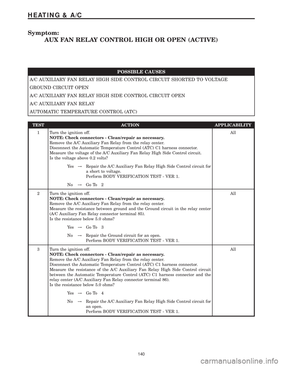
Symptom:
AUX FAN RELAY CONTROL HIGH OR OPEN (ACTIVE)
POSSIBLE CAUSES
A/C AUXILIARY FAN RELAY HIGH SIDE CONTROL CIRCUIT SHORTED TO VOLTAGE
GROUND CIRCUIT OPEN
A/C AUXILIARY FAN RELAY HIGH SIDE CONTROL CIRCUIT OPEN
A/C AUXILIARY FAN RELAY
AUTOMATIC TEMPERATURE CONTROL (ATC)
TEST ACTION APPLICABILITY
1 Turn the ignition off.
NOTE: Check connectors - Clean/repair as necessary.
Remove the A/C Auxiliary Fan Relay from the relay center.
Disconnect the Automatic Temperature Control (ATC) C1 harness connector.
Measure the voltage of the A/C Auxiliary Fan Relay High Side Control circuit.
Is the voltage above 0.2 volts?All
Ye s!Repair the A/C Auxiliary Fan Relay High Side Control circuit for
a short to voltage.
Perform BODY VERIFICATION TEST - VER 1.
No!Go To 2
2 Turn the ignition off.
NOTE: Check connectors - Clean/repair as necessary.
Remove the A/C Auxiliary Fan Relay from the relay center.
Measure the resistance between ground and the Ground circuit in the relay center
(A/C Auxiliary Fan Relay connector terminal 85).
Is the resistance below 5.0 ohms?All
Ye s!Go To 3
No!Repair the Ground circuit for an open.
Perform BODY VERIFICATION TEST - VER 1.
3 Turn the ignition off.
NOTE: Check connectors - Clean/repair as necessary.
Remove the A/C Auxiliary Fan Relay from the relay center.
Disconnect the Automatic Temperature Control (ATC) C1 harness connector.
Measure the resistance of the A/C Auxiliary Fan Relay High Side Control circuit
between the Automatic Temperature Control (ATC) C1 harness connector and the
relay center (A/C Auxiliary Fan Relay connector terminal 86).
Is the resistance below 5.0 ohms?All
Ye s!Go To 4
No!Repair the A/C Auxiliary Fan Relay High Side Control circuit for
an open.
Perform BODY VERIFICATION TEST - VER 1.
140
HEATING & A/C
Page 154 of 2305
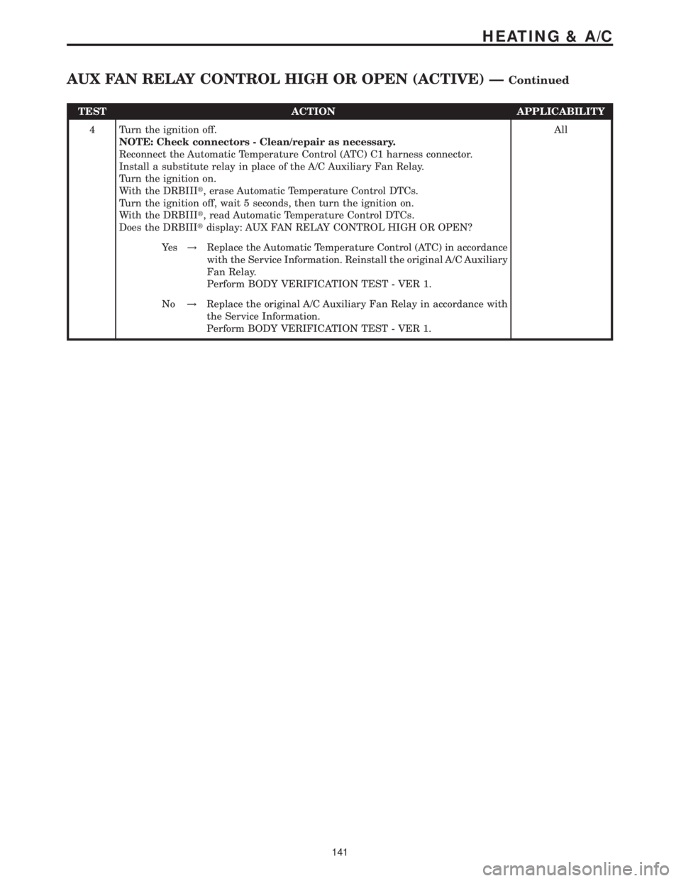
TEST ACTION APPLICABILITY
4 Turn the ignition off.
NOTE: Check connectors - Clean/repair as necessary.
Reconnect the Automatic Temperature Control (ATC) C1 harness connector.
Install a substitute relay in place of the A/C Auxiliary Fan Relay.
Turn the ignition on.
With the DRBIIIt, erase Automatic Temperature Control DTCs.
Turn the ignition off, wait 5 seconds, then turn the ignition on.
With the DRBIIIt, read Automatic Temperature Control DTCs.
Does the DRBIIItdisplay: AUX FAN RELAY CONTROL HIGH OR OPEN?All
Ye s!Replace the Automatic Temperature Control (ATC) in accordance
with the Service Information. Reinstall the original A/C Auxiliary
Fan Relay.
Perform BODY VERIFICATION TEST - VER 1.
No!Replace the original A/C Auxiliary Fan Relay in accordance with
the Service Information.
Perform BODY VERIFICATION TEST - VER 1.
141
HEATING & A/C
AUX FAN RELAY CONTROL HIGH OR OPEN (ACTIVE) ÐContinued
Page 155 of 2305
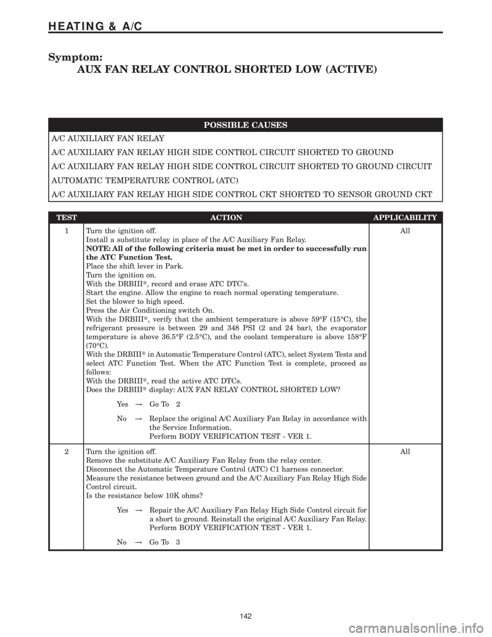
Symptom:
AUX FAN RELAY CONTROL SHORTED LOW (ACTIVE)
POSSIBLE CAUSES
A/C AUXILIARY FAN RELAY
A/C AUXILIARY FAN RELAY HIGH SIDE CONTROL CIRCUIT SHORTED TO GROUND
A/C AUXILIARY FAN RELAY HIGH SIDE CONTROL CIRCUIT SHORTED TO GROUND CIRCUIT
AUTOMATIC TEMPERATURE CONTROL (ATC)
A/C AUXILIARY FAN RELAY HIGH SIDE CONTROL CKT SHORTED TO SENSOR GROUND CKT
TEST ACTION APPLICABILITY
1 Turn the ignition off.
Install a substitute relay in place of the A/C Auxiliary Fan Relay.
NOTE: All of the following criteria must be met in order to successfully run
the ATC Function Test.
Place the shift lever in Park.
Turn the ignition on.
With the DRBIIIt, record and erase ATC DTC's.
Start the engine. Allow the engine to reach normal operating temperature.
Set the blower to high speed.
Press the Air Conditioning switch On.
With the DRBIIIt, verify that the ambient temperature is above 59ÉF (15ÉC), the
refrigerant pressure is between 29 and 348 PSI (2 and 24 bar), the evaporator
temperature is above 36.5ÉF (2.5ÉC), and the coolant temperature is above 158ÉF
(70ÉC).
With the DRBIIItin Automatic Temperature Control (ATC), select System Tests and
select ATC Function Test. When the ATC Function Test is complete, proceed as
follows:
With the DRBIIIt, read the active ATC DTCs.
Does the DRBIIItdisplay: AUX FAN RELAY CONTROL SHORTED LOW?All
Ye s!Go To 2
No!Replace the original A/C Auxiliary Fan Relay in accordance with
the Service Information.
Perform BODY VERIFICATION TEST - VER 1.
2 Turn the ignition off.
Remove the substitute A/C Auxiliary Fan Relay from the relay center.
Disconnect the Automatic Temperature Control (ATC) C1 harness connector.
Measure the resistance between ground and the A/C Auxiliary Fan Relay High Side
Control circuit.
Is the resistance below 10K ohms?All
Ye s!Repair the A/C Auxiliary Fan Relay High Side Control circuit for
a short to ground. Reinstall the original A/C Auxiliary Fan Relay.
Perform BODY VERIFICATION TEST - VER 1.
No!Go To 3
142
HEATING & A/C
Page 156 of 2305
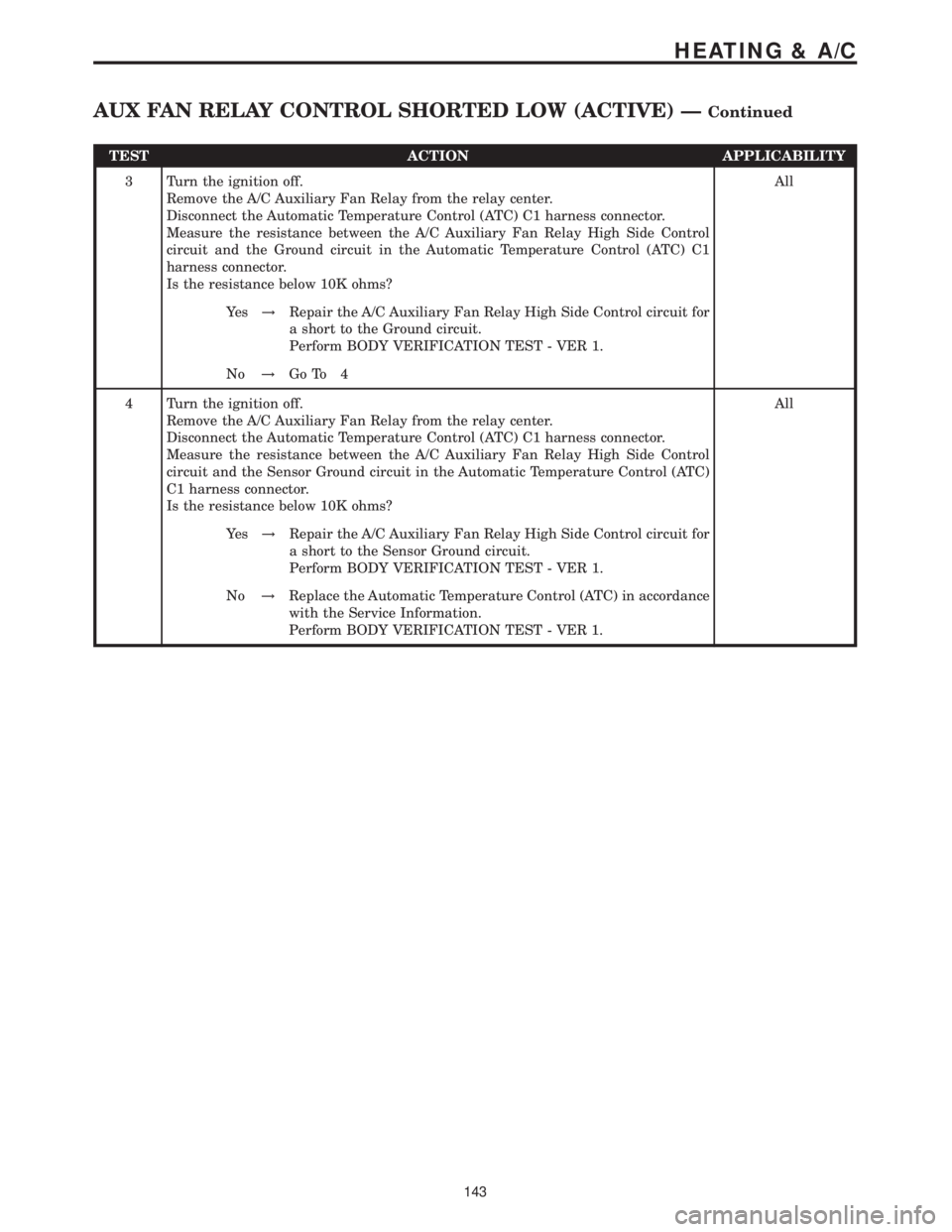
TEST ACTION APPLICABILITY
3 Turn the ignition off.
Remove the A/C Auxiliary Fan Relay from the relay center.
Disconnect the Automatic Temperature Control (ATC) C1 harness connector.
Measure the resistance between the A/C Auxiliary Fan Relay High Side Control
circuit and the Ground circuit in the Automatic Temperature Control (ATC) C1
harness connector.
Is the resistance below 10K ohms?All
Ye s!Repair the A/C Auxiliary Fan Relay High Side Control circuit for
a short to the Ground circuit.
Perform BODY VERIFICATION TEST - VER 1.
No!Go To 4
4 Turn the ignition off.
Remove the A/C Auxiliary Fan Relay from the relay center.
Disconnect the Automatic Temperature Control (ATC) C1 harness connector.
Measure the resistance between the A/C Auxiliary Fan Relay High Side Control
circuit and the Sensor Ground circuit in the Automatic Temperature Control (ATC)
C1 harness connector.
Is the resistance below 10K ohms?All
Ye s!Repair the A/C Auxiliary Fan Relay High Side Control circuit for
a short to the Sensor Ground circuit.
Perform BODY VERIFICATION TEST - VER 1.
No!Replace the Automatic Temperature Control (ATC) in accordance
with the Service Information.
Perform BODY VERIFICATION TEST - VER 1.
143
HEATING & A/C
AUX FAN RELAY CONTROL SHORTED LOW (ACTIVE) ÐContinued