water pump MERCEDES-BENZ SPRINTER 2006 Service Manual
[x] Cancel search | Manufacturer: MERCEDES-BENZ, Model Year: 2006, Model line: SPRINTER, Model: MERCEDES-BENZ SPRINTER 2006Pages: 2305, PDF Size: 48.12 MB
Page 8 of 2305
TABLE OF CONTENTS - Continued
FLAME SENSOR SHORTED..............................................91
GLOW PIN OPEN.......................................................91
GLOW PIN SHORTED...................................................91
HEATER IN LOCKOUT MODE.............................................93
HEATER OVERHEATED..................................................93
SUCCESSIVE OVERHEATING............................................93
OVER VOLTAGE........................................................96
OVERHEATING SENSOR OPEN...........................................97
OVERHEATING SENSOR SHORTED.......................................97
TEMP SENSOR OPEN...................................................98
TEMP SENSOR SHORTED...............................................98
UNDER VOLTAGE......................................................99
COMMUNICATION
*NO RESPONSE FROM AIRBAG CONTROL MODULE.......................102
*NO RESPONSE FROM AUTOMATIC TEMPERATURE CONTROL..............104
*NO RESPONSE FROM CABIN HEATER MODULE..........................106
*NO RESPONSE FROM CENTRAL TIMER MODULE.........................108
*NO RESPONSE FROM CONTROLLER ANTILOCK BRAKE...................110
*NO RESPONSE FROM ENGINE CONTROL MODULE.......................112
*NO RESPONSE FROM HEATER BOOSTER MODULE.......................114
*NO RESPONSE FROM INSTRUMENT CLUSTER...........................116
*NO RESPONSE FROM RADIO..........................................118
*NO RESPONSE FROM SECURITY SYSTEM MODULE......................120
*NO RESPONSE FROM SENTRY KEY REMOTE ENTRY MODULE.............122
*NO RESPONSE FROM SHIFTER ASSEMBLY..............................124
*NO RESPONSE FROM TRANSMISSION CONTROL MODULE................126
HEATING & A/C
A/C COMPRESSOR CONTROL HIGH OR OPEN (ACTIVE)....................128
A/C COMPRESSOR CONTROL HIGH OR OPEN (STORED)...................130
A/C COMPRESSOR CONTROL SHORTED LOW (STORED)...................130
AIR OUTLET TEMP SENSOR HIGH OR OPEN (STORED)....................130
AIR OUTLET TEMP SENSOR SHORTED LOW (STORED)....................130
AUX FAN RELAY CONTROL HIGH OR OPEN (STORED).....................130
AUX FAN RELAY CONTROL SHORTED LOW (STORED).....................130
BLOWER STAGE 1 HIGH OR OPEN (STORED).............................130
BLOWER STAGE 1 SHORTED LOW (STORED).............................130
CABIN HEATER CONTROL HIGH OR OPEN (STORED)......................130
CABIN HEATER CONTROL SHORTED LOW (STORED)......................130
CIRC PUMP CONTROL HIGH OR OPEN (STORED).........................130
CIRC PUMP CONTROL SHORTED LOW (STORED).........................130
EVAP TEMP SENSOR HIGH OR OPEN (STORED)..........................130
EVAP TEMP SENSOR SHORTED LOW (STORED)..........................130
NO COMMUNICATION BUS (STORED)....................................130
NO COMMUNICATION WITH ECM (STORED)..............................130
NO COMMUNICATION WITH IC (STORED).................................130
RECIRC AIR SOLENOID CONTROL HIGH OR OPEN (STORED)...............130
RECIRC AIR SOLENOID CONTROL SHORTED LOW (STORED)...............130
REFRIG PRESS SENSOR HIGH OR OPEN (STORED).......................130
REFRIG PRESS SENSOR SHORTED LOW (STORED).......................130
WATER CYCLE VALVE CONTROL HIGH OR OPEN (STORED)................130
WATER CYCLE VALVE CONTROL SHORTED LOW (STORED)................130
iii
Page 9 of 2305
TABLE OF CONTENTS - Continued
A/C COMPRESSOR CONTROL SHORTED LOW (ACTIVE)....................132
AIR OUTLET TEMP SENSOR HIGH OR OPEN (ACTIVE).....................134
AIR OUTLET TEMP SENSOR SHORTED LOW (ACTIVE).....................136
ATC FUNCTION TEST COOL FAILURE....................................138
ATC FUNCTION TEST FAILURE..........................................138
ATC FUNCTION TEST HEAT FAILURE.....................................138
AUX FAN RELAY CONTROL HIGH OR OPEN (ACTIVE)......................140
AUX FAN RELAY CONTROL SHORTED LOW (ACTIVE)......................142
BLOWER STAGE 1 HIGH OR OPEN (ACTIVE)..............................144
BLOWER STAGE 1 SHORTED LOW (ACTIVE)..............................146
CABIN HEATER CONTROL HIGH OR OPEN (ACTIVE).......................148
CABIN HEATER CONTROL SHORTED LOW (ACTIVE).......................150
CIRC PUMP CONTROL HIGH OR OPEN (ACTIVE)..........................152
CIRC PUMP CONTROL SHORTED LOW (ACTIVE)..........................154
EVAP TEMP SENSOR HIGH OR OPEN (ACTIVE)...........................156
EVAP TEMP SENSOR SHORTED LOW (ACTIVE)...........................158
NO COMMUNICATION BUS (ACTIVE).....................................160
NO COMMUNICATION WITH ECM (ACTIVE)...............................163
NO COMMUNICATION WITH IC (ACTIVE)..................................165
RECIRC AIR SOLENOID CONTROL HIGH OR OPEN (ACTIVE)................167
RECIRC AIR SOLENOID CONTROL SHORTED LOW (ACTIVE)................169
REFRIG PRESS SENSOR HIGH OR OPEN (ACTIVE)........................171
REFRIG PRESS SENSOR SHORTED LOW (ACTIVE)........................173
WATER CYCLE VALVE CONTROL HIGH OR OPEN (ACTIVE).................175
WATER CYCLE VALVE CONTROL SHORTED LOW (ACTIVE).................177
INSTRUMENT CLUSTER
AMBIENT TEMP SENSOR OPEN/SHORT TO BATTERY......................179
AMBIENT TEMP SENSOR SHORT TO GROUND............................181
FUEL LEVEL SENSOR OPEN/SHORT TO BATTERY.........................182
FUEL LEVEL SENSOR SHORT TO GROUND...............................184
INSTRUMENT CLUSTER INTERNAL FAILURE B1043........................185
INSTRUMENT CLUSTER INTERNAL FAILURE B1053........................186
INSTRUMENT CLUSTER OVERVOLTAGE..................................187
NO CAN COMMUNICATION WITH ABS....................................188
NO CAN COMMUNICATION WITH ECM...................................190
NO CAN COMMUNICATION WITH TCM....................................192
PREGLOW INDICATOR LAMP FAILURE...................................194
SRS INDICATOR LAMP FAILURE.........................................195
POWER DOOR LOCKS/RKE
DRIVER DOOR AJAR INDICATOR DRIVER CIRCUIT SHORT TO GROUND......196
PASSENGER DOOR AJAR INDICATOR DRIVER CIRCUIT SHORT TO GROUND .198
REPLACE CONTROL MODULE..........................................200
RKE INTERFACE CIRCUIT SHORT TO GROUND - CTM......................201
RKE INTERFACE CIRCUIT SHORT TO GROUND - SKREEM..................203
RKE INTERFACE CIRCUIT SHORT TO VOLTAGE - CTM.....................205
RKE INTERFACE CIRCUIT SHORT TO VOLTAGE - SKREEM..................206
THE ACM HAS UNLOCKED THE DOORS..................................208
UNKNOWN TROUBLE CODE UNKNOWN DTC TYPE 2......................209
*RKE INOPERATIVE....................................................210
*RKE POOR RANGE...................................................211
iv
Page 12 of 2305
TABLE OF CONTENTS - Continued
FUSES (FUSE BLOCK NO. 2)............................................274
FUSES (FUSE BLOCK NO. 3)............................................276
FUSES (FUSE/RELAY BLOCK)...........................................278
HOOD AJAR SWITCH - BLACK...........................................278
HORN (VTSS).........................................................278
IGNITION LOCK SWITCH - BLACK........................................278
INSTRUMENT CLUSTER C1.............................................279
INSTRUMENT CLUSTER C2 - WHITE.....................................279
INTRUSION SENSOR NO. 1 - BLACK.....................................279
INTRUSION SENSOR NO. 2 - BLACK.....................................279
INTRUSION SENSOR NO. 3 - BLACK.....................................280
MASTER DOOR LOCK SWITCH..........................................280
PANIC ALARM SWITCH - BLACK.........................................280
FUSES (PDC).........................................................281
RADIO C1 - BLACK....................................................282
RADIO C2............................................................282
RECIRCULATED AIR SOLENOID VALVE...................................282
REFRIGERANT PRESSURE SENSOR.....................................282
A/C AUXILIARY FAN RELAY (RELAY BLOCK)...............................284
CIRCULATION PUMP RELAY-CABIN HEATER MODULE (RELAY BLOCK).......284
D+ RELAY NO. 2 (RELAY BLOCK)........................................284
FAN STAGE 1 RELAY (RELAY BLOCK)....................................284
OPTIONAL EQUIPMENT RELAY (RELAY BLOCK)...........................284
REMOTE KEYLESS ENTRY ANTENNA....................................284
SEAT BELT SWITCH...................................................284
SEAT BELT TENSIONER-DRIVER - YELLOW...............................285
SEAT BELT TENSIONER-PASSENGER - YELLOW...........................285
SECURITY SYSTEM MODULE C1 - BROWN...............................285
SECURITY SYSTEM MODULE C2 - LT. GREEN.............................286
SENTRY KEY REMOTE ENTRY MODULE (SKREEM)........................286
SHIFTER ASSEMBLY - BLACK...........................................286
SIREN - BLACK.......................................................286
STEERING ANGLE SENSOR............................................287
TOWING/INTRUSION SENSOR ON/OFF SWITCH...........................287
TRANSMISSION CONTROL MODULE C1 - BLACK..........................287
TRANSMISSION CONTROL MODULE C2 - BLACK..........................288
WATER CYCLE VALVE..................................................288
WINDOW DEFOGGER-LEFT REAR.......................................288
WINDOW DEFOGGER-RIGHT REAR......................................288
10.0 SCHEMATIC DIAGRAMS................................................289
10.1AIRBAG SYSTEM.................................................289
10.2COMMUNICATION................................................290
10.2.1COMMUNICATION K-LINES................................290
10.2.2CAN BUS NETWORK......................................291
10.3HEATING & A/C...................................................292
10.3.1AUTOMATIC TEMPERATURE CONTROL (ATC)................292
10.3.2CABIN HEATER MODULE (CHM)............................293
10.3.3HEATER BOOSTER MODULE (HBM).........................294
10.4INSTRUMENT CLUSTER...........................................295
vii
Page 143 of 2305
Symptom List:
A/C COMPRESSOR CONTROL HIGH OR OPEN (STORED)
A/C COMPRESSOR CONTROL SHORTED LOW (STORED)
AIR OUTLET TEMP SENSOR HIGH OR OPEN (STORED)
AIR OUTLET TEMP SENSOR SHORTED LOW (STORED)
AUX FAN RELAY CONTROL HIGH OR OPEN (STORED)
AUX FAN RELAY CONTROL SHORTED LOW (STORED)
BLOWER STAGE 1 HIGH OR OPEN (STORED)
BLOWER STAGE 1 SHORTED LOW (STORED)
CABIN HEATER CONTROL HIGH OR OPEN (STORED)
CABIN HEATER CONTROL SHORTED LOW (STORED)
CIRC PUMP CONTROL HIGH OR OPEN (STORED)
CIRC PUMP CONTROL SHORTED LOW (STORED)
EVAP TEMP SENSOR HIGH OR OPEN (STORED)
EVAP TEMP SENSOR SHORTED LOW (STORED)
NO COMMUNICATION BUS (STORED)
NO COMMUNICATION WITH ECM (STORED)
NO COMMUNICATION WITH IC (STORED)
RECIRC AIR SOLENOID CONTROL HIGH OR OPEN (STORED)
RECIRC AIR SOLENOID CONTROL SHORTED LOW (STORED)
REFRIG PRESS SENSOR HIGH OR OPEN (STORED)
REFRIG PRESS SENSOR SHORTED LOW (STORED)
WATER CYCLE VALVE CONTROL HIGH OR OPEN (STORED)
WATER CYCLE VALVE CONTROL SHORTED LOW (STORED)
Test Note: All symptoms listed above are diagnosed using the same tests.
The title for the tests will be A/C COMPRESSOR CONTROL
HIGH OR OPEN (STORED).
When Monitored and Set Condition:
NO COMMUNICATION BUS (STORED)
When Monitored: With the ignition on.
Set Condition: This DTC will set if the Automatic Temperature Control (ATC) fails to
receive all module messages.
NO COMMUNICATION WITH ECM (STORED)
When Monitored: With the ignition on.
Set Condition: This DTC will set if the Automatic Temperature Control (ATC) fails to
receive all messages from the ECM.
130
HEATING & A/C
Page 272 of 2305
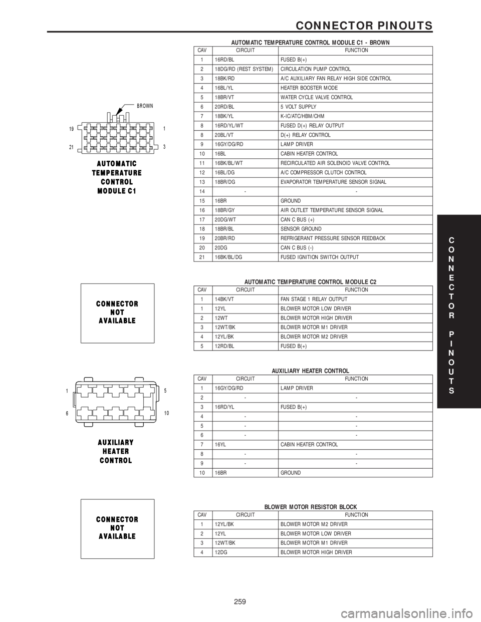
AUTOMATIC TEMPERATURE CONTROL MODULE C1 - BROWNCAV CIRCUIT FUNCTION
1 16RD/BL FUSED B(+)
2 18DG/RD (REST SYSTEM) CIRCULATION PUMP CONTROL
3 18BK/RD A/C AUXILIARY FAN RELAY HIGH SIDE CONTROL
4 16BL/YL HEATER BOOSTER MODE
5 18BR/VT WATER CYCLE VALVE CONTROL
6 20RD/BL 5 VOLT SUPPLY
7 18BK/YL K-IC/ATC/HBM/CHM
8 16RD/YL/WT FUSED D(+) RELAY OUTPUT
8 20BL/VT D(+) RELAY CONTROL
9 16GY/DG/RD LAMP DRIVER
10 16BL CABIN HEATER CONTROL
11 16BK/BL/WT RECIRCULATED AIR SOLENOID VALVE CONTROL
12 16BL/DG A/C COMPRESSOR CLUTCH CONTROL
13 18BR/DG EVAPORATOR TEMPERATURE SENSOR SIGNAL
14 - -
15 16BR GROUND
16 18BR/GY AIR OUTLET TEMPERATURE SENSOR SIGNAL
17 20DG/WT CAN C BUS (+)
18 18BR/BL SENSOR GROUND
19 20BR/RD REFRIGERANT PRESSURE SENSOR FEEDBACK
20 20DG CAN C BUS (-)
21 16BK/BL/DG FUSED IGNITION SWITCH OUTPUT
AUTOMATIC TEMPERATURE CONTROL MODULE C2CAV CIRCUIT FUNCTION
1 14BK/VT FAN STAGE 1 RELAY OUTPUT
1 12YL BLOWER MOTOR LOW DRIVER
2 12WT BLOWER MOTOR HIGH DRIVER
3 12WT/BK BLOWER MOTOR M1 DRIVER
4 12YL/BK BLOWER MOTOR M2 DRIVER
5 12RD/BL FUSED B(+)
AUXILIARY HEATER CONTROLCAV CIRCUIT FUNCTION
1 16GY/DG/RD LAMP DRIVER
2- -
3 16RD/YL FUSED B(+)
4- -
5- -
6- -
7 16YL CABIN HEATER CONTROL
8- -
9- -
10 16BR GROUND
BLOWER MOTOR RESISTOR BLOCKCAV CIRCUIT FUNCTION
1 12YL/BK BLOWER MOTOR M2 DRIVER
2 12YL BLOWER MOTOR LOW DRIVER
3 12WT/BK BLOWER MOTOR M1 DRIVER
4 12DG BLOWER MOTOR HIGH DRIVER
C
O
N
N
E
C
T
O
R
P
I
N
O
U
T
S
259
CONNECTOR PINOUTS
Page 428 of 2305
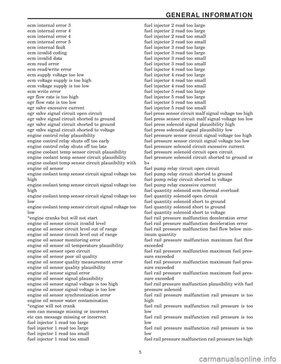
ecm internal error 3
ecm internal error 4
ecm internal error 4
ecm internal error 5
ecm internal fault
ecm invalid coding
ecm invalid data
ecm read error
ecm read/write error
ecm supply voltage too low
ecm voltage supply is too high
ecm voltage supply is too low
ecm write error
egr flow rate is too high
egr flow rate is too low
egr valve excessive current
egr valve signal circuit open circuit
egr valve signal circuit shorted to ground
egr valve signal circuit shorted to ground
egr valve signal circuit shorted to voltage
engine control relay plausibility
engine control relay shuts off too early
engine control relay shuts off too late
engine coolant temp sensor circuit plausibility
engine coolant temp sensor circuit plausibility
engine coolant temp sensor circuit plausibility with
engine oil sensor
engine coolant temp sensor circuit signal voltage too
high
engine coolant temp sensor circuit signal voltage too
high
engine coolant temp sensor circuit signal voltage too
low
engine coolant temp sensor circuit signal voltage too
low
*engine cranks but will not start
engine oil sensor circuit invalid level
engine oil sensor circuit level out of range
engine oil sensor circuit level out of range
engine oil sensor monitoring error
engine oil sensor oil temperature plausibility
engine oil sensor open circuit
engine oil sensor poor oil quality
engine oil sensor quality measurement error
engine oil sensor quality plausibility
engine oil sensor signal error
engine oil sensor signal plausibility
engine oil sensor signal voltage is too high
engine oil sensor signal voltage is too low
engine oil sensor synchronization error
engine oil sensor water contamination
*engine will not crank
esm can message missing or incorrect
etc can message missing or incorrect
fuel injector 1 read too large
fuel injector 1 read too large
fuel injector 1 read too small
fuel injector 1 read too smallfuel injector 2 read too large
fuel injector 2 read too large
fuel injector 2 read too small
fuel injector 2 read too small
fuel injector 3 read too large
fuel injector 3 read too large
fuel injector 3 read too small
fuel injector 3 read too small
fuel injector 4 read too large
fuel injector 4 read too large
fuel injector 4 read too small
fuel injector 4 read too small
fuel injector 5 read too large
fuel injector 5 read too large
fuel injector 5 read too small
fuel injector 5 read too small
fuel press sensor circuit malf signal voltage too high
fuel press sensor circuit malf signal voltage too low
fuel press solenoid signal plausibility high
fuel press solenoid signal plausibility low
fuel pressure sensor circuit signal voltage too high
fuel pressure sensor circuit signal voltage too low
fuel pressure solenoid circuit excessive current
fuel pressure solenoid circuit open circuit
fuel pressure solenoid circuit shorted to ground or
b+
fuel pump relay circuit open circuit
fuel pump relay circuit shorted to ground
fuel pump relay circuit shorted to voltage
fuel pump relay excessive current
fuel quantity solenoid ecm thermal overload
fuel quantity solenoid open circuit
fuel quantity solenoid short to ground
fuel quantity solenoid short to ground
fuel quantity solenoid short to voltage
fuel rail pressure malfunction deceleration error
fuel rail pressure malfunction deceleration error
fuel rail pressure malfunction fuel flow below min-
imum quantity
fuel rail pressure malfunction maximum fuel flow
exceeded
fuel rail pressure malfunction maximum fuel pres-
sure exceeded
fuel rail pressure malfunction maximum fuel pres-
sure exceeded
fuel rail pressure malfunction maximum fuel pres-
sure exceeded
fuel rail pressure malfunction plausibility with fuel
pressure solenoid
fuel rail pressure malfunction rail pressure is too
high
fuel rail pressure malfunction rail pressure is too
low
fuel rail pressure malfunction rail pressure is too
low
fuel rail pressure malfunction rail pressure is too
low
fuel rail pressure malfunction rail pressure too high
5
GENERAL INFORMATION
Page 682 of 2305
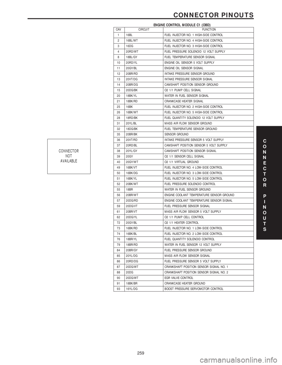
ENGINE CONTROL MODULE C1 (OBD)CAV CIRCUIT FUNCTION
1 16BL FUEL INJECTOR NO. 1 HIGH-SIDE CONTROL
2 16BL/WT FUEL INJECTOR NO. 4 HIGH-SIDE CONTROL
3 16DG FUEL INJECTOR NO. 3 HIGH-SIDE CONTROL
4 20RD/WT FUEL PRESSURE SOLENOID 12 VOLT SUPPLY
8 18BL/GY FUEL TEMPERATURE SENSOR SIGNAL
10 20RD/YL ENGINE OIL SENSOR 5 VOLT SUPPLY
11 20GY/BL ENGINE OIL SENSOR SIGNAL
12 20BR/RD INTAKE PRESSURE SENSOR GROUND
13 20VT/DG INTAKE PRESSURE SENSOR SIGNAL
14 20BR/DG CAMSHAFT POSITION SENSOR GROUND
15 20DG/BK O2 1/1 PUMP CELL SIGNAL
20 18BK/YL WATER IN FUEL SENSOR SIGNAL
21 18BK/RD CRANKCASE HEATER SIGNAL
25 16BK FUEL INJECTOR NO. 2 HIGH-SIDE CONTROL
26 16BK/WT FUEL INJECTOR NO. 5 HIGH-SIDE CONTROL
28 18RD/BK FUEL QUANTITY SOLENOID 12 VOLT SUPPLY
31 20YL/BL MASS AIR FLOW SENSOR GROUND
32 18DG/BK FUEL TEMPERATURE SENSOR GROUND
35 20BR/BK SENSOR GROUND
36 20VT/RD INTAKE PRESSURE SENSOR 5 VOLT SUPPLY
37 20RD/BL CAMSHAFT POSITION SENSOR 5 VOLT SUPPLY
38 20YL/GY CAMSHAFT POSITION SENSOR SIGNAL
39 20GY O2 1/1 SENSOR CELL SIGNAL
40 20GY/WT O2 1/1 VIRTUAL GROUND
49 16BK/VT FUEL INJECTOR NO. 4 LOW-SIDE CONTROL
50 16BK/DG FUEL INJECTOR NO. 3 LOW-SIDE CONTROL
51 16BK/YL FUEL INJECTOR NO. 5 LOW-SIDE CONTROL
52 20BK/WT FUEL PRESSURE SOLENOID CONTROL
55 18BR WATER IN FUEL SENSOR GROUND
56 20BR/WT ENGINE COOLANT TEMPERATURE SENSOR GROUND
57 20DG/RD ENGINE COOLANT TEMPERATURE SENSOR SIGNAL
59 20DG/VT FUEL PRESSURE SENSOR SIGNAL
61 20BR/VT MASS AIR FLOW SENSOR 5 VOLT SUPPLY
62 20DG/YL O2 1/1 PUMP CELL CONTROL
72 20GY/BL O2 1/1 HEATER CONTROL
73 16BK/RD FUEL INJECTOR NO. 1 LOW-SIDE CONTROL
74 16BK/BL FUEL INJECTOR NO. 2 LOW-SIDE CONTROL
76 18BR/YL FUEL QUANTITY SOLENOID CONTROL
79 18BR/RD WATER IN FUEL SENSOR 12 VOLT SUPPLY
84 20BR/GY FUEL PRESSURE SENSOR GROUND
85 20YL/DG MASS AIR FLOW SENSOR SIGNAL
86 20RD/DG FUEL PRESSURE SENSOR 5 VOLT SUPPLY
87 20DG/WT CRANKSHAFT POSITION SENSOR SIGNAL NO. 1
88 20DG CRANKSHAFT POSITION SENSOR SIGNAL NO. 2
90 20DG/WT EGR VALVE CONTROL
91 18BK/BR CRANKCASE HEATER GROUND
93 16YL/DG BOOST PRESSURE SERVOMOTOR CONTROL
C
O
N
N
E
C
T
O
R
P
I
N
O
U
T
S
259
CONNECTOR PINOUTS
Page 717 of 2305
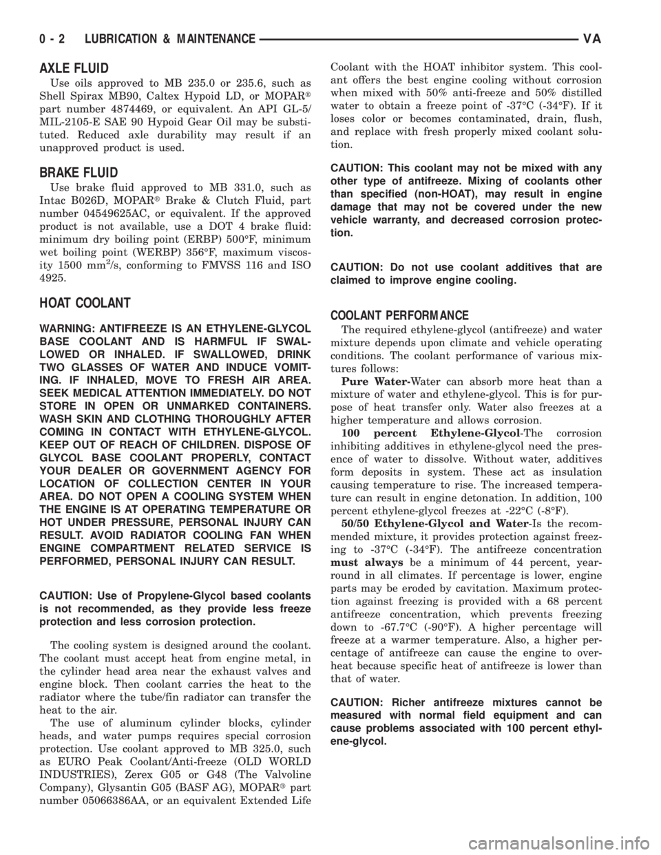
AXLE FLUID
Use oils approved to MB 235.0 or 235.6, such as
Shell Spirax MB90, Caltex Hypoid LD, or MOPARt
part number 4874469, or equivalent. An API GL-5/
MIL-2105-E SAE 90 Hypoid Gear Oil may be substi-
tuted. Reduced axle durability may result if an
unapproved product is used.
BRAKE FLUID
Use brake fluid approved to MB 331.0, such as
Intac B026D, MOPARtBrake & Clutch Fluid, part
number 04549625AC, or equivalent. If the approved
product is not available, use a DOT 4 brake fluid:
minimum dry boiling point (ERBP) 500ÉF, minimum
wet boiling point (WERBP) 356ÉF, maximum viscos-
ity 1500 mm
2/s, conforming to FMVSS 116 and ISO
4925.
HOAT COOLANT
WARNING: ANTIFREEZE IS AN ETHYLENE-GLYCOL
BASE COOLANT AND IS HARMFUL IF SWAL-
LOWED OR INHALED. IF SWALLOWED, DRINK
TWO GLASSES OF WATER AND INDUCE VOMIT-
ING. IF INHALED, MOVE TO FRESH AIR AREA.
SEEK MEDICAL ATTENTION IMMEDIATELY. DO NOT
STORE IN OPEN OR UNMARKED CONTAINERS.
WASH SKIN AND CLOTHING THOROUGHLY AFTER
COMING IN CONTACT WITH ETHYLENE-GLYCOL.
KEEP OUT OF REACH OF CHILDREN. DISPOSE OF
GLYCOL BASE COOLANT PROPERLY, CONTACT
YOUR DEALER OR GOVERNMENT AGENCY FOR
LOCATION OF COLLECTION CENTER IN YOUR
AREA. DO NOT OPEN A COOLING SYSTEM WHEN
THE ENGINE IS AT OPERATING TEMPERATURE OR
HOT UNDER PRESSURE, PERSONAL INJURY CAN
RESULT. AVOID RADIATOR COOLING FAN WHEN
ENGINE COMPARTMENT RELATED SERVICE IS
PERFORMED, PERSONAL INJURY CAN RESULT.
CAUTION: Use of Propylene-Glycol based coolants
is not recommended, as they provide less freeze
protection and less corrosion protection.
The cooling system is designed around the coolant.
The coolant must accept heat from engine metal, in
the cylinder head area near the exhaust valves and
engine block. Then coolant carries the heat to the
radiator where the tube/fin radiator can transfer the
heat to the air.
The use of aluminum cylinder blocks, cylinder
heads, and water pumps requires special corrosion
protection. Use coolant approved to MB 325.0, such
as EURO Peak Coolant/Anti-freeze (OLD WORLD
INDUSTRIES), Zerex G05 or G48 (The Valvoline
Company), Glysantin G05 (BASF AG), MOPARtpart
number 05066386AA, or an equivalent Extended LifeCoolant with the HOAT inhibitor system. This cool-
ant offers the best engine cooling without corrosion
when mixed with 50% anti-freeze and 50% distilled
water to obtain a freeze point of -37ÉC (-34ÉF). If it
loses color or becomes contaminated, drain, flush,
and replace with fresh properly mixed coolant solu-
tion.
CAUTION: This coolant may not be mixed with any
other type of antifreeze. Mixing of coolants other
than specified (non-HOAT), may result in engine
damage that may not be covered under the new
vehicle warranty, and decreased corrosion protec-
tion.
CAUTION: Do not use coolant additives that are
claimed to improve engine cooling.
COOLANT PERFORMANCE
The required ethylene-glycol (antifreeze) and water
mixture depends upon climate and vehicle operating
conditions. The coolant performance of various mix-
tures follows:
Pure Water-Water can absorb more heat than a
mixture of water and ethylene-glycol. This is for pur-
pose of heat transfer only. Water also freezes at a
higher temperature and allows corrosion.
100 percent Ethylene-Glycol-The corrosion
inhibiting additives in ethylene-glycol need the pres-
ence of water to dissolve. Without water, additives
form deposits in system. These act as insulation
causing temperature to rise. The increased tempera-
ture can result in engine detonation. In addition, 100
percent ethylene-glycol freezes at -22ÉC (-8ÉF).
50/50 Ethylene-Glycol and Water-Is the recom-
mended mixture, it provides protection against freez-
ing to -37ÉC (-34ÉF). The antifreeze concentration
must alwaysbe a minimum of 44 percent, year-
round in all climates. If percentage is lower, engine
parts may be eroded by cavitation. Maximum protec-
tion against freezing is provided with a 68 percent
antifreeze concentration, which prevents freezing
down to -67.7ÉC (-90ÉF). A higher percentage will
freeze at a warmer temperature. Also, a higher per-
centage of antifreeze can cause the engine to over-
heat because specific heat of antifreeze is lower than
that of water.
CAUTION: Richer antifreeze mixtures cannot be
measured with normal field equipment and can
cause problems associated with 100 percent ethyl-
ene-glycol.
0 - 2 LUBRICATION & MAINTENANCEVA
Page 792 of 2305
(3) During road test, make normal and firm brake
stops in 25-40 mph range. Note faulty brake opera-
tion such as low pedal, hard pedal, fade, pedal pulsa-
tion, pull, grab, drag, noise, etc.
(4) Attempt to stop the vehicle with the parking
brake only and note grab, drag, noise, etc.
PEDAL FALLS AWAY
A brake pedal that falls away under steady foot
pressure is generally the result of a system leak. The
leak point could be at a brake line, fitting, hose, or
caliper/wheel cylinder. If leakage is severe, fluid will
be evident at or around the leaking component.
Internal leakage (seal by-pass) in the master cylin-
der caused by worn or damaged piston cups, may
also be the problem cause.
An internal leak in the ABS or RWAL system may
also be the problem with no physical evidence.
LOW PEDAL
If a low pedal is experienced, pump the pedal sev-
eral times. If the pedal comes back up worn linings,
rotors, drums, or rear brakes out of adjustment are
the most likely causes. The proper course of action is
to inspect and replace all worn component and make
the proper adjustments.
SPONGY PEDAL
A spongy pedal is most often caused by air in the
system. However, thin brake drums or substandard
brake lines and hoses can also cause a spongy pedal.
The proper course of action is to bleed the system,
and replace thin drums and substandard quality
brake hoses if suspected.
HARD PEDAL OR HIGH PEDAL EFFORT
A hard pedal or high pedal effort may be due to
lining that is water soaked, contaminated, glazed, or
badly worn. The power booster or check valve could
also be faulty.
PEDAL PULSATION
Pedal pulsation is caused by components that are
loose, or beyond tolerance limits.
The primary cause of pulsation are disc brake
rotors with excessive lateral runout or thickness vari-
ation, or out of round brake drums. Other causes are
loose wheel bearings or calipers and worn, damaged
tires.
NOTE: Some pedal pulsation may be felt during
ABS activation.
BRAKE DRAG
Brake drag occurs when the lining is in constant
contact with the rotor or drum. Drag can occur at one
wheel, all wheels, fronts only, or rears only.Drag is a product of incomplete brake shoe release.
Drag can be minor or severe enough to overheat the
linings, rotors and drums.
Minor drag will usually cause slight surface char-
ring of the lining. It can also generate hard spots in
rotors and drums from the overheat-cool down pro-
cess. In most cases, the rotors, drums, wheels and
tires are quite warm to the touch after the vehicle is
stopped.
Severe drag can char the brake lining all the way
through. It can also distort and score rotors and
drums to the point of replacement. The wheels, tires
and brake components will be extremely hot. In
severe cases, the lining may generate smoke as it
chars from overheating.
Common causes of brake drag are:
²Seized or improperly adjusted parking brake
cables.
²Loose/worn wheel bearing.
²Seized caliper or wheel cylinder piston.
²Caliper binding on corroded bushings or rusted
slide surfaces.
²Loose caliper mounting.
²Drum brake shoes binding on worn/damaged
support plates.
²Mis-assembled components.
²Long booster output rod.
If brake drag occurs at all wheels, the problem
may be related to a blocked master cylinder return
port, or faulty power booster (binds-does not release).
BRAKE FADE
Brake fade is usually a product of overheating
caused by brake drag. However, brake overheating
and resulting fade can also be caused by riding the
brake pedal, making repeated high deceleration stops
in a short time span, or constant braking on steep
mountain roads. Refer to the Brake Drag information
in this section for causes.
BRAKE PULL
Front brake pull condition could result from:
²Contaminated lining in one caliper
²Seized caliper piston
²Binding caliper
²Loose caliper
²Rusty caliper slide surfaces
²Improper brake pads
²Damaged rotor
A worn, damaged wheel bearing or suspension
component are further causes of pull. A damaged
front tire (bruised, ply separation) can also cause
pull.
A common and frequently misdiagnosed pull condi-
tion is where direction of pull changes after a few
stops. The cause is a combination of brake drag fol-
lowed by fade at one of the brake units.
VABRAKES - BASE 5 - 3
Page 817 of 2305
CLEANING - REAR DRUM IN HAT BRAKE
Clean the individual brake components, including
the support plate exterior, with a water dampened
cloth or with brake cleaner. Do not use any other
cleaning agents. Remove light rust and scale from
the brake shoe contact pads on the support plate
with fine sandpaper.
INSTALLATION
INSTALLATION - (SRW)
NOTE: Preassemble the retracting spring with the
short hook eye from the inside together with the
adjuster wheel at the bottom. Fit the preassembled
park brake shoes on the brake carrier.
(1)Ensure that the cable lock moves easily
before installing shoes.Install the park brake
shoes.
(2) Install the lower retracting spring using special
tool 9280.
(3) Install the hold down springs using special tool
9281.
(4) Install the upper retracting spring using spe-
cial tool 9280.
(5) Install the adjuster.
(6) Install the front park brake cable to the pulley
unit.
(7) Install the disc brake rotor.
(8) Install the rear wheels.
(9) Adjust the parking brakes.(10) Lower the vehicle.
(11) Pump the brake pedal several times to check
the operation of the brakes before moving vehicle.
INSTALLATION - (DRW)
NOTE: Preassemble the retracting spring with the
short hook eye from the inside together with the
adjuster wheel at the bottom. Fit the preassembled
park brake shoes on the brake carrier.
(1)Ensure that the cable lock moves easily
before installing shoes.Install the park brake
shoes.
(2) Install the lower retracting spring.
(3) Install the pressure hold down springs by
depressing with your fingers and twisting to lock in
place.
(4) Install the upper retracting spring.
(5) Install the adjuster.
(6) Install the front park brake cable to the pulley
unit.
(7) Install the disc brake rotor.
(8) Install the rear wheel flange ring. Tighten to
200 N´m (148 ft. lbs.).
(9) Install the rear wheels.
(10) Adjust the parking brakes.
(11) Lower the vehicle.
(12) Pump the brake pedal several times to check
the operation of the brakes before moving vehicle.
ADJUSTMENTS
ADJUSTMENT
(1) Raise and support the vehicle.
(2) Remove the rear wheels.
(3) Turn the adjusting wheel through the hole of
the wheel lug bolt until it is no longer possible to
rotate the rear wheel (Fig. 38).
(4) Loosen the adjusting wheel 3-4 teeth divisions
(Fig. 38).
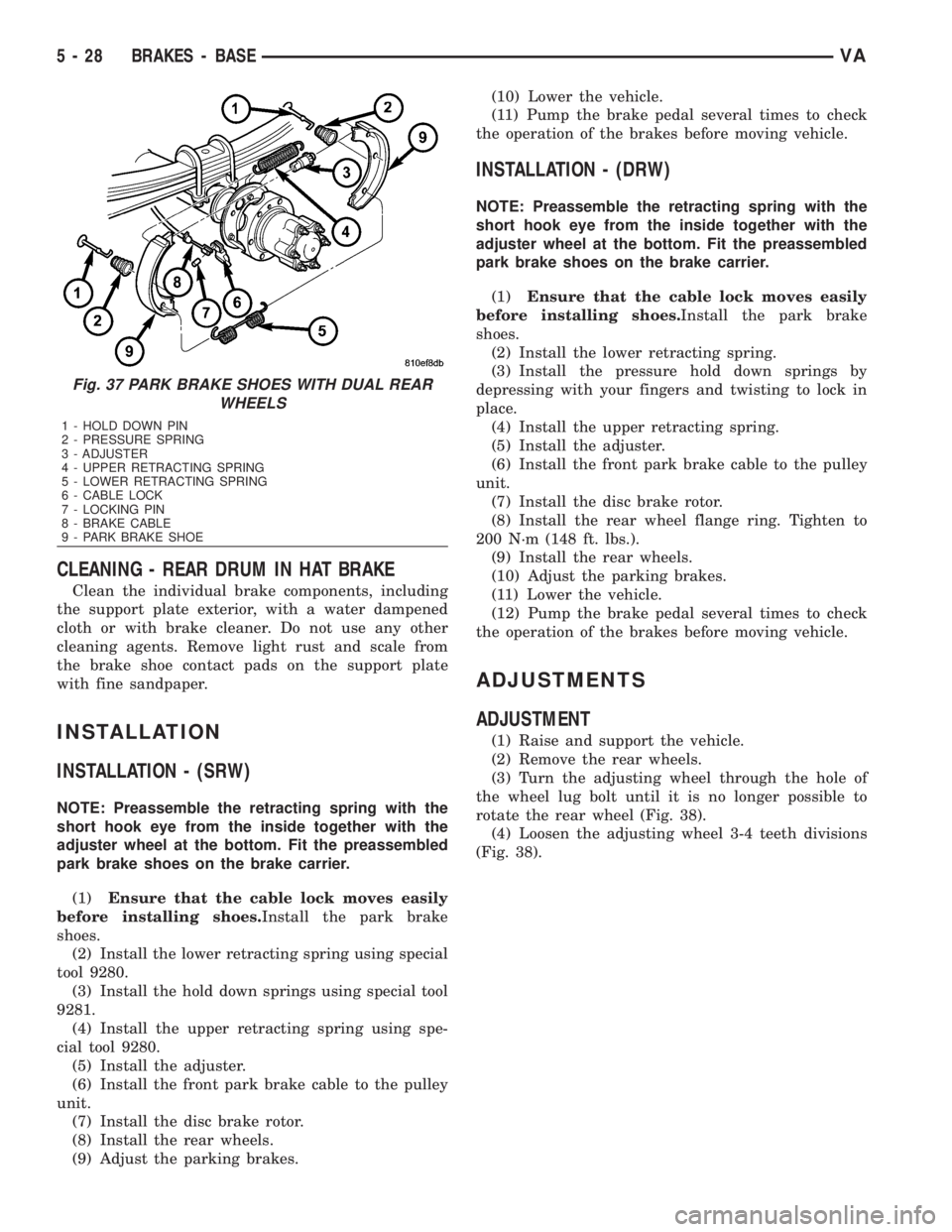
Fig. 37 PARK BRAKE SHOES WITH DUAL REAR
WHEELS
1 - HOLD DOWN PIN
2 - PRESSURE SPRING
3 - ADJUSTER
4 - UPPER RETRACTING SPRING
5 - LOWER RETRACTING SPRING
6 - CABLE LOCK
7 - LOCKING PIN
8 - BRAKE CABLE
9 - PARK BRAKE SHOE
5 - 28 BRAKES - BASEVA