set clock MERCEDES-BENZ SPRINTER 2006 User Guide
[x] Cancel search | Manufacturer: MERCEDES-BENZ, Model Year: 2006, Model line: SPRINTER, Model: MERCEDES-BENZ SPRINTER 2006Pages: 2305, PDF Size: 48.12 MB
Page 940 of 2305
next required engine oil maintenance is anticipated.
ASSYST also provides several audible indications
using the electronic tone generator on the instrument
cluster circuit board to supplement these visual dis-
plays.
The indications of the ASSYST engine oil mainte-
nance indicator are not visible when the LCD is not
illuminated. When illuminated, the ASSYST indica-
tions appear as dark characters and icons silhouetted
against an amber field. When the exterior lighting is
turned Off, the display is illuminated at maximum
brightness. When the exterior lighting is turned On,
the display illumination level can be adjusted in con-
cert with the cluster general illumination lighting
using the ª+º (plus) and ª2º (minus) multi-function
indicator push buttons. The ASSYST engine oil main-
tenance indicator is serviced as a unit with the
instrument cluster.
OPERATION
The ASSYST engine oil maintenance indicator
microprocessor uses numerous criteria besides time
and mileage to evaluate vehicle maintenance require-
ments. Time data is taken from the electronic digital
clock integral to the instrument cluster. Vehicle dis-
tance data is obtained from the Controller Antilock
Brake (CAB) over the Controller Area Network
(CAN) data bus. Coolant temperature, engine oil
temperature, engine oil level, engine oil quality,
engine speed, and engine load data are obtained from
the Engine Control Module (ECM) over the CAN
data bus. Using all of the available data and internal
programming, the ASSYST microprocessor then cal-
culates the estimated time and distance to the next
required engine oil maintenance interval. The
ASSYST uses the multi-function indicator LCD to
display that data and, when necessary, issues audible
alerts to the vehicle operator through the electronic
tone generator on the cluster circuit board.
See the owner's manual in the vehicle glove box for
more information on the features, use, operation and
resetting procedures for the ASSYST maintenance
computer. Proper diagnosis and testing of the
ASSYST engine oil maintenance computer, the CAN
data bus and the electronic data bus message inputs
to the EMIC that are used by the ASSYST computer
for its calculations requires the use of a diagnostic
scan tool. Refer to the appropriate diagnostic infor-
mation.
MALFUNCTION INDICATOR
LAMP (MIL)
DESCRIPTION
A Malfunction Indicator Lamp (MIL) is standard
equipment on all instrument clusters. The MIL islocated near the lower edge of the instrument cluster,
to the right of the multi-function indicator display.
The MIL consists of the International Control and
Display Symbol icon for ªEngineº imprinted within a
rectangular cutout in the opaque layer of the instru-
ment cluster overlay. The dark outer layer of the
overlay prevents the indicator from being clearly vis-
ible when it is not illuminated. An amber Light
Emitting Diode (LED) behind the cutout in the
opaque layer of the overlay causes the icon to appear
silhouetted against an amber field through the trans-
lucent outer layer of the overlay when the indicator
is illuminated from behind by the LED, which is sol-
dered onto the instrument cluster electronic circuit
board. The MIL is serviced as a unit with the instru-
ment cluster.
OPERATION
The Malfunction Indicator Lamp (MIL) gives an
indication to the vehicle operator when the Engine
Control Module (ECM) has recorded a Diagnostic
Trouble Code (DTC) for an On-Board Diagnostics II
(OBDII) emissions-related circuit or component mal-
function. The MIL is controlled by a transistor on the
instrument cluster circuit board based upon cluster
programming and electronic messages received by
the cluster from the ECM over the Controller Area
Network (CAN) data bus. The MIL Light Emitting
Diode (LED) is completely controlled by the instru-
ment cluster logic circuit, and that logic will only
allow this indicator to operate when the instrument
cluster detects that the ignition switch is in the On
position. Therefore, the LED will always be off when
the ignition switch is in any position except On. The
LED only illuminates when it is provided a path to
ground by the instrument cluster transistor. The
instrument cluster will turn on the MIL for the fol-
lowing reasons:
²Bulb Test- Each time the ignition switch is
turned to the On position the MIL is illuminated as a
bulb test. The indicator will remain illuminated until
the engine is started, or until the ignition switch is
turned to the Off position, whichever occurs first.
²MIL Lamp-On Message- Each time the clus-
ter receives a MIL lamp-on message from the ECM,
the indicator will be illuminated. The indicator will
remain illuminated until the detected fault is
repaired, or until the ignition switch is turned to the
Off position, whichever occurs first. For more infor-
mation on the ECM and the DTC set and reset
parameters, (Refer to 25 - EMISSIONS CONTROL -
OPERATION).
²Communication Error- If the cluster receives
no lamp-on or lamp-off message from the ECM, the
MIL is illuminated by the instrument cluster. The
indicator remains controlled and illuminated by the
cluster until a valid lamp-on or lamp-off message is
received from the ECM.
VAINSTRUMENT CLUSTER 8J - 21
Page 941 of 2305
The ECM continually monitors the fuel and emis-
sions system circuits and sensors to decide whether
the system is in good operating condition. The ECM
then sends the proper lamp-on or lamp-off messages
to the instrument cluster. If the instrument cluster
turns on the MIL after the bulb test, it may indicate
that a malfunction has occurred and that the fuel
and emissions systems may require service. For
proper diagnosis of the fuel and emissions systems,
the ECM, the CAN data bus, or the electronic mes-
sage inputs to the instrument cluster that control the
MIL, a diagnostic scan tool is required. Refer to the
appropriate diagnostic information.
MULTI - FUNCTION INDICA-
TOR
DESCRIPTION
A multi-function indicator is standard equipment
on all instrument clusters. The multi-function indica-
tor is located near the lower edge of the instrument
cluster, directly below the speedometer. The multi-
function indicator consists of a Liquid Crystal Dis-
play (LCD) unit and four push button-controlled
switches that are soldered onto the instrument clus-
ter electronic circuit board. The LCD is visible
through a large rectangular cutout in the instrument
cluster overlay, while the four switch push buttons
extend through a black plastic switch bezel located
on the cluster lens directly below the LCD. The four
multi-function indicator push buttons allow the vehi-
cle operator to configure and adjust several of the
display features. The buttons are labeled from left to
right: ªmiº (miles) or ªkmº (kilometers), an icon
depicting an analog clock face (clock), ª2º (minus),
and ª+º (plus).
The multi-function indicator LCD displays both
alpha-numeric characters and numerous icons to pro-
vide information to the vehicle operator. The indica-
tions of the multi-function indicator are not visible
when the LCD is not illuminated. When illuminated
the indications appear as dark characters and icons
silhouetted against an amber field. When the exterior
lighting is turned Off, the display is illuminated at
maximum brightness. When the exterior lighting is
turned On the display illumination level can be
adjusted in concert with the cluster general illumina-
tion lighting using the ª+º (plus) and ª2º (minus)
multi-function indicator push buttons. The multi-
function indicator LCD unit and push button
switches are serviced as a unit with the instrument
cluster.
OPERATION
The multi-function indicator has several display
capabilities including odometer, trip odometer, clock,engine oil level data, gear selector indicator
(PRNDL), certain diagnostic information and, on
vehicles so equipped, an optional Active Service SYS-
Tem (ASSYST) engine oil maintenance indicator and
an optional outside ambient temperature indicator.
The multi-function indicator is completely controlled
by the instrument cluster logic circuit, and that logic
will allow this indication to be viewed whenever the
multi-function indicator Liquid Crystal Display
(LCD) is activated. Therefore, the indicator remains
functional regardless of the ignition switch position.
With the ignition switch in the Off or Accessory posi-
tions and the key removed from the ignition lock cyl-
inder, the display is activated when the park lamps
are turned On or, for about thirty seconds after any
one of the multi-function indicator switch push but-
tons is depressed. Otherwise, the display unit is
active for about thirty seconds after the key is
inserted into the ignition lock cylinder, and inactive
about thirty seconds after the key is removed from
the ignition lock cylinder.
The multi-function indicator ªmiº (miles) or
ªkmº(kilometers) switch push button is used to con-
trol the odometer/trip odometer display modes. The
multi-function indicator clock switch push button is
used to control the clock/outside temperature display
modes. The multi-function indicator ª+º (plus) and
ª2º (minus) switch push buttons are used to adjust
the cluster general illumination dimming level, the
clock, and other cluster settings. See the owner's
manual in the vehicle glove box for more information
on the features, use, operation and setting proce-
dures for the various standard and optional multi-
function indicator displays.
Proper testing of the multi-function indicator LCD
unit, the CAN data bus and the electronic data bus
message inputs to the instrument cluster that control
some of the multi-function indicator functions
requires the use of a diagnostic scan tool. Refer to
the appropriate diagnostic information. Additional
details for the odometer/trip odometer, the clock, the
gear selector indicator, the ambient temperature indi-
cator and the ASSYST warning and reminder func-
tions of the multi-function indicator may be found
elsewhere in this service information.
ODOMETER
DESCRIPTION
An odometer and trip odometer are standard
equipment in all instrument clusters. The odometer
and trip odometer values are displayed on the left
side of the multi-function indicator Liquid Crystal
Display (LCD). The LCD is soldered onto the cluster
electronic circuit board and is visible through a win-
dow with a clear lens located near the lower edge of
8J - 22 INSTRUMENT CLUSTERVA
Page 1637 of 2305
(6) Remove pressed - out oil pump chain pin from
chain seperation tool.
CAUTION: IT IS ESSENTIAL that the installation pro-
cedure for the oil pump chain is followed exactly.
Failure to do so will result in severe engine dam-
age.
INSTALLATION
INSTALLATION
NOTE: If the oil pump is dry, fill it with clean engine
oil before installation. Clean the oil pick±up tube
and strainer.
(1) Clean all sealing surfaces.
(2) Position the oil pump onto the drive chain and
reset tensioner.
(3) Install oil pump retaining bolts and tighten to
18 N´m (160 lbs. in.).
(4) Install the oil pan (Refer to 9 - ENGINE/LU-
BRICATION/OIL PUMP - INSTALLATION).
(5) Refill the crankcase to the appropriate level
with the proper engine oil (Refer to LUBRICATION
& MAINTENANCE/FLUID TYPES - SPECIFICA-
TIONS).
WARNING: USE EXTREME CAUTION WHEN THE
ENGINE IS OPERATING. DO NOT PUT YOUR
HANDS NEAR THE PULLEYS, BELTS OR FAN. DO
NOT WEAR LOOSE CLOTHES.
(6) Start the vehicle and inspect for leaks.
INSTALLATION - OIL PUMP CHAIN
CAUTION: IT IS ESSENTIAL that the installation pro-
cedure is followed exactly. Failure to do so will
result in severe engine damage.
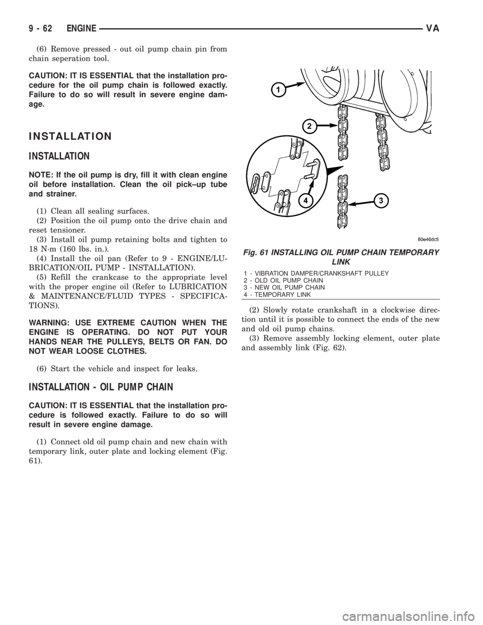
(1) Connect old oil pump chain and new chain with
temporary link, outer plate and locking element (Fig.
61).(2) Slowly rotate crankshaft in a clockwise direc-
tion until it is possible to connect the ends of the new
and old oil pump chains.
(3) Remove assembly locking element, outer plate
and assembly link (Fig. 62).
Fig. 61 INSTALLING OIL PUMP CHAIN TEMPORARY
LINK
1 - VIBRATION DAMPER/CRANKSHAFT PULLEY
2 - OLD OIL PUMP CHAIN
3 - NEW OIL PUMP CHAIN
4 - TEMPORARY LINK
9 - 62 ENGINEVA
Page 1878 of 2305
(14) Remove the transmission oil filter (1) and
o-ring from the electrohydraulic control unit.
(15) Clean the inside of the oil pan (3) of any
debris. Inspect the oil pan gasket (2) and replace if
necessary.
(16) Install a new oil filter (1) and o-ring into the
electrohydraulic control unit.
(17) Install the oil pan (3) and gasket (2) onto the
transmission.
(18) Install the oil pan bolts (5) and retainers (4).
Torque the bolts to 8 N´m (70 in.lbs.).
(19) Lower the vehicle and add 7.0 L (7.4 qts.) of
transmission fluid to the transmission.
(20) Check the oil level (Refer to 21 - TRANSMIS-
SION/AUTOMATIC - NAG1/FLUID AND FILTER -
STANDARD PROCEDURE - CHECK OIL LEVEL).
FREEWHEELING CLUTCH
DESCRIPTION
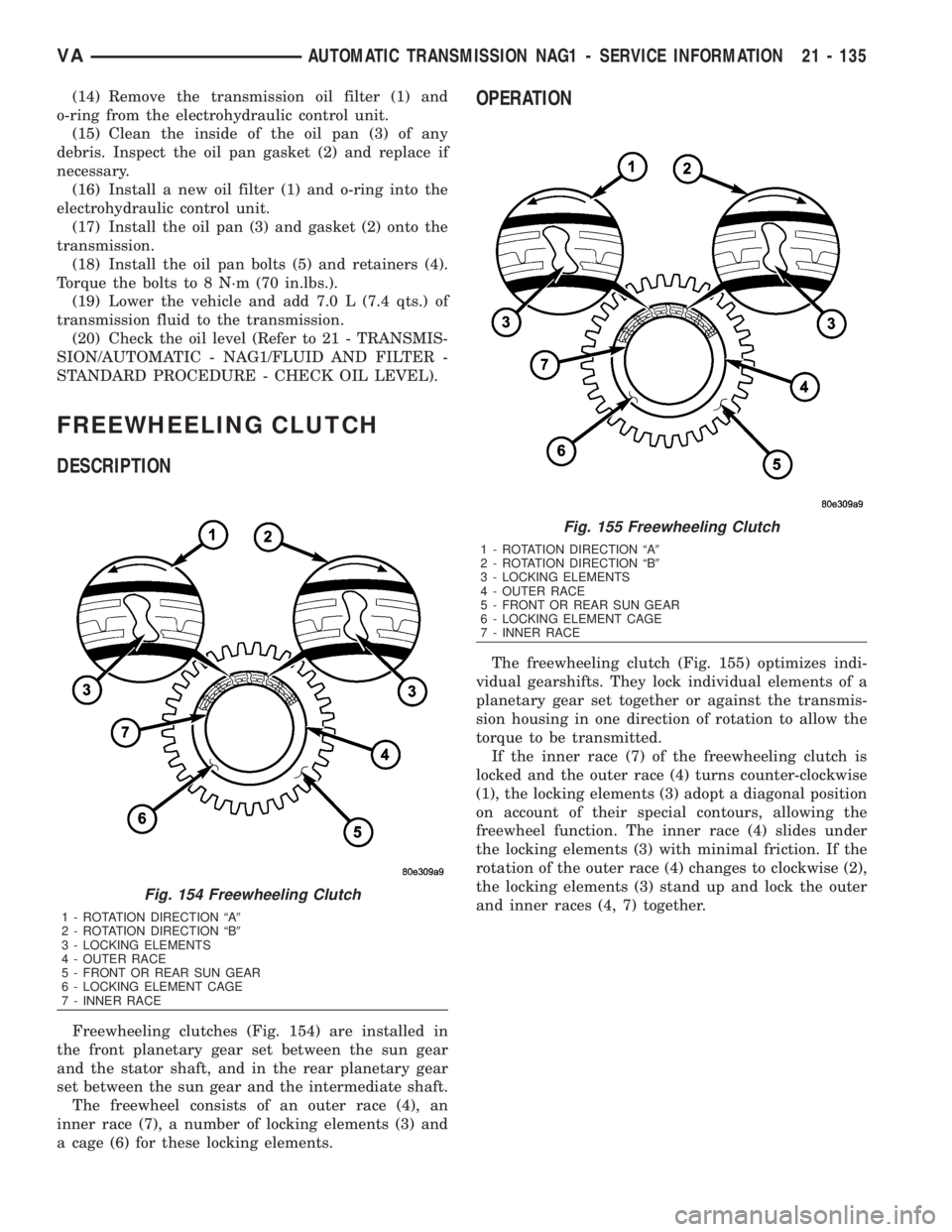
Freewheeling clutches (Fig. 154) are installed in
the front planetary gear set between the sun gear
and the stator shaft, and in the rear planetary gear
set between the sun gear and the intermediate shaft.
The freewheel consists of an outer race (4), an
inner race (7), a number of locking elements (3) and
a cage (6) for these locking elements.
OPERATION
The freewheeling clutch (Fig. 155) optimizes indi-
vidual gearshifts. They lock individual elements of a
planetary gear set together or against the transmis-
sion housing in one direction of rotation to allow the
torque to be transmitted.
If the inner race (7) of the freewheeling clutch is
locked and the outer race (4) turns counter-clockwise
(1), the locking elements (3) adopt a diagonal position
on account of their special contours, allowing the
freewheel function. The inner race (4) slides under
the locking elements (3) with minimal friction. If the
rotation of the outer race (4) changes to clockwise (2),
the locking elements (3) stand up and lock the outer
and inner races (4, 7) together.
Fig. 154 Freewheeling Clutch
1 - ROTATION DIRECTION ªA9
2 - ROTATION DIRECTION ªB9
3 - LOCKING ELEMENTS
4 - OUTER RACE
5 - FRONT OR REAR SUN GEAR
6 - LOCKING ELEMENT CAGE
7 - INNER RACE
Fig. 155 Freewheeling Clutch
1 - ROTATION DIRECTION ªA9
2 - ROTATION DIRECTION ªB9
3 - LOCKING ELEMENTS
4 - OUTER RACE
5 - FRONT OR REAR SUN GEAR
6 - LOCKING ELEMENT CAGE
7 - INNER RACE
VAAUTOMATIC TRANSMISSION NAG1 - SERVICE INFORMATION 21 - 135
Page 1924 of 2305
STATOR
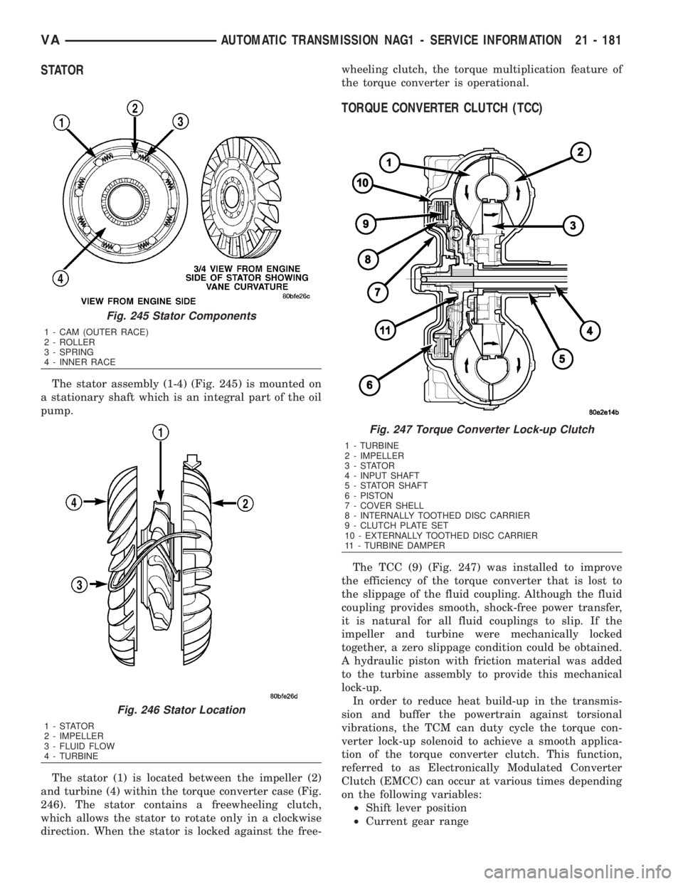
The stator assembly (1-4) (Fig. 245) is mounted on
a stationary shaft which is an integral part of the oil
pump.
The stator (1) is located between the impeller (2)
and turbine (4) within the torque converter case (Fig.
246). The stator contains a freewheeling clutch,
which allows the stator to rotate only in a clockwise
direction. When the stator is locked against the free-wheeling clutch, the torque multiplication feature of
the torque converter is operational.
TORQUE CONVERTER CLUTCH (TCC)
The TCC (9) (Fig. 247) was installed to improve
the efficiency of the torque converter that is lost to
the slippage of the fluid coupling. Although the fluid
coupling provides smooth, shock-free power transfer,
it is natural for all fluid couplings to slip. If the
impeller and turbine were mechanically locked
together, a zero slippage condition could be obtained.
A hydraulic piston with friction material was added
to the turbine assembly to provide this mechanical
lock-up.
In order to reduce heat build-up in the transmis-
sion and buffer the powertrain against torsional
vibrations, the TCM can duty cycle the torque con-
verter lock-up solenoid to achieve a smooth applica-
tion of the torque converter clutch. This function,
referred to as Electronically Modulated Converter
Clutch (EMCC) can occur at various times depending
on the following variables:
²Shift lever position
²Current gear range
Fig. 245 Stator Components
1 - CAM (OUTER RACE)
2 - ROLLER
3 - SPRING
4 - INNER RACE
Fig. 246 Stator Location
1-STATOR
2 - IMPELLER
3 - FLUID FLOW
4 - TURBINE
Fig. 247 Torque Converter Lock-up Clutch
1 - TURBINE
2 - IMPELLER
3-STATOR
4 - INPUT SHAFT
5 - STATOR SHAFT
6 - PISTON
7 - COVER SHELL
8 - INTERNALLY TOOTHED DISC CARRIER
9 - CLUTCH PLATE SET
10 - EXTERNALLY TOOTHED DISC CARRIER
11 - TURBINE DAMPER
VAAUTOMATIC TRANSMISSION NAG1 - SERVICE INFORMATION 21 - 181
Page 2100 of 2305
SYSTEM EMPTY
(1) Evacuate the refrigerant system to the lowest
degree of vacuum possible (approximately 28 in Hg.)
(Refer to 24 - HEATING & AIR CONDITIONING/
PLUMBING - STANDARD PROCEDURE - REFRIG-
ERANT SYSTEM EVACUATE). Determine if the
system holds a vacuum for 15 minutes. If vacuum is
held, a leak is probably not present. If system will
not maintain vacuum level, proceed to Step 2.
(2) Prepare and dispense 0.284 kilograms (10
ounces) of R-134a refrigerant into the evacuated
refrigerant system (Refer to 24 - HEATING & AIR
CONDITIONING/PLUMBING - STANDARD PRO-
CEDURE - REFRIGERANT SYSTEM CHARGE) and
proceed to Step 1 of the System Low procedure.
SYSTEM LOW
(1) Position the vehicle in a wind free work area.
This will aid in detecting small leaks.
(2) Operate the heating-A/C system with the
engine at idle under the following conditions for at
least five minutes.
²Doors or windows open
²Transmission in Park
²A/C-heater controls set to outside air, full cool,
panel mode, high blower and with A/C compressor
engaged
CAUTION: A leak detector only designed for R-12
refrigerant will not detect leaks in a R-134a refriger-
ant system.
(3) Shut the vehicle Off and wait 2-7 minutes.
Then use an electronic leak detector that is designed
to detect R-134a refrigerant and search for leaks. Fit-
tings, lines or components that appear to be oily usu-
ally indicate a refrigerant leak. To inspect the A/C
evaporator for leaks, insert the leak detector probe
into the drain tube opening or an air outlet. A dye for
R-134a is available to aid in leak detection. Use only
DaimlerChrysler approved refrigerant dye.
STANDARD PROCEDURE
REFRIGERANT SYSTEM SERVICE EQUIPMENT
WARNING: Eye protection must be worn when ser-
vicing an A/C refrigerant system. Turn off (rotate
clockwise) all valves on the equipment being used,
before connecting to or disconnecting from the
refrigerant system. Failure to observe these warn-
ings may result in possible personal injury.
WARNING: Refer to the applicable warnings and
cautions for this system before performing the fol-
lowing operation (Refer to 24 - HEATING & AIR
CONDITIONING/PLUMBING - WARNINGS) and (Referto 24 - HEATING & AIR CONDITIONING/PLUMBING -
CAUTIONS). Failure to follow the warnings and cau-
tions could result in possible personal injury or
death.
When servicing the air conditioning system, a
R-134a refrigerant recovery/recycling/charging sta-
tion that meets SAE Standard J2210 must be used.
Contact an automotive service equipment supplier for
refrigerant recovery/recycling/charging equipment.
Refer to the operating instructions supplied by the
equipment manufacturer for proper care and use of
this equipment.
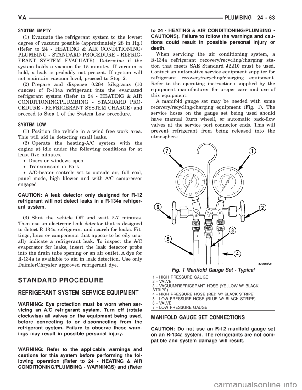
A manifold gauge set may be needed with some
recovery/recycling/charging equipment (Fig. 1). The
service hoses on the gauge set being used should
have manual (turn wheel), or automatic back-flow
valves at the service port connector ends. This will
prevent refrigerant from being released into the
atmosphere.
MANIFOLD GAUGE SET CONNECTIONS
CAUTION: Do not use an R-12 manifold gauge set
on an R-134a system. The refrigerants are not com-
patible and system damage will result.
Fig. 1 Manifold Gauge Set - Typical
1 - HIGH PRESSURE GAUGE
2 - VALVE
3 - VACUUM/REFRIGERANT HOSE (YELLOW W/ BLACK
STRIPE)
4 - HIGH PRESSURE HOSE (RED W/ BLACK STRIPE)
5 - LOW PRESSURE HOSE (BLUE W/ BLACK STRIPE)
6 - VALVE
7 - LOW PRESSURE GAUGE
VAPLUMBING 24 - 63