fan MERCEDES-BENZ SPRINTER 2006 Owner's Manual
[x] Cancel search | Manufacturer: MERCEDES-BENZ, Model Year: 2006, Model line: SPRINTER, Model: MERCEDES-BENZ SPRINTER 2006Pages: 2305, PDF Size: 48.12 MB
Page 298 of 2305
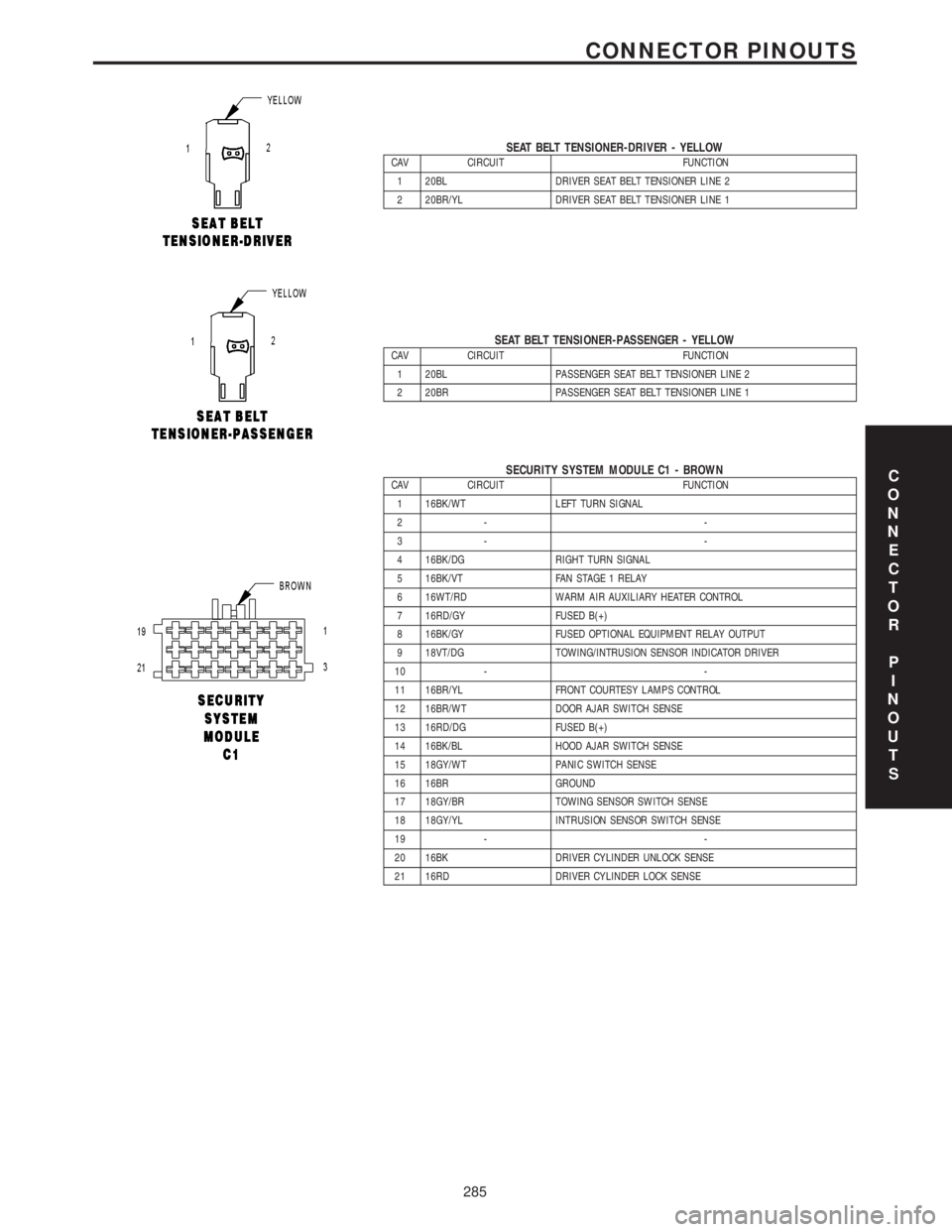
SEAT BELT TENSIONER-DRIVER - YELLOWCAV CIRCUIT FUNCTION
1 20BL DRIVER SEAT BELT TENSIONER LINE 2
2 20BR/YL DRIVER SEAT BELT TENSIONER LINE 1
SEAT BELT TENSIONER-PASSENGER - YELLOWCAV CIRCUIT FUNCTION
1 20BL PASSENGER SEAT BELT TENSIONER LINE 2
2 20BR PASSENGER SEAT BELT TENSIONER LINE 1
SECURITY SYSTEM MODULE C1 - BROWNCAV CIRCUIT FUNCTION
1 16BK/WT LEFT TURN SIGNAL
2- -
3- -
4 16BK/DG RIGHT TURN SIGNAL
5 16BK/VT FAN STAGE 1 RELAY
6 16WT/RD WARM AIR AUXILIARY HEATER CONTROL
7 16RD/GY FUSED B(+)
8 16BK/GY FUSED OPTIONAL EQUIPMENT RELAY OUTPUT
9 18VT/DG TOWING/INTRUSION SENSOR INDICATOR DRIVER
10 - -
11 16BR/YL FRONT COURTESY LAMPS CONTROL
12 16BR/WT DOOR AJAR SWITCH SENSE
13 16RD/DG FUSED B(+)
14 16BK/BL HOOD AJAR SWITCH SENSE
15 18GY/WT PANIC SWITCH SENSE
16 16BR GROUND
17 18GY/BR TOWING SENSOR SWITCH SENSE
18 18GY/YL INTRUSION SENSOR SWITCH SENSE
19 - -
20 16BK DRIVER CYLINDER UNLOCK SENSE
21 16RD DRIVER CYLINDER LOCK SENSEC
O
N
N
E
C
T
O
R
P
I
N
O
U
T
S
285
CONNECTOR PINOUTS
Page 382 of 2305
TEST ACTION APPLICABILITY
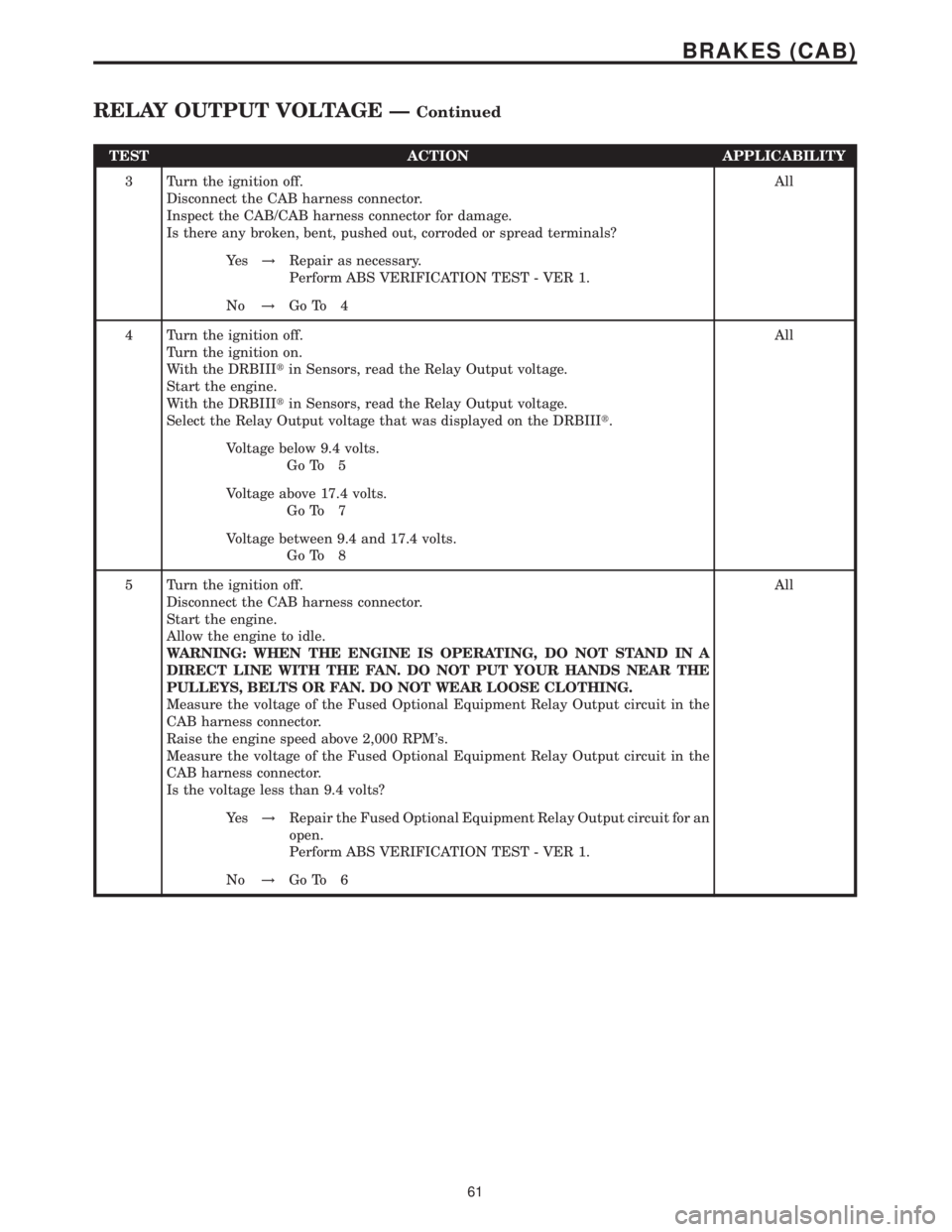
3 Turn the ignition off.
Disconnect the CAB harness connector.
Inspect the CAB/CAB harness connector for damage.
Is there any broken, bent, pushed out, corroded or spread terminals?All
Ye s!Repair as necessary.
Perform ABS VERIFICATION TEST - VER 1.
No!Go To 4
4 Turn the ignition off.
Turn the ignition on.
With the DRBIIItin Sensors, read the Relay Output voltage.
Start the engine.
With the DRBIIItin Sensors, read the Relay Output voltage.
Select the Relay Output voltage that was displayed on the DRBIIIt.All
Voltage below 9.4 volts.
Go To 5
Voltage above 17.4 volts.
Go To 7
Voltage between 9.4 and 17.4 volts.
Go To 8
5 Turn the ignition off.
Disconnect the CAB harness connector.
Start the engine.
Allow the engine to idle.
WARNING: WHEN THE ENGINE IS OPERATING, DO NOT STAND IN A
DIRECT LINE WITH THE FAN. DO NOT PUT YOUR HANDS NEAR THE
PULLEYS, BELTS OR FAN. DO NOT WEAR LOOSE CLOTHING.
Measure the voltage of the Fused Optional Equipment Relay Output circuit in the
CAB harness connector.
Raise the engine speed above 2,000 RPM's.
Measure the voltage of the Fused Optional Equipment Relay Output circuit in the
CAB harness connector.
Is the voltage less than 9.4 volts?All
Ye s!Repair the Fused Optional Equipment Relay Output circuit for an
open.
Perform ABS VERIFICATION TEST - VER 1.
No!Go To 6
61
BRAKES (CAB)
RELAY OUTPUT VOLTAGE ÐContinued
Page 383 of 2305
TEST ACTION APPLICABILITY
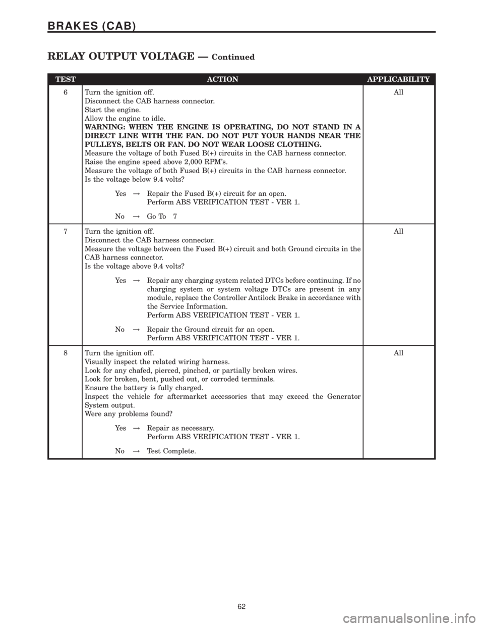
6 Turn the ignition off.
Disconnect the CAB harness connector.
Start the engine.
Allow the engine to idle.
WARNING: WHEN THE ENGINE IS OPERATING, DO NOT STAND IN A
DIRECT LINE WITH THE FAN. DO NOT PUT YOUR HANDS NEAR THE
PULLEYS, BELTS OR FAN. DO NOT WEAR LOOSE CLOTHING.
Measure the voltage of both Fused B(+) circuits in the CAB harness connector.
Raise the engine speed above 2,000 RPM's.
Measure the voltage of both Fused B(+) circuits in the CAB harness connector.
Is the voltage below 9.4 volts?All
Ye s!Repair the Fused B(+) circuit for an open.
Perform ABS VERIFICATION TEST - VER 1.
No!Go To 7
7 Turn the ignition off.
Disconnect the CAB harness connector.
Measure the voltage between the Fused B(+) circuit and both Ground circuits in the
CAB harness connector.
Is the voltage above 9.4 volts?All
Ye s!Repair any charging system related DTCs before continuing. If no
charging system or system voltage DTCs are present in any
module, replace the Controller Antilock Brake in accordance with
the Service Information.
Perform ABS VERIFICATION TEST - VER 1.
No!Repair the Ground circuit for an open.
Perform ABS VERIFICATION TEST - VER 1.
8 Turn the ignition off.
Visually inspect the related wiring harness.
Look for any chafed, pierced, pinched, or partially broken wires.
Look for broken, bent, pushed out, or corroded terminals.
Ensure the battery is fully charged.
Inspect the vehicle for aftermarket accessories that may exceed the Generator
System output.
Were any problems found?All
Ye s!Repair as necessary.
Perform ABS VERIFICATION TEST - VER 1.
No!Test Complete.
62
BRAKES (CAB)
RELAY OUTPUT VOLTAGE ÐContinued
Page 425 of 2305
3.2.2 ECM OPERATING MODES
As input signals to the ECM change, the ECM
adjusts its response to the output devices. For
example, the ECM must calculate a different fuel
quantity and fuel timing for engine idle condition
than it would for a wide open throttle condition.
There are several different modes of operation that
determine how the ECM responds to the various
input signals.
Ignition Switch On (Engine Off)
When the ignition is turned on the ECM activates
the glow plug relay for a time period that is deter-
mined by engine coolant temperature, intake air
temperature and battery voltage.
Engine Start-Up Mode
The ECM uses the intake air temperature sensor,
engine temperature sensor and the crankshaft po-
sition sensor (engine speed) inputs to determine
fuel injection quantity.
Normal Driving Modes
Engine idle, warm-up, acceleration, deceleration
and wide open throttle modes are controlled based
on all of the sensor inputs to the ECM. The ECM
uses these sensor inputs to adjust fuel quantity and
fuel injector timing. EGR valve control is performed
using feedback from the oxygen sensor. An oxygen
sensor is located in the exhaust manifold to sample
oxygen content exiting the engine cylinders. The
ECM uses the O2 sensor, along with other sensor
inputs, to govern the amount of exhaust gas recir-
culation to reduce HC (HydroCarbons) and CO
(Carbon Monoxide). Engine coolant is routed
through the base of the EGR valve to provide
additional cooling of the exhaust gas, which further
helps the reductions of emissions. The EGR valve
has a self-cleaning function. When the engine is
shut off, the EGR valve rotates twice to reduce
carbon deposits at the valve seat.
Overheat Production Mode
If the engine temperature is above 105ÉC (221ÉF)
and vehicle speed is above 40 km/h (25 MPH) the
ECM will limit fuel quantity for engine protection.
Limp-In Mode
The ECM utilizes different degrees of engine
limp-in. The ECM is able to limit engine rpm,
engine power output (turbo boost reduction), acti-
vate engine cooling fan or all of these functions
based on the type of fault that is detected. Critical
engine performance faults such as accelerator pedal
position sensor fault will result in a fixed idle speed
of approximately 680 rpm regardless of actual pedalposition. Other less critical faults will result in
power reduction throughout the full range of driv-
ing conditions.
Overspeed Detection Mode
If the ECM detects engine RPM that exceeds
5200 RPM, the ECM will set a DTC in memory,
limit engine RPM to no more than 2500 RPM, and
illuminate the MIL until the DTC is cleared.
After-Run Mode
The ECM transfers RAM information to ROM
and performs an Input/Output state check.
3.2.3 MONITORED CIRCUITS
The ECM is able to monitor and identify most
driveability related trouble conditions. Some cir-
cuits are directly monitored through ECM feedback
circuitry. In addition, the ECM monitors the voltage
state of some circuits and compares those states
with expected values. Other systems are monitored
indirectly when the ECM conducts a rationality test
to identify problems.
Although most subsystems of the engine control
module are either directly or indirectly monitored,
there may be occasions when diagnostic trouble
codes are not immediately identified. For a trouble
code to set, a specific set of conditions must occur
and unless these conditions occur, a DTC will not
set.
3.2.4 SKREEM OVERVIEW
The sentry key remote entry module system
(SKREEM) is designed to prevent unauthorized
vehicle operation. The system consists of a sentry
key remote entry module (SKREEM), ignition
key(s) equipped with a transponder chip and the
ECM. When the ignition switch is turned on, the
SKREEM interrogates the ignition key. If the igni-
tion key is Valid or Invalid, the SKREEM sends a
message to the ECM indicating ignition key status.
Upon receiving this message the ECM will termi-
nate engine operation or allow the engine to con-
tinue to operate.
3.2.5 SKREEM ON-BOARD DIAGNOSTICS
The SKREEM has been programmed to transmit
and monitor many different coded messages as well
as CAN Bus messages. This monitoring is called
On-Board Diagnostics. Certain criteria must be met
for a DTC to be entered into SKREEM memory. The
criteria may be a range of; input voltage, CAN Bus
message or coded messages to the SKREEM. If all
the criteria for monitoring a circuit or function are
met and a fault is detected, a DTC will be stored in
the SKREEM memory and the START ERROR indi-
cator will be turned on in the instrument cluster.
2
GENERAL INFORMATION
Page 441 of 2305
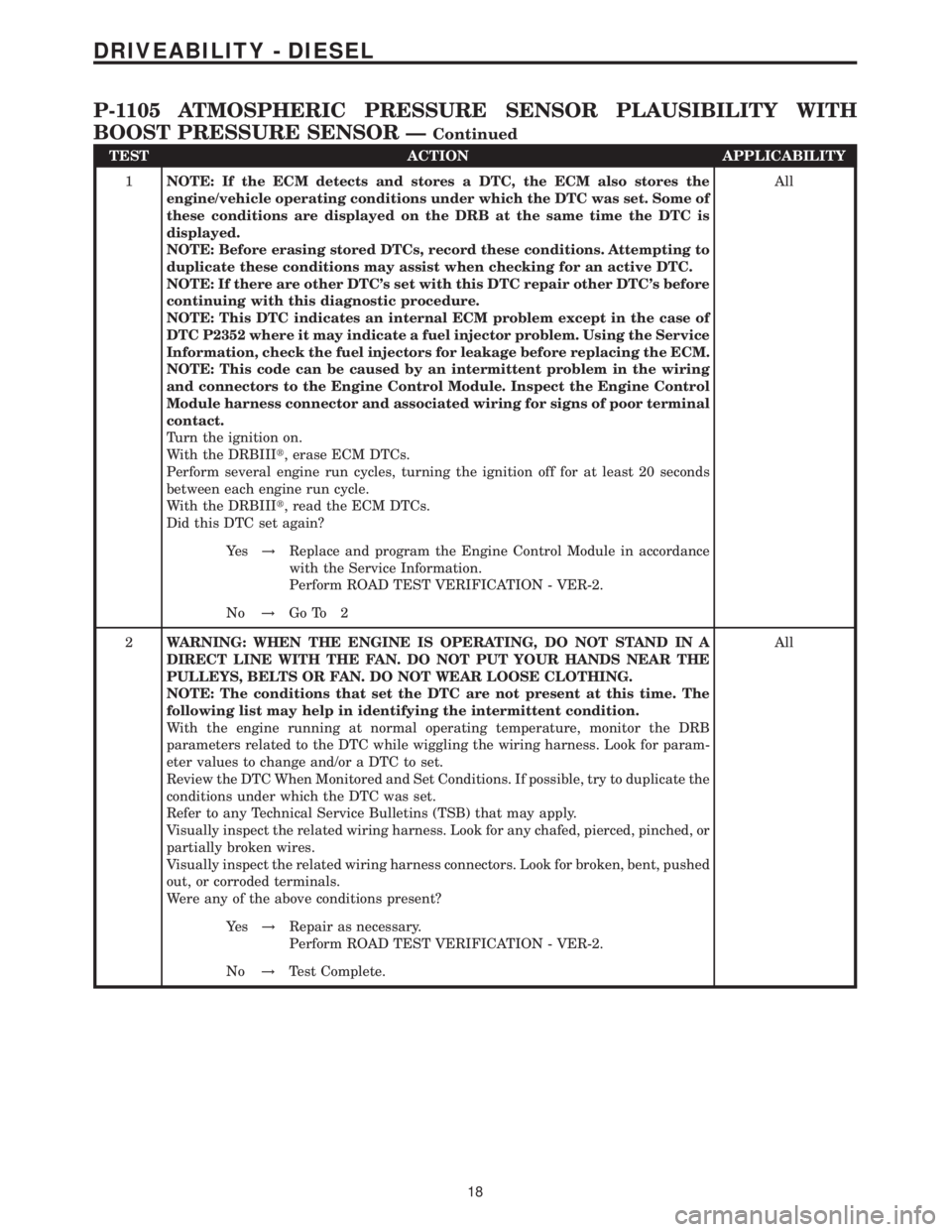
TEST ACTION APPLICABILITY
1NOTE: If the ECM detects and stores a DTC, the ECM also stores the
engine/vehicle operating conditions under which the DTC was set. Some of
these conditions are displayed on the DRB at the same time the DTC is
displayed.
NOTE: Before erasing stored DTCs, record these conditions. Attempting to
duplicate these conditions may assist when checking for an active DTC.
NOTE: If there are other DTC's set with this DTC repair other DTC's before
continuing with this diagnostic procedure.
NOTE: This DTC indicates an internal ECM problem except in the case of
DTC P2352 where it may indicate a fuel injector problem. Using the Service
Information, check the fuel injectors for leakage before replacing the ECM.
NOTE: This code can be caused by an intermittent problem in the wiring
and connectors to the Engine Control Module. Inspect the Engine Control
Module harness connector and associated wiring for signs of poor terminal
contact.
Turn the ignition on.
With the DRBIIIt, erase ECM DTCs.
Perform several engine run cycles, turning the ignition off for at least 20 seconds
between each engine run cycle.
With the DRBIIIt, read the ECM DTCs.
Did this DTC set again?All
Ye s!Replace and program the Engine Control Module in accordance
with the Service Information.
Perform ROAD TEST VERIFICATION - VER-2.
No!Go To 2
2WARNING: WHEN THE ENGINE IS OPERATING, DO NOT STAND IN A
DIRECT LINE WITH THE FAN. DO NOT PUT YOUR HANDS NEAR THE
PULLEYS, BELTS OR FAN. DO NOT WEAR LOOSE CLOTHING.
NOTE: The conditions that set the DTC are not present at this time. The
following list may help in identifying the intermittent condition.
With the engine running at normal operating temperature, monitor the DRB
parameters related to the DTC while wiggling the wiring harness. Look for param-
eter values to change and/or a DTC to set.
Review the DTC When Monitored and Set Conditions. If possible, try to duplicate the
conditions under which the DTC was set.
Refer to any Technical Service Bulletins (TSB) that may apply.
Visually inspect the related wiring harness. Look for any chafed, pierced, pinched, or
partially broken wires.
Visually inspect the related wiring harness connectors. Look for broken, bent, pushed
out, or corroded terminals.
Were any of the above conditions present?All
Ye s!Repair as necessary.
Perform ROAD TEST VERIFICATION - VER-2.
No!Test Complete.
18
DRIVEABILITY - DIESEL
P-1105 ATMOSPHERIC PRESSURE SENSOR PLAUSIBILITY WITH
BOOST PRESSURE SENSOR Ð
Continued
Page 447 of 2305
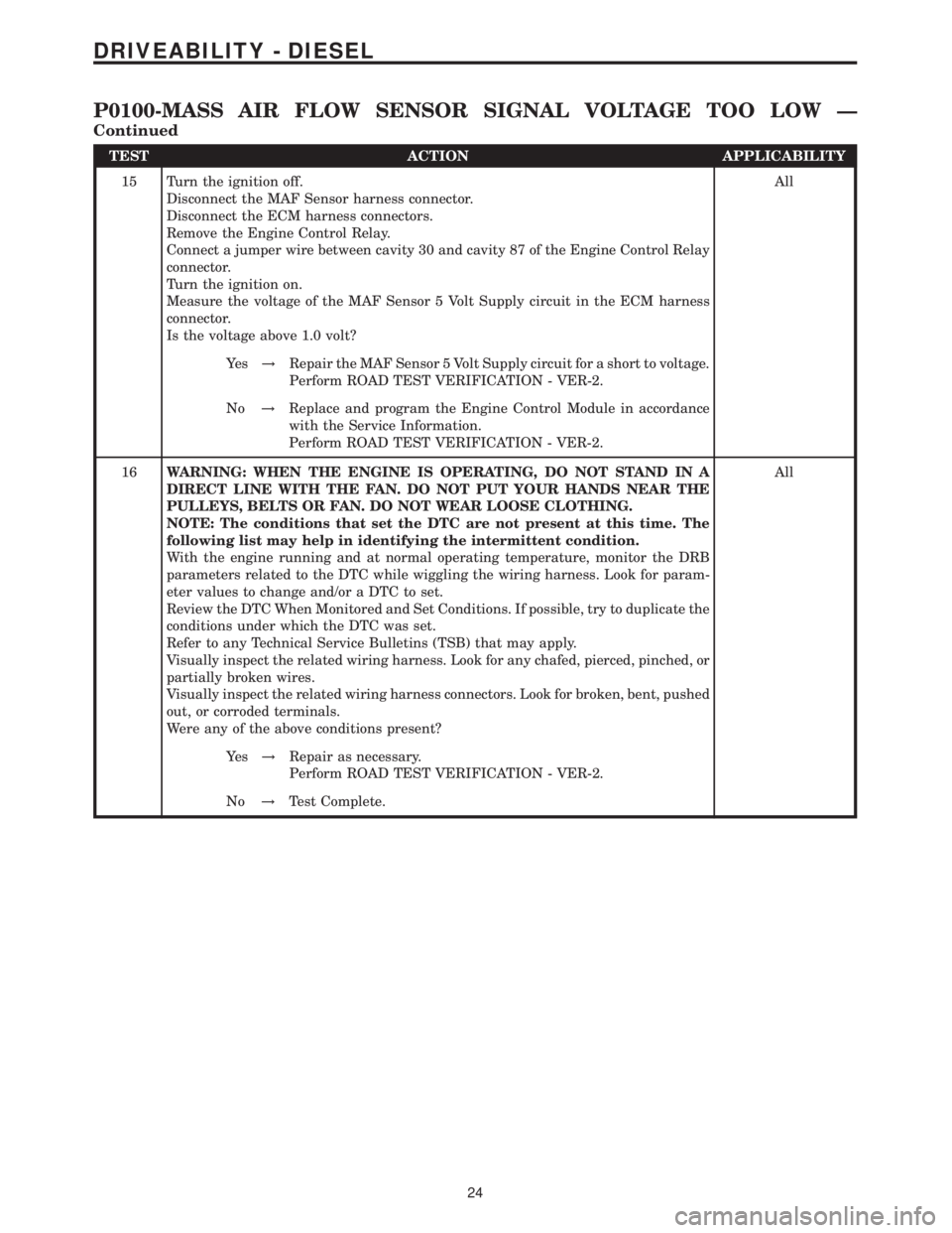
TEST ACTION APPLICABILITY
15 Turn the ignition off.
Disconnect the MAF Sensor harness connector.
Disconnect the ECM harness connectors.
Remove the Engine Control Relay.
Connect a jumper wire between cavity 30 and cavity 87 of the Engine Control Relay
connector.
Turn the ignition on.
Measure the voltage of the MAF Sensor 5 Volt Supply circuit in the ECM harness
connector.
Is the voltage above 1.0 volt?All
Ye s!Repair the MAF Sensor 5 Volt Supply circuit for a short to voltage.
Perform ROAD TEST VERIFICATION - VER-2.
No!Replace and program the Engine Control Module in accordance
with the Service Information.
Perform ROAD TEST VERIFICATION - VER-2.
16WARNING: WHEN THE ENGINE IS OPERATING, DO NOT STAND IN A
DIRECT LINE WITH THE FAN. DO NOT PUT YOUR HANDS NEAR THE
PULLEYS, BELTS OR FAN. DO NOT WEAR LOOSE CLOTHING.
NOTE: The conditions that set the DTC are not present at this time. The
following list may help in identifying the intermittent condition.
With the engine running and at normal operating temperature, monitor the DRB
parameters related to the DTC while wiggling the wiring harness. Look for param-
eter values to change and/or a DTC to set.
Review the DTC When Monitored and Set Conditions. If possible, try to duplicate the
conditions under which the DTC was set.
Refer to any Technical Service Bulletins (TSB) that may apply.
Visually inspect the related wiring harness. Look for any chafed, pierced, pinched, or
partially broken wires.
Visually inspect the related wiring harness connectors. Look for broken, bent, pushed
out, or corroded terminals.
Were any of the above conditions present?All
Ye s!Repair as necessary.
Perform ROAD TEST VERIFICATION - VER-2.
No!Test Complete.
24
DRIVEABILITY - DIESEL
P0100-MASS AIR FLOW SENSOR SIGNAL VOLTAGE TOO LOW Ð
Continued
Page 450 of 2305
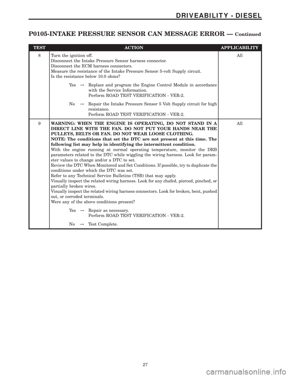
TEST ACTION APPLICABILITY
8 Turn the ignition off.
Disconnect the Intake Pressure Sensor harness connector.
Disconnect the ECM harness connectors.
Measure the resistance of the Intake Pressure Sensor 5-volt Supply circuit.
Is the resistance below 10.0 ohms?All
Ye s!Replace and program the Engine Control Module in accordance
with the Service Information.
Perform ROAD TEST VERIFICATION - VER-2.
No!Repair the Intake Pressure Sensor 5 Volt Supply circuit for high
resistance.
Perform ROAD TEST VERIFICATION - VER-2.
9WARNING: WHEN THE ENGINE IS OPERATING, DO NOT STAND IN A
DIRECT LINE WITH THE FAN. DO NOT PUT YOUR HANDS NEAR THE
PULLEYS, BELTS OR FAN. DO NOT WEAR LOOSE CLOTHING.
NOTE: The conditions that set the DTC are not present at this time. The
following list may help in identifying the intermittent condition.
With the engine running at normal operating temperature, monitor the DRB
parameters related to the DTC while wiggling the wiring harness. Look for param-
eter values to change and/or a DTC to set.
Review the DTC When Monitored and Set Conditions. If possible, try to duplicate the
conditions under which the DTC was set.
Refer to any Technical Service Bulletins (TSB) that may apply.
Visually inspect the related wiring harness. Look for any chafed, pierced, pinched, or
partially broken wires.
Visually inspect the related wiring harness connectors. Look for broken, bent, pushed
out, or corroded terminals.
Were any of the above conditions present?All
Ye s!Repair as necessary.
Perform ROAD TEST VERIFICATION - VER-2.
No!Test Complete.
27
DRIVEABILITY - DIESEL
P0105-INTAKE PRESSURE SENSOR CAN MESSAGE ERROR ÐContinued
Page 453 of 2305
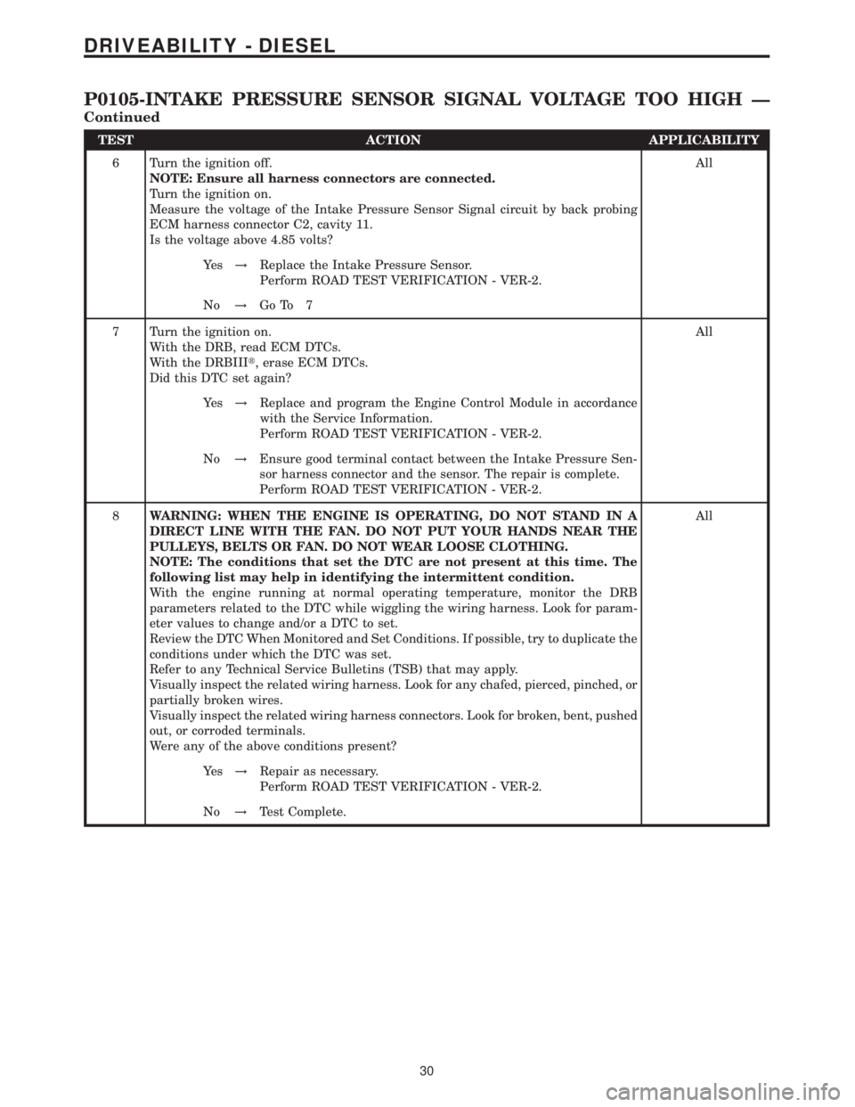
TEST ACTION APPLICABILITY
6 Turn the ignition off.
NOTE: Ensure all harness connectors are connected.
Turn the ignition on.
Measure the voltage of the Intake Pressure Sensor Signal circuit by back probing
ECM harness connector C2, cavity 11.
Is the voltage above 4.85 volts?All
Ye s!Replace the Intake Pressure Sensor.
Perform ROAD TEST VERIFICATION - VER-2.
No!Go To 7
7 Turn the ignition on.
With the DRB, read ECM DTCs.
With the DRBIIIt, erase ECM DTCs.
Did this DTC set again?All
Ye s!Replace and program the Engine Control Module in accordance
with the Service Information.
Perform ROAD TEST VERIFICATION - VER-2.
No!Ensure good terminal contact between the Intake Pressure Sen-
sor harness connector and the sensor. The repair is complete.
Perform ROAD TEST VERIFICATION - VER-2.
8WARNING: WHEN THE ENGINE IS OPERATING, DO NOT STAND IN A
DIRECT LINE WITH THE FAN. DO NOT PUT YOUR HANDS NEAR THE
PULLEYS, BELTS OR FAN. DO NOT WEAR LOOSE CLOTHING.
NOTE: The conditions that set the DTC are not present at this time. The
following list may help in identifying the intermittent condition.
With the engine running at normal operating temperature, monitor the DRB
parameters related to the DTC while wiggling the wiring harness. Look for param-
eter values to change and/or a DTC to set.
Review the DTC When Monitored and Set Conditions. If possible, try to duplicate the
conditions under which the DTC was set.
Refer to any Technical Service Bulletins (TSB) that may apply.
Visually inspect the related wiring harness. Look for any chafed, pierced, pinched, or
partially broken wires.
Visually inspect the related wiring harness connectors. Look for broken, bent, pushed
out, or corroded terminals.
Were any of the above conditions present?All
Ye s!Repair as necessary.
Perform ROAD TEST VERIFICATION - VER-2.
No!Test Complete.
30
DRIVEABILITY - DIESEL
P0105-INTAKE PRESSURE SENSOR SIGNAL VOLTAGE TOO HIGH Ð
Continued
Page 456 of 2305
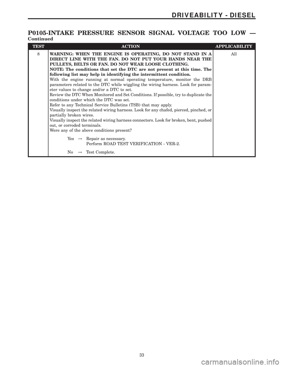
TEST ACTION APPLICABILITY
8WARNING: WHEN THE ENGINE IS OPERATING, DO NOT STAND IN A
DIRECT LINE WITH THE FAN. DO NOT PUT YOUR HANDS NEAR THE
PULLEYS, BELTS OR FAN. DO NOT WEAR LOOSE CLOTHING.
NOTE: The conditions that set the DTC are not present at this time. The
following list may help in identifying the intermittent condition.
With the engine running at normal operating temperature, monitor the DRB
parameters related to the DTC while wiggling the wiring harness. Look for param-
eter values to change and/or a DTC to set.
Review the DTC When Monitored and Set Conditions. If possible, try to duplicate the
conditions under which the DTC was set.
Refer to any Technical Service Bulletins (TSB) that may apply.
Visually inspect the related wiring harness. Look for any chafed, pierced, pinched, or
partially broken wires.
Visually inspect the related wiring harness connectors. Look for broken, bent, pushed
out, or corroded terminals.
Were any of the above conditions present?All
Ye s!Repair as necessary.
Perform ROAD TEST VERIFICATION - VER-2.
No!Test Complete.
33
DRIVEABILITY - DIESEL
P0105-INTAKE PRESSURE SENSOR SIGNAL VOLTAGE TOO LOW Ð
Continued
Page 459 of 2305
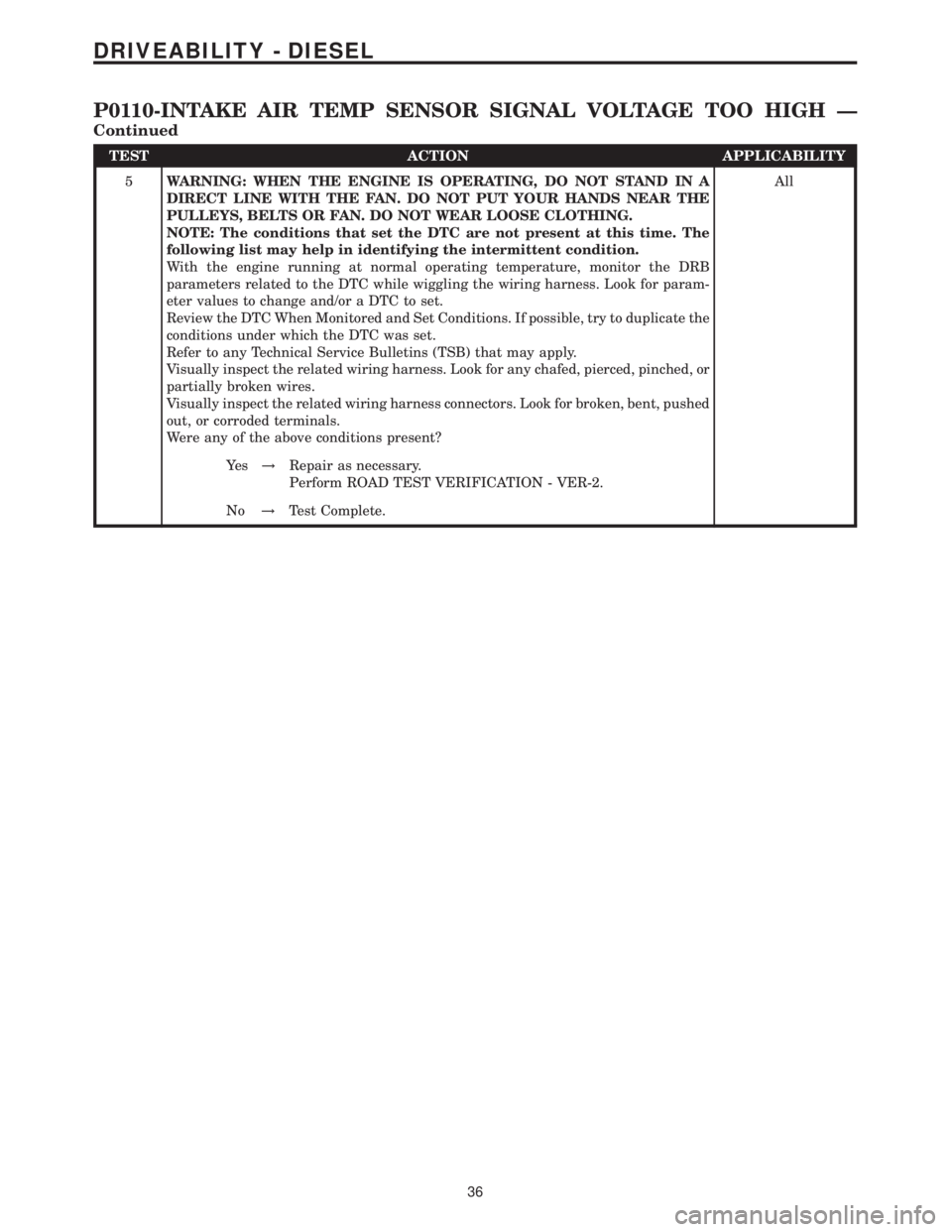
TEST ACTION APPLICABILITY
5WARNING: WHEN THE ENGINE IS OPERATING, DO NOT STAND IN A
DIRECT LINE WITH THE FAN. DO NOT PUT YOUR HANDS NEAR THE
PULLEYS, BELTS OR FAN. DO NOT WEAR LOOSE CLOTHING.
NOTE: The conditions that set the DTC are not present at this time. The
following list may help in identifying the intermittent condition.
With the engine running at normal operating temperature, monitor the DRB
parameters related to the DTC while wiggling the wiring harness. Look for param-
eter values to change and/or a DTC to set.
Review the DTC When Monitored and Set Conditions. If possible, try to duplicate the
conditions under which the DTC was set.
Refer to any Technical Service Bulletins (TSB) that may apply.
Visually inspect the related wiring harness. Look for any chafed, pierced, pinched, or
partially broken wires.
Visually inspect the related wiring harness connectors. Look for broken, bent, pushed
out, or corroded terminals.
Were any of the above conditions present?All
Ye s!Repair as necessary.
Perform ROAD TEST VERIFICATION - VER-2.
No!Test Complete.
36
DRIVEABILITY - DIESEL
P0110-INTAKE AIR TEMP SENSOR SIGNAL VOLTAGE TOO HIGH Ð
Continued