sensor MERCEDES-BENZ SPRINTER 2006 Service Manual
[x] Cancel search | Manufacturer: MERCEDES-BENZ, Model Year: 2006, Model line: SPRINTER, Model: MERCEDES-BENZ SPRINTER 2006Pages: 2305, PDF Size: 48.12 MB
Page 686 of 2305
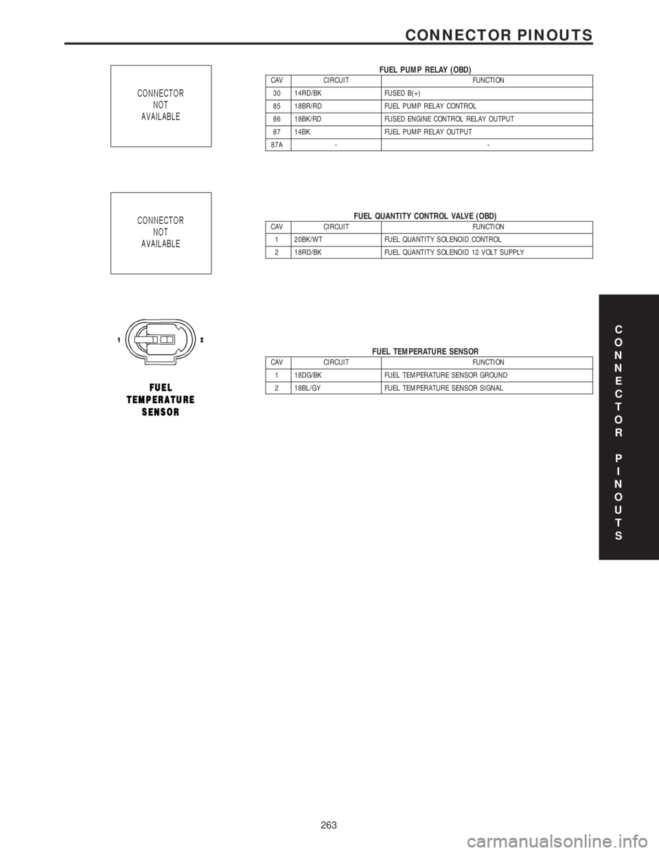
FUEL PUMP RELAY (OBD)CAV CIRCUIT FUNCTION
30 14RD/BK FUSED B(+)
85 18BR/RD FUEL PUMP RELAY CONTROL
86 18BK/RD FUSED ENGINE CONTROL RELAY OUTPUT
87 14BK FUEL PUMP RELAY OUTPUT
87A - -
FUEL QUANTITY CONTROL VALVE (OBD)CAV CIRCUIT FUNCTION
1 20BK/WT FUEL QUANTITY SOLENOID CONTROL
2 18RD/BK FUEL QUANTITY SOLENOID 12 VOLT SUPPLY
FUEL TEMPERATURE SENSORCAV CIRCUIT FUNCTION
1 18DG/BK FUEL TEMPERATURE SENSOR GROUND
2 18BL/GY FUEL TEMPERATURE SENSOR SIGNAL
C
O
N
N
E
C
T
O
R
P
I
N
O
U
T
S
263
CONNECTOR PINOUTS
Page 693 of 2305
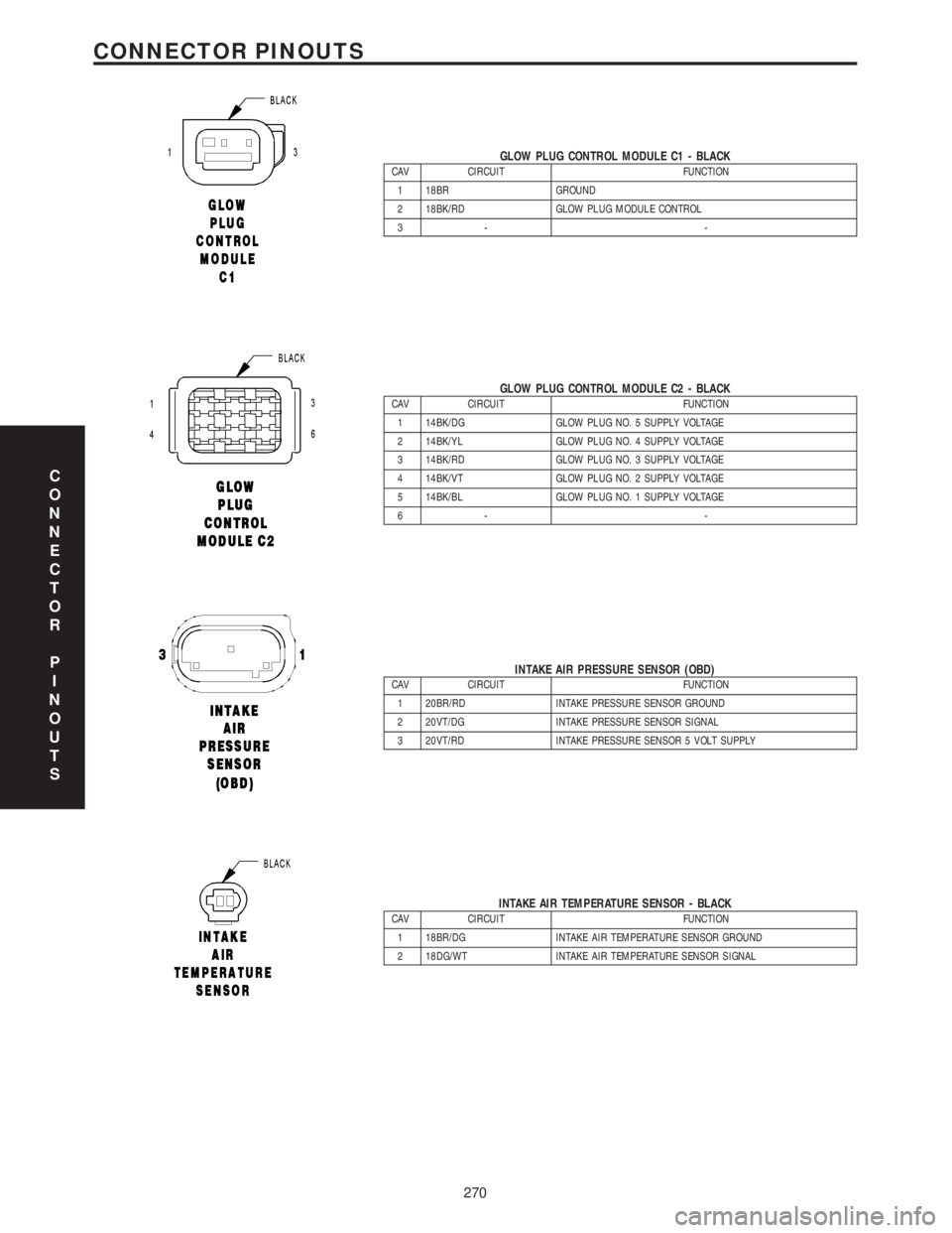
GLOW PLUG CONTROL MODULE C1 - BLACKCAV CIRCUIT FUNCTION
1 18BR GROUND
2 18BK/RD GLOW PLUG MODULE CONTROL
3- -
GLOW PLUG CONTROL MODULE C2 - BLACKCAV CIRCUIT FUNCTION
1 14BK/DG GLOW PLUG NO. 5 SUPPLY VOLTAGE
2 14BK/YL GLOW PLUG NO. 4 SUPPLY VOLTAGE
3 14BK/RD GLOW PLUG NO. 3 SUPPLY VOLTAGE
4 14BK/VT GLOW PLUG NO. 2 SUPPLY VOLTAGE
5 14BK/BL GLOW PLUG NO. 1 SUPPLY VOLTAGE
6- -
INTAKE AIR PRESSURE SENSOR (OBD)CAV CIRCUIT FUNCTION
1 20BR/RD INTAKE PRESSURE SENSOR GROUND
2 20VT/DG INTAKE PRESSURE SENSOR SIGNAL
3 20VT/RD INTAKE PRESSURE SENSOR 5 VOLT SUPPLY
INTAKE AIR TEMPERATURE SENSOR - BLACKCAV CIRCUIT FUNCTION
1 18BR/DG INTAKE AIR TEMPERATURE SENSOR GROUND
2 18DG/WT INTAKE AIR TEMPERATURE SENSOR SIGNAL
C
O
N
N
E
C
T
O
R
P
I
N
O
U
T
S
270
CONNECTOR PINOUTS
Page 694 of 2305
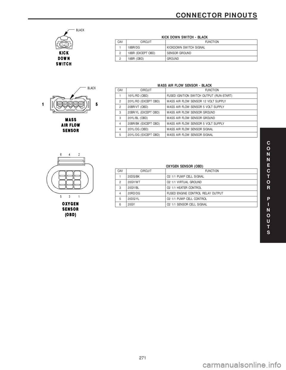
KICK DOWN SWITCH - BLACKCAV CIRCUIT FUNCTION
1 18BR/DG KICKDOWN SWITCH SIGNAL
2 18BR (EXCEPT OBD) SENSOR GROUND
2 18BR (OBD) GROUND
MASS AIR FLOW SENSOR - BLACKCAV CIRCUIT FUNCTION
1 16YL/RD (OBD) FUSED IGNITION SWITCH OUTPUT (RUN-START)
2 20YL/RD (EXCEPT OBD) MASS AIR FLOW SENSOR 12 VOLT SUPPLY
2 20BR/VT (OBD) MASS AIR FLOW SENSOR 5 VOLT SUPPLY
3 20BR/YL (EXCEPT OBD) MASS AIR FLOW SENSOR GROUND
3 20YL/BL (OBD) MASS AIR FLOW SENSOR GROUND
4 20BR/BK (EXCEPT OBD) MASS AIR FLOW SENSOR 5 VOLT SUPPLY
4 20YL/DG (OBD) MASS AIR FLOW SENSOR SIGNAL
5 20YL/DG (EXCEPT OBD) MASS AIR FLOW SENSOR SIGNAL
OXYGEN SENSOR (OBD)CAV CIRCUIT FUNCTION
1 20DG/BK O2 1/1 PUMP CELL SIGNAL
2 20GY/WT O2 1/1 VIRTUAL GROUND
3 20GY/BL O2 1/1 HEATER CONTROL
4 20RD/DG FUSED ENGINE CONTROL RELAY OUTPUT
5 20DG/YL O2 1/1 PUMP CELL CONTROL
6 20GY O2 1/1 SENSOR CELL SIGNAL
C
O
N
N
E
C
T
O
R
P
I
N
O
U
T
S
271
CONNECTOR PINOUTS
Page 696 of 2305
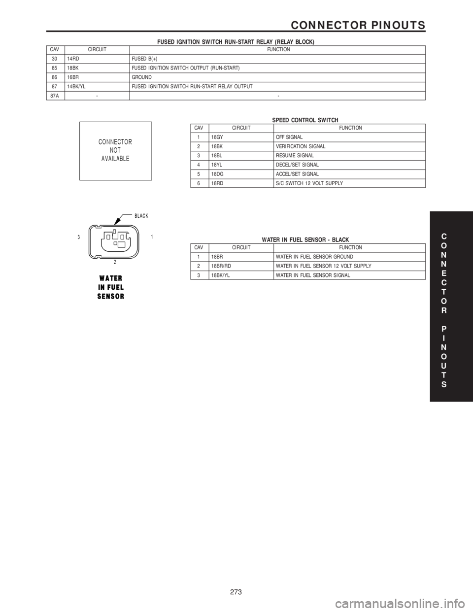
FUSED IGNITION SWITCH RUN-START RELAY (RELAY BLOCK)CAV CIRCUIT FUNCTION
30 14RD FUSED B(+)
85 18BK FUSED IGNITION SWITCH OUTPUT (RUN-START)
86 16BR GROUND
87 14BK/YL FUSED IGNITION SWITCH RUN-START RELAY OUTPUT
87A --
SPEED CONTROL SWITCHCAV CIRCUIT FUNCTION
1 18GY OFF SIGNAL
2 18BK VERIFICATION SIGNAL
3 18BL RESUME SIGNAL
4 18YL DECEL/SET SIGNAL
5 18DG ACCEL/SET SIGNAL
6 18RD S/C SWITCH 12 VOLT SUPPLY
WATER IN FUEL SENSOR - BLACKCAV CIRCUIT FUNCTION
1 18BR WATER IN FUEL SENSOR GROUND
2 18BR/RD WATER IN FUEL SENSOR 12 VOLT SUPPLY
3 18BK/YL WATER IN FUEL SENSOR SIGNAL
C
O
N
N
E
C
T
O
R
P
I
N
O
U
T
S
273
CONNECTOR PINOUTS
Page 724 of 2305
SCOPE OF WORK FOR MAINTENANCE SERVICE
Oil Service
²Engine: Oil change and filter replacement
Check fluid levels of the following system, refill as neces-
sary.
²If fluid is lost, trace and eliminate cause - as a
separate order.
²Power-assisted steering
Lubrication work:
²Trailer tow hitch (original equipment)
Maintenance
²ASSYST maintenance computer reset
Function check
²Signalling system, warning and indicator lamps
²Headlamps, exterior lighting
²Windshield wipers, windshield washer system
Check for leaks and damage
²Check for abrasion points and ensure that lines
are correctly routed!
²All lines and hoses, sensor cables
²Rubber boots on front axle drive shafts, rubber
boots on front axle suspension ball joints, shock
absorbers
²Check fluid levels for the following systems, cor-
rect as necessary
NOTE: Should there be a loss of fluid which cannot
be explained by regular use, trace and eliminate the
cause.
²Engine cooling system. Check corrosion inhibi-
tor/antifreeze, refill as necessary.
²Hydraulic brake system
²Battery
²Windshield washer system
Engine
²Fuel filter renewal - Every oil service
²Air cleaner with maintenance indicator:
²Check degree of contamination.
²Air cleaner filter element renewed as necessary.
Chassis and body
²Trailer coupling: Check operation, play and
retaining fixtures
²Secondary rubber springs: Visual check
²Tire pressures: Correct as necessary, including
spare tire
²Check thickness of brake pads
²Brake test
²Check condition of steering mechanism
²Heating/ventilation dust filter renewal
ADDITIONAL MAINTENANCE WORK
Automatic transmission once only at 80,000 miles / 128000
km
²Oil and filter change
During every second maintenance service
²Air cleaner without maintenance indicator:
²Air cleaner filter element renewal
²Check poly-V-belt for wear and signs of damage
During every fourth maintenance service
²Change rear axle fluid
ADDITIONAL MAINTENANCE WORK AFTER YEARS
Every 2 years
²Change brake fluid.
Every 3 years
²Air cleaner filter element renewal (note installa-
tion date)
Every 15 years or 100,000 miles
²Coolant renewal
²Note coolant composition
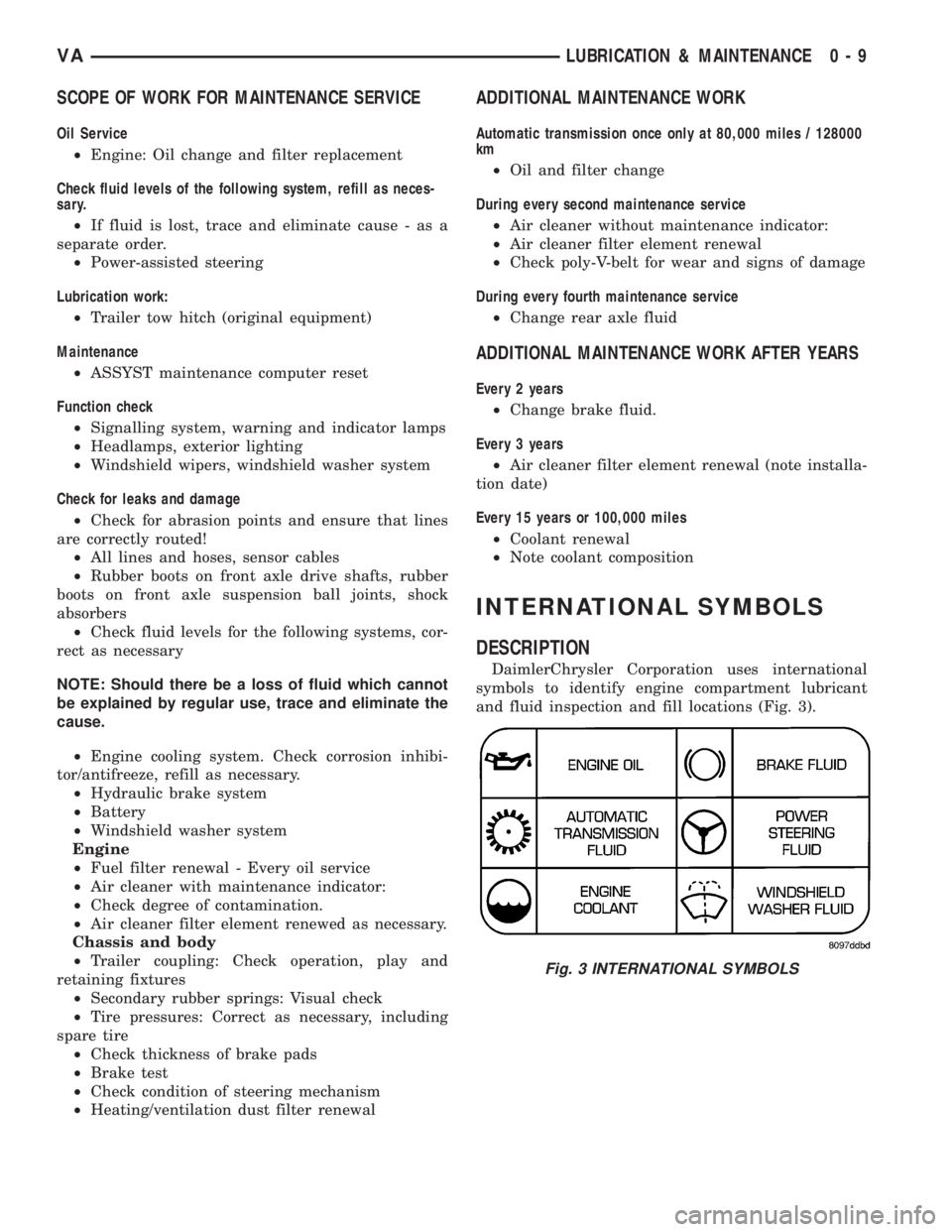
INTERNATIONAL SYMBOLS
DESCRIPTION
DaimlerChrysler Corporation uses international
symbols to identify engine compartment lubricant
and fluid inspection and fill locations (Fig. 3).
Fig. 3 INTERNATIONAL SYMBOLS
VALUBRICATION & MAINTENANCE 0 - 9
Page 730 of 2305
INSTALLATION
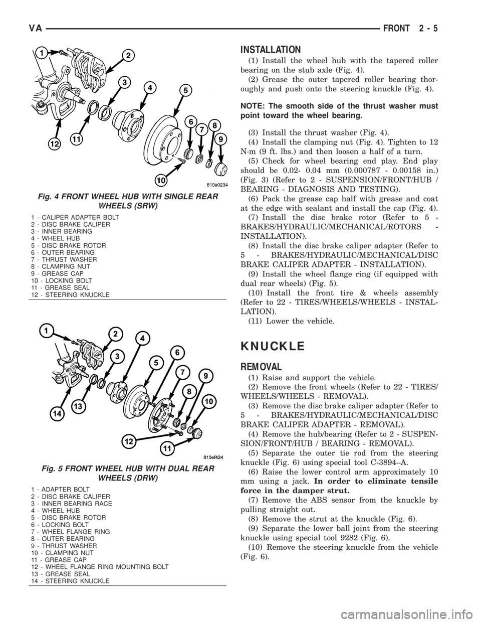
(1) Install the wheel hub with the tapered roller
bearing on the stub axle (Fig. 4).
(2) Grease the outer tapered roller bearing thor-
oughly and push onto the steering knuckle (Fig. 4).
NOTE: The smooth side of the thrust washer must
point toward the wheel bearing.
(3) Install the thrust washer (Fig. 4).
(4) Install the clamping nut (Fig. 4). Tighten to 12
N´m (9 ft. lbs.) and then loosen a half of a turn.
(5) Check for wheel bearing end play. End play
should be 0.02- 0.04 mm (0.000787 - 0.00158 in.)
(Fig. 3) (Refer to 2 - SUSPENSION/FRONT/HUB /
BEARING - DIAGNOSIS AND TESTING).
(6) Pack the grease cap half with grease and coat
at the edge with sealant and install the cap (Fig. 4).
(7) Install the disc brake rotor (Refer to 5 -
BRAKES/HYDRAULIC/MECHANICAL/ROTORS -
INSTALLATION).
(8) Install the disc brake caliper adapter (Refer to
5 - BRAKES/HYDRAULIC/MECHANICAL/DISC
BRAKE CALIPER ADAPTER - INSTALLATION).
(9) Install the wheel flange ring (if equipped with
dual rear wheels) (Fig. 5).
(10) Install the front tire & wheels assembly
(Refer to 22 - TIRES/WHEELS/WHEELS - INSTAL-
LATION).
(11) Lower the vehicle.
KNUCKLE
REMOVAL
(1) Raise and support the vehicle.
(2) Remove the front wheels (Refer to 22 - TIRES/
WHEELS/WHEELS - REMOVAL).
(3) Remove the disc brake caliper adapter (Refer to
5 - BRAKES/HYDRAULIC/MECHANICAL/DISC
BRAKE CALIPER ADAPTER - REMOVAL).
(4) Remove the hub/bearing (Refer to 2 - SUSPEN-
SION/FRONT/HUB / BEARING - REMOVAL).
(5) Separate the outer tie rod from the steering
knuckle (Fig. 6) using special tool C-3894±A.
(6) Raise the lower control arm approximately 10
mm using a jack.In order to eliminate tensile
force in the damper strut.
(7) Remove the ABS sensor from the knuckle by
pulling straight out.
(8) Remove the strut at the knuckle (Fig. 6).
(9) Separate the lower ball joint from the steering
knuckle using special tool 9282 (Fig. 6).
(10) Remove the steering knuckle from the vehicle
(Fig. 6).
Fig. 4 FRONT WHEEL HUB WITH SINGLE REAR
WHEELS (SRW)
1 - CALIPER ADAPTER BOLT
2 - DISC BRAKE CALIPER
3 - INNER BEARING
4 - WHEEL HUB
5 - DISC BRAKE ROTOR
6 - OUTER BEARING
7 - THRUST WASHER
8 - CLAMPING NUT
9 - GREASE CAP
10 - LOCKING BOLT
11 - GREASE SEAL
12 - STEERING KNUCKLE
Fig. 5 FRONT WHEEL HUB WITH DUAL REAR
WHEELS (DRW)
1 - ADAPTER BOLT
2 - DISC BRAKE CALIPER
3 - INNER BEARING RACE
4 - WHEEL HUB
5 - DISC BRAKE ROTOR
6 - LOCKING BOLT
7 - WHEEL FLANGE RING
8 - OUTER BEARING
9 - THRUST WASHER
10 - CLAMPING NUT
11 - GREASE CAP
12 - WHEEL FLANGE RING MOUNTING BOLT
13 - GREASE SEAL
14 - STEERING KNUCKLE
VAFRONT 2 - 5
Page 731 of 2305
INSTALLATION
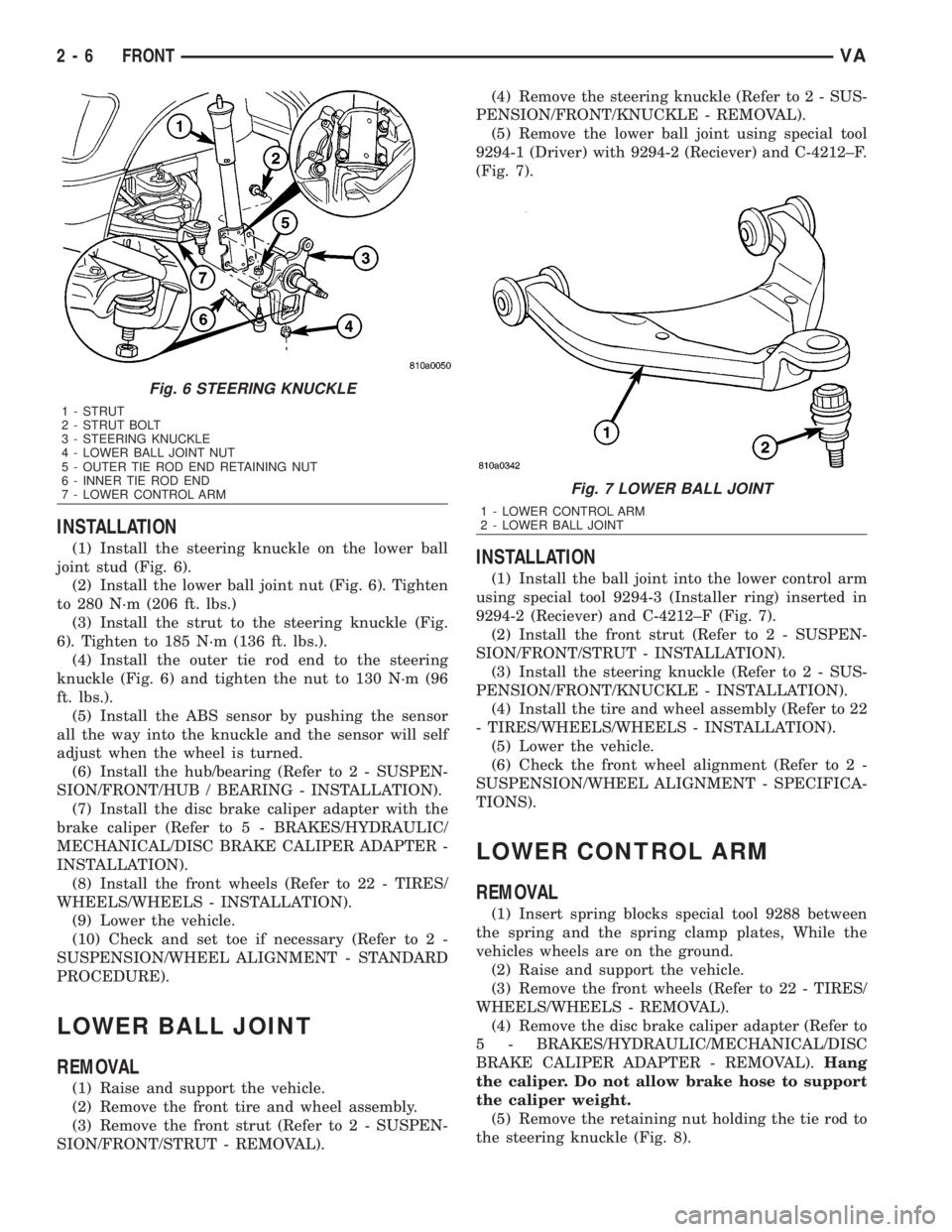
(1) Install the steering knuckle on the lower ball
joint stud (Fig. 6).
(2) Install the lower ball joint nut (Fig. 6). Tighten
to 280 N´m (206 ft. lbs.)
(3) Install the strut to the steering knuckle (Fig.
6). Tighten to 185 N´m (136 ft. lbs.).
(4) Install the outer tie rod end to the steering
knuckle (Fig. 6) and tighten the nut to 130 N´m (96
ft. lbs.).
(5) Install the ABS sensor by pushing the sensor
all the way into the knuckle and the sensor will self
adjust when the wheel is turned.
(6) Install the hub/bearing (Refer to 2 - SUSPEN-
SION/FRONT/HUB / BEARING - INSTALLATION).
(7) Install the disc brake caliper adapter with the
brake caliper (Refer to 5 - BRAKES/HYDRAULIC/
MECHANICAL/DISC BRAKE CALIPER ADAPTER -
INSTALLATION).
(8) Install the front wheels (Refer to 22 - TIRES/
WHEELS/WHEELS - INSTALLATION).
(9) Lower the vehicle.
(10) Check and set toe if necessary (Refer to 2 -
SUSPENSION/WHEEL ALIGNMENT - STANDARD
PROCEDURE).
LOWER BALL JOINT
REMOVAL
(1) Raise and support the vehicle.
(2) Remove the front tire and wheel assembly.
(3) Remove the front strut (Refer to 2 - SUSPEN-
SION/FRONT/STRUT - REMOVAL).(4) Remove the steering knuckle (Refer to 2 - SUS-
PENSION/FRONT/KNUCKLE - REMOVAL).
(5) Remove the lower ball joint using special tool
9294-1 (Driver) with 9294-2 (Reciever) and C-4212±F.
(Fig. 7).
INSTALLATION
(1) Install the ball joint into the lower control arm
using special tool 9294-3 (Installer ring) inserted in
9294-2 (Reciever) and C-4212±F (Fig. 7).
(2) Install the front strut (Refer to 2 - SUSPEN-
SION/FRONT/STRUT - INSTALLATION).
(3) Install the steering knuckle (Refer to 2 - SUS-
PENSION/FRONT/KNUCKLE - INSTALLATION).
(4) Install the tire and wheel assembly (Refer to 22
- TIRES/WHEELS/WHEELS - INSTALLATION).
(5) Lower the vehicle.
(6) Check the front wheel alignment (Refer to 2 -
SUSPENSION/WHEEL ALIGNMENT - SPECIFICA-
TIONS).
LOWER CONTROL ARM
REMOVAL
(1) Insert spring blocks special tool 9288 between
the spring and the spring clamp plates, While the
vehicles wheels are on the ground.
(2) Raise and support the vehicle.
(3) Remove the front wheels (Refer to 22 - TIRES/
WHEELS/WHEELS - REMOVAL).
(4) Remove the disc brake caliper adapter (Refer to
5 - BRAKES/HYDRAULIC/MECHANICAL/DISC
BRAKE CALIPER ADAPTER - REMOVAL).Hang
the caliper. Do not allow brake hose to support
the caliper weight.
(5) Remove the retaining nut holding the tie rod to
the steering knuckle (Fig. 8).
Fig. 6 STEERING KNUCKLE
1 - STRUT
2 - STRUT BOLT
3 - STEERING KNUCKLE
4 - LOWER BALL JOINT NUT
5 - OUTER TIE ROD END RETAINING NUT
6 - INNER TIE ROD END
7 - LOWER CONTROL ARM
Fig. 7 LOWER BALL JOINT
1 - LOWER CONTROL ARM
2 - LOWER BALL JOINT
2 - 6 FRONTVA
Page 732 of 2305
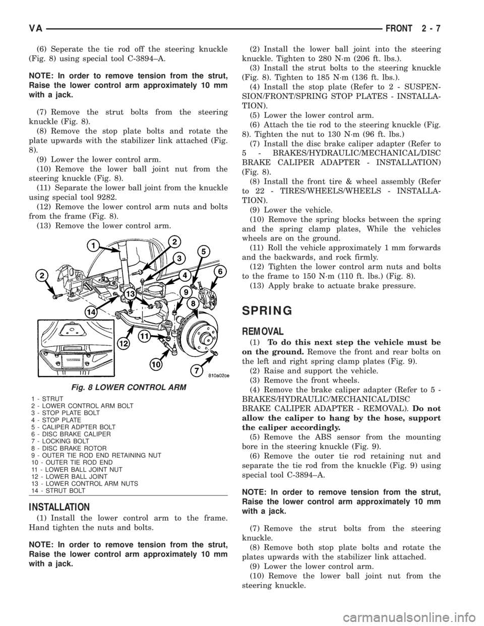
(6) Seperate the tie rod off the steering knuckle
(Fig. 8) using special tool C-3894±A.
NOTE: In order to remove tension from the strut,
Raise the lower control arm approximately 10 mm
with a jack.
(7) Remove the strut bolts from the steering
knuckle (Fig. 8).
(8) Remove the stop plate bolts and rotate the
plate upwards with the stabilizer link attached (Fig.
8).
(9) Lower the lower control arm.
(10) Remove the lower ball joint nut from the
steering knuckle (Fig. 8).
(11) Separate the lower ball joint from the knuckle
using special tool 9282.
(12) Remove the lower control arm nuts and bolts
from the frame (Fig. 8).
(13) Remove the lower control arm.
INSTALLATION
(1) Install the lower control arm to the frame.
Hand tighten the nuts and bolts.
NOTE: In order to remove tension from the strut,
Raise the lower control arm approximately 10 mm
with a jack.(2) Install the lower ball joint into the steering
knuckle. Tighten to 280 N´m (206 ft. lbs.).
(3) Install the strut bolts to the steering knuckle
(Fig. 8). Tighten to 185 N´m (136 ft. lbs.).
(4) Install the stop plate (Refer to 2 - SUSPEN-
SION/FRONT/SPRING STOP PLATES - INSTALLA-
TION).
(5) Lower the lower control arm.
(6) Attach the tie rod to the steering knuckle (Fig.
8). Tighten the nut to 130 N´m (96 ft. lbs.)
(7) Install the disc brake caliper adapter (Refer to
5 - BRAKES/HYDRAULIC/MECHANICAL/DISC
BRAKE CALIPER ADAPTER - INSTALLATION)
(Fig. 8).
(8) Install the front tire & wheel assembly (Refer
to 22 - TIRES/WHEELS/WHEELS - INSTALLA-
TION).
(9) Lower the vehicle.
(10) Remove the spring blocks between the spring
and the spring clamp plates, While the vehicles
wheels are on the ground.
(11) Roll the vehicle approximately 1 mm forwards
and the backwards, and rock firmly.
(12) Tighten the lower control arm nuts and bolts
to the frame to 150 N´m (110 ft. lbs.) (Fig. 8).
(13) Apply brake to actuate brake pressure.
SPRING
REMOVAL
(1)To do this next step the vehicle must be
on the ground.Remove the front and rear bolts on
the left and right spring clamp plates (Fig. 9).
(2) Raise and support the vehicle.
(3) Remove the front wheels.
(4) Remove the brake caliper adapter (Refer to 5 -
BRAKES/HYDRAULIC/MECHANICAL/DISC
BRAKE CALIPER ADAPTER - REMOVAL).Do not
allow the caliper to hang by the hose, support
the caliper accordingly.
(5) Remove the ABS sensor from the mounting
bore in the steering knuckle (Fig. 9).
(6) Remove the outer tie rod retaining nut and
separate the tie rod from the knuckle (Fig. 9) using
special tool C-3894±A.
NOTE: In order to remove tension from the strut,
Raise the lower control arm approximately 10 mm
with a jack.
(7) Remove the strut bolts from the steering
knuckle.
(8) Remove both stop plate bolts and rotate the
plates upwards with the stabilizer link attached.
(9) Lower the lower control arm.
(10) Remove the lower ball joint nut from the
steering knuckle.
Fig. 8 LOWER CONTROL ARM
1 - STRUT
2 - LOWER CONTROL ARM BOLT
3 - STOP PLATE BOLT
4 - STOP PLATE
5 - CALIPER ADPTER BOLT
6 - DISC BRAKE CALIPER
7 - LOCKING BOLT
8 - DISC BRAKE ROTOR
9 - OUTER TIE ROD END RETAINING NUT
10 - OUTER TIE ROD END
11 - LOWER BALL JOINT NUT
12 - LOWER BALL JOINT
13 - LOWER CONTROL ARM NUTS
14 - STRUT BOLT
VAFRONT 2 - 7
Page 733 of 2305
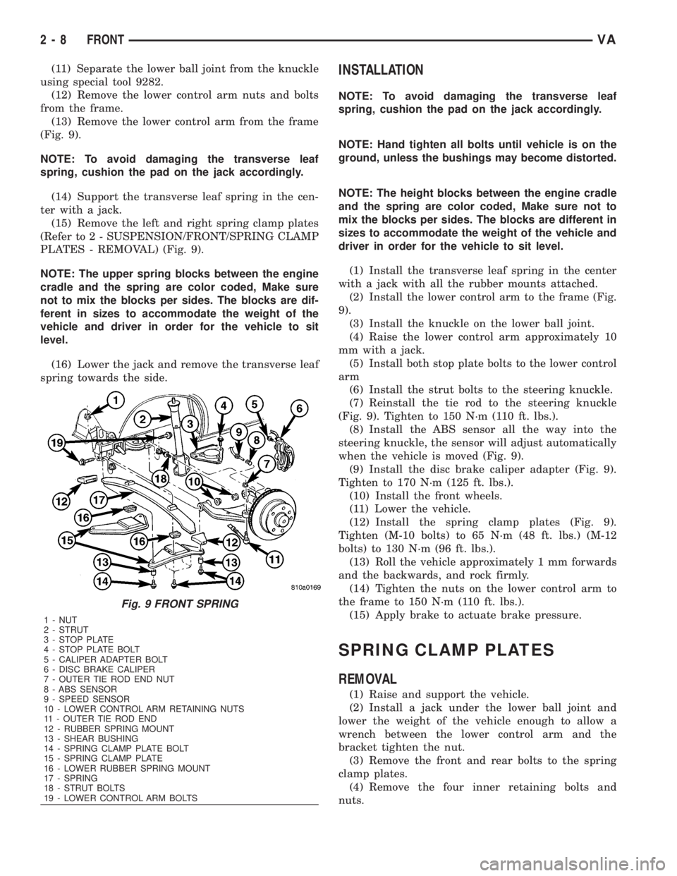
(11) Separate the lower ball joint from the knuckle
using special tool 9282.
(12) Remove the lower control arm nuts and bolts
from the frame.
(13) Remove the lower control arm from the frame
(Fig. 9).
NOTE: To avoid damaging the transverse leaf
spring, cushion the pad on the jack accordingly.
(14) Support the transverse leaf spring in the cen-
ter with a jack.
(15) Remove the left and right spring clamp plates
(Refer to 2 - SUSPENSION/FRONT/SPRING CLAMP
PLATES - REMOVAL) (Fig. 9).
NOTE: The upper spring blocks between the engine
cradle and the spring are color coded, Make sure
not to mix the blocks per sides. The blocks are dif-
ferent in sizes to accommodate the weight of the
vehicle and driver in order for the vehicle to sit
level.
(16) Lower the jack and remove the transverse leaf
spring towards the side.INSTALLATION
NOTE: To avoid damaging the transverse leaf
spring, cushion the pad on the jack accordingly.
NOTE: Hand tighten all bolts until vehicle is on the
ground, unless the bushings may become distorted.
NOTE: The height blocks between the engine cradle
and the spring are color coded, Make sure not to
mix the blocks per sides. The blocks are different in
sizes to accommodate the weight of the vehicle and
driver in order for the vehicle to sit level.
(1) Install the transverse leaf spring in the center
with a jack with all the rubber mounts attached.
(2) Install the lower control arm to the frame (Fig.
9).
(3) Install the knuckle on the lower ball joint.
(4) Raise the lower control arm approximately 10
mm with a jack.
(5) Install both stop plate bolts to the lower control
arm
(6) Install the strut bolts to the steering knuckle.
(7) Reinstall the tie rod to the steering knuckle
(Fig. 9). Tighten to 150 N´m (110 ft. lbs.).
(8) Install the ABS sensor all the way into the
steering knuckle, the sensor will adjust automatically
when the vehicle is moved (Fig. 9).
(9) Install the disc brake caliper adapter (Fig. 9).
Tighten to 170 N´m (125 ft. lbs.).
(10) Install the front wheels.
(11) Lower the vehicle.
(12) Install the spring clamp plates (Fig. 9).
Tighten (M-10 bolts) to 65 N´m (48 ft. lbs.) (M-12
bolts) to 130 N´m (96 ft. lbs.).
(13) Roll the vehicle approximately 1 mm forwards
and the backwards, and rock firmly.
(14) Tighten the nuts on the lower control arm to
the frame to 150 N´m (110 ft. lbs.).
(15) Apply brake to actuate brake pressure.
SPRING CLAMP PLATES
REMOVAL
(1) Raise and support the vehicle.
(2) Install a jack under the lower ball joint and
lower the weight of the vehicle enough to allow a
wrench between the lower control arm and the
bracket tighten the nut.
(3) Remove the front and rear bolts to the spring
clamp plates.
(4) Remove the four inner retaining bolts and
nuts.
Fig. 9 FRONT SPRING
1 - NUT
2 - STRUT
3 - STOP PLATE
4 - STOP PLATE BOLT
5 - CALIPER ADAPTER BOLT
6 - DISC BRAKE CALIPER
7 - OUTER TIE ROD END NUT
8 - ABS SENSOR
9 - SPEED SENSOR
10 - LOWER CONTROL ARM RETAINING NUTS
11 - OUTER TIE ROD END
12 - RUBBER SPRING MOUNT
13 - SHEAR BUSHING
14 - SPRING CLAMP PLATE BOLT
15 - SPRING CLAMP PLATE
16 - LOWER RUBBER SPRING MOUNT
17 - SPRING
18 - STRUT BOLTS
19 - LOWER CONTROL ARM BOLTS
2 - 8 FRONTVA
Page 759 of 2305
REMOVAL
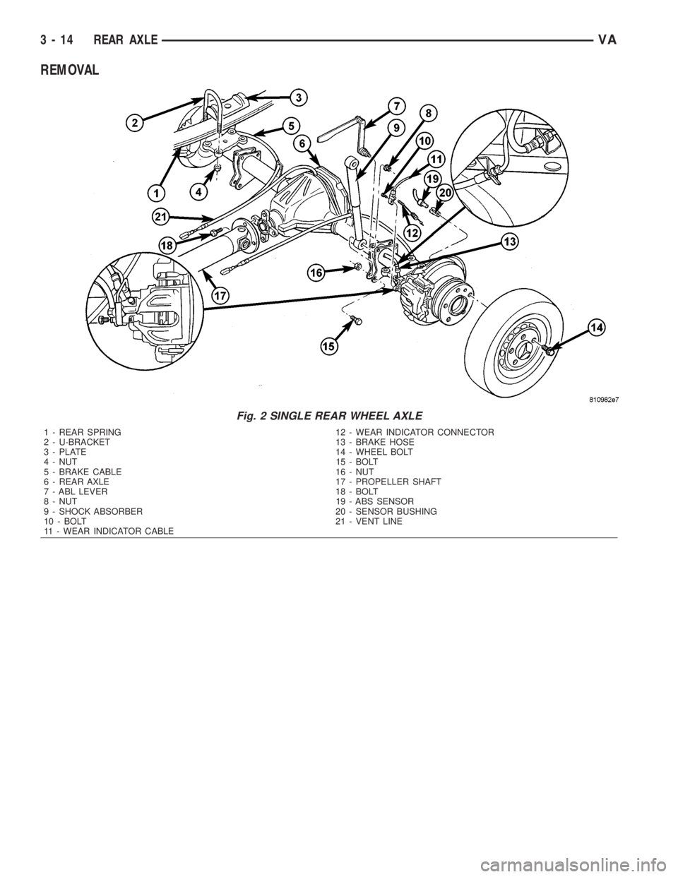
Fig. 2 SINGLE REAR WHEEL AXLE
1 - REAR SPRING 12 - WEAR INDICATOR CONNECTOR
2 - U-BRACKET 13 - BRAKE HOSE
3 - PLATE 14 - WHEEL BOLT
4 - NUT 15 - BOLT
5 - BRAKE CABLE 16 - NUT
6 - REAR AXLE 17 - PROPELLER SHAFT
7 - ABL LEVER 18 - BOLT
8 - NUT 19 - ABS SENSOR
9 - SHOCK ABSORBER 20 - SENSOR BUSHING
10 - BOLT 21 - VENT LINE
11 - WEAR INDICATOR CABLE
3 - 14 REAR AXLEVA