turn signal MERCEDES-BENZ SPRINTER 2006 Owner's Guide
[x] Cancel search | Manufacturer: MERCEDES-BENZ, Model Year: 2006, Model line: SPRINTER, Model: MERCEDES-BENZ SPRINTER 2006Pages: 2305, PDF Size: 48.12 MB
Page 322 of 2305
1.0 INTRODUCTION
The procedures contained in this manual include
all the specifications, instructions, and graphics
needed to diagnose the Sprinter Chassis system
problems: Bosch 5.7 ABS/ESP/TCS (ASR) Braking
System. The diagnostics in this manual are based
on the failure condition or symptom being present
at time of diagnosis.
Please follow the recommendations below when
choosing your diagnostic path.
1. First make sure the DRBIIItis communicating
with the vehicle system being diagnosed. If the
DRBIIItdisplays a ``No Response'' condition, you
must diagnose that first.
2. Read DTC's (diagnostic trouble codes) with the
DRBIIIt.
3. If no DTC's are present, identify the customer
complaint.
4. Once the DTC or customer complaint is iden-
tified locate the matching test in the Table of
Contents and begin to diagnose the system.
All component location views are in Section 8.0.
All connector pinouts are in Section 9.0. All sche-
matics are in Section 10.0.
When repairs are required, refer to the appropri-
ate service manual for the proper removal and
repair procedure.
Diagnostic procedures change every year. New
diagnostic systems may be added; carryover sys-
tems maybe enhanced. READ THIS MANUAL BE-
FORE TRYING TO DIAGNOSE A VEHICLE DI-
AGNOSTIC TROUBLE CODE. It is recommended
that you review the entire manual to become famil-
iar with all new and changed diagnostic procedures.
This manual reflects many suggested changes
from readers of past issues. After using this man-
ual, if you have any comments or recommendations,
please fill out the form at the back of the manual
and mail it back.
1.1 SYSTEM COVERAGE
This diagnostic procedure manual covers the An-
tilock Braking System (ABS), the Electronic Stabil-
ity Program (ESP) and the Traction Control System
(TCS) found on the Sprinter.
1.2 SIX-STEP TROUBLESHOOTING
PROCEDURE
Diagnosis of the Antilock Brake Systems is done
in six basic steps:
²Verification of complaint
²Verification of any related symptoms
²Symptom analysis
²Problem isolation
²Repair of isolated problem
²Verification of proper operation
2.0 INDENTIFICATION OF
SYSTEM
The Bosch 5.7 system can be identified by the 42
way Controller Antilock Brake (CAB), Hydraulic
Control Unit (HCU) and Pump Motor being an
integral electronic/hydraulic unit mounted below
the Master Cylinder with four Wheel Speed Sen-
sors, one at each wheel.
Vehicles with the Traction Control System (TCS/
ASR) can be identified by the presence of the
Traction Control System Switch (TCCS) located on
the center instrument panel.
Vehicles with Electronic Stability Program (ESP)
can be identified by the presence of the Steering
Angle Sensor and the Lateral Acceleration/Yaw
Sensor.
3.0 SYSTEM DESCRIPTION AND
FUNCTIONAL OPERATION
3.1 ESP
The ESP system consists of the electronic control/
hydraulic unit, steering angle sensor, lateral
acceleration/yaw sensor and wheel speed sensors.
When the vehicle is in a turn, the ESP looks at the
steering wheel angle sensor value and monitors the
wheel speed of the inner and outer wheels to ensure
the values are plausible. The steering angle sensor
also measures the speed at which the steering
wheel is turned.
The ESP control module is very similar to the
ABS/ASR module. The ESP is comprised of several
other systems, namely theHBA, ABS, TCS (ASR),
EBDandFZRsystems.
3.2 ABS
The Controller Antilock Brake (CAB) is used to
monitor wheel speeds and modulates (controls) hy-
draulic pressure in each brake channel. The modu-
lated hydraulic pressure is used to prevent wheel
lock up during braking and maintain vehicle stabil-
ity. The CAB also provides a vehicle speed signal
(VSS) to the Electronic Control Module (ECM).
During a non-ABS stop, the system functions as a
standard braking system. The CAB uses special
sortware that monitors the wheel speed(s) and
when certain criteria are met, the software will
1
GENERAL INFORMATION
Page 325 of 2305
read opposite switch states.Note: The BS and
BLS are in the same switch housing.
BRAKE LAMP SWITCH (BLS):This switch pre-
pares the CAB for a possible antilock event. The
CAB uses an output state voltage from the BLS
when the brake pedal is either depressed/released.
The Fused Ignition Switch Output circuit supplies
12 volts to the BLS. A depressed brake pedal will
close the BLS circuit and the BLS Output circuit
supplies 12 volts at the CAB. When the driver
releases the brake pedal, the BLS Output circuit
voltage drops to 0 volts and the CAB senses the
brake pedal state. This tells the CAB what position
the brake pedal is currently in to make an ABS
event possible. When using the DRBIIItin Inputs/
Outputs, the BS and BLS will read opposite switch
states.Note: The BS and BLS are in the same
switch housing.
TRACTION CONTROL SYSTEM SWITCH
(TCSS):This switch signals the CAB to either turn
ON or OFF the TCS. The driver can toggle the
TCSS, which receives 12 volts from the D (+) Relay
Output circuit. Depending on the position of the
TCSS, open or closed, the CAB receives the TCSS
state voltage on the TCS Switch Sense circuit.
When 12 volts are applied to the TCS Switch Sense
circuit, the TCS is OFF. When no voltage is present,
the TCS is ON.
WHEEL SPEED SENSORS AND TONE
WHEELS:The Bosch 5.7 system uses one passive
WSS on each wheel. The sensor measures the wheel
speed by monitoring a rotating tone wheel. As the
teeth of the tone wheel move through the magnetic
field of the sensor an AC voltage and amperage is
generated. This signal frequency increases or de-
creases proportionally to the speed of the wheel.
The CAB monitors this signal to check for a sudden
change in single or multiple wheel decelerations. If
the deceleration of one or more wheels is not within
a predetermined amount, the CAB takes control for
antilock action through the HCU. Each WSS has a
magnetic inductive pick up coil (WSS) that is
mounted to a fixed component. There is an air gap
between the tone wheel and the speed sensor as-
sembly. Diagnostically, the coils of the Wheel Speed
Sensors have the same amount of resistance. When
measured across the CAB harness connector termi-
nals, the resistance should be between 1100 - 1800
ohms. Refer to service manual for WSS replacement
and air gap specifications.
Correct ABS operation is dependent on Tone
Wheel speed signal from the WSS. The vehicle
wheels and tires should all be the same size and
type to get accurate signals. In addition, all tires
should be at recommended tire pressures.3.7.5 SELF TESTS
The system software includes several self tests
that are performed every time the ignition is turned
on and the vehicle is driven. Some of the self tests
occur immediately, while others occur under normal
driving conditions while not in antilock operation.
The CAB checks continuously for a missing or
erratic WSS signals/circuits, tone wheels, solenoids,
pump motor or solenoid relay by performing several
tests such as: dynamic, static, ohmic, voltage drop,
and timed response. If any component exhibits a
fault during testing, the CAB will request to illumi-
nate the ABS and TCS warning indicators.
As an additional check of the ESP system, a road
test procedure is available on the DRBIIIt. This
test should be carried out when any ESP component
is replaced in order to ensure proper function. Since
the wheel speed sensors are required inputs to the
ESP, this test should also be performed if the wheel
speed sensors are replaced.
First, the brakes are applied with the vehicle
stationary. Then, the vehicle is driven at approxi-
mately 6 MPH. The driver has to make left and
right turns, with a minimum 90 degree steering
turning angle. If the indicator lamp goes out, every-
thing is in order. If the lamp remains illuminated,
the DRBIIItwill display the fault codes that are
causing the test to fail. The road test function is set
in the ESP control module, and can only be deacti-
vated once there are no more fault codes detected.
The Steering Angle Sensor must be initialized. A
procedure is carried out using the DRBIIItto
ensure that the module detects the exact position of
the sensor. The sensor must be calibrated any time
wheel alignment is changed, the steering column is
removed and re-installed, or the sensor is replaced.
3.8 USING THE DRBIIIT
Refer to the DRBIIItuser 's guide for instructions
and assistance with reading diagnostic trouble
codes, erasing diagnostic trouble codes and other
DRBIIItfunctions.
3.9 DRBIIITERROR MESSAGES
Under normal operation, the DRBIIItwill dis-
play one of only two error messages:
Ð User-Requested WARM Boot or User-Requested
COLD Boot.
If the DRBIIItshould display any other error
message, record the entire display and call the
STAR Center for information and assistance. This
is a sample of such an error message display:
4
GENERAL INFORMATION
Page 328 of 2305
display does not match the state of the pedal,
perform the proper test. For a problem with the
ªABSº warning indicator, refer to the proper test.
6. If no other problems are found, it will be neces-
sary to road test the vehicle.THE DRBIIIt
MUST NOT BE CONNECTED TO THE
DATA LINK CONNECTOR WHEN ROAD
TESTING FOR PROPER ANTILOCK OP-
ERATION. THE SYSTEM IS DISABLED
WHILE IN DIAGNOSTIC MODE.Perform
several antilock stops from above 50 Km/h (30
mph) and then repeat steps 2, 3, and 4. If any
diagnostic trouble codes are present, proceed to
the appropriate test.
7. The following conditions should be considered
``NORMAL'' operation, and no repairs should be
attempted to correct them.
± Brake pedal feedback during an ABS stop
(clicking, vibrating)
± Clicking, groaning or buzzing at 12 Km/h (8
mph) (drive off self test)
± Groaning noise during an ABS stop
± Slight brake pedal drop and pop noise when
ignition is initially turned on
± Brake pedal ratcheting down at the end of an
ABS stop
8. If the complaint is ABS ``cycling'' at the end of a
stop at low speeds, it may be caused by a
marginal wheel speed sensor signal. The sensor
air gap, tone wheel condition, and/or brakes
hanging up are possible causes of this condition.
9. After a road test in which no problems were
found, refer to any Technical Service Bulletins
that may apply.
5.0 REQUIRED TOOLS AND
EQUIPMENT
DRBIIIt(diagnostic read-out box)
jumper wires
ohmmeter
voltmeter
test light
oscilloscope
6.0 GLOSSARY OF TERMS
ABSantilock brake system
ACalternating current
BCMbody control module
BSbrake switch
BLSbrake lamp switch
CABcontroller antilock brakeDCdirect current
DLCdata link connector
DRBIIItdiagnostic read-out box
DTCdiagnostic test code
EBDelectronic brake distribution
ECMelectronic control module
HCUhydraulic control unit
HZHertz
ICinstrument cluster
LFleft front
LRleft rear
PMpump motor
RFright front
RRright rear
SOLsolenoid
TCStraction control system
TCSStraction control system switch
VSSvehicle speed signal
WSSwheel speed sensor
7
GENERAL INFORMATION
Page 334 of 2305
Symptom:
BRAKE FLUID LEVEL
POSSIBLE CAUSES
INTERMITTENT DTC
BRAKE FLUID LEVEL SWITCH SIGNAL CIRCUIT SHORT TO GROUND
BRAKE FLUID LEVEL SWITCH
ANTI-LOCK BRAKE MODULE
TEST ACTION APPLICABILITY
1NOTE: Before proceeding, verify that the brake fluid is at the proper level
in accordance with the Service Information.
Turn the ignition on.
With the DRBIIIt, read DTCs.
With the DRBIIIt, erase DTCs.
Turn the ignition off.
Turn the ignition on.
With the DRBIIIt, read DTCs.
Does the DRBIIItdisplay BRAKE FLUID LEVEL?All
Ye s!Go To 2
No!Go To 4
2NOTE: The brake fluid must be at the proper level. Verify that the brake
fluid is at the proper level in accordance with the Service Information.
Turn the ignition off.
Disconnect the Brake Fluid Level Switch harness connector.
Measure the resistance between the terminals of the Brake Fluid Level Switch.
Is the resistance below 5.0 ohms?All
Ye s!Replace the Brake Fluid Level Switch in accordance with the
Service Information.
No!Go To 3
3 Turn the ignition off.
Disconnect the Brake Fluid Level Switch harness connector.
Disconnect the Instrument Cluster C2 harness connector.
Measure the resistance between ground and the Brake Fluid Level Switch signal
circuit.
Is the resistance below 5.0 ohms?All
Ye s!Repair the Brake Fluid Level Switch signal circuit for a short to
ground.
No!Replace the Antilock Brake Module in accordance with the
Service Information.
13
BRAKES (CAB)
Page 336 of 2305
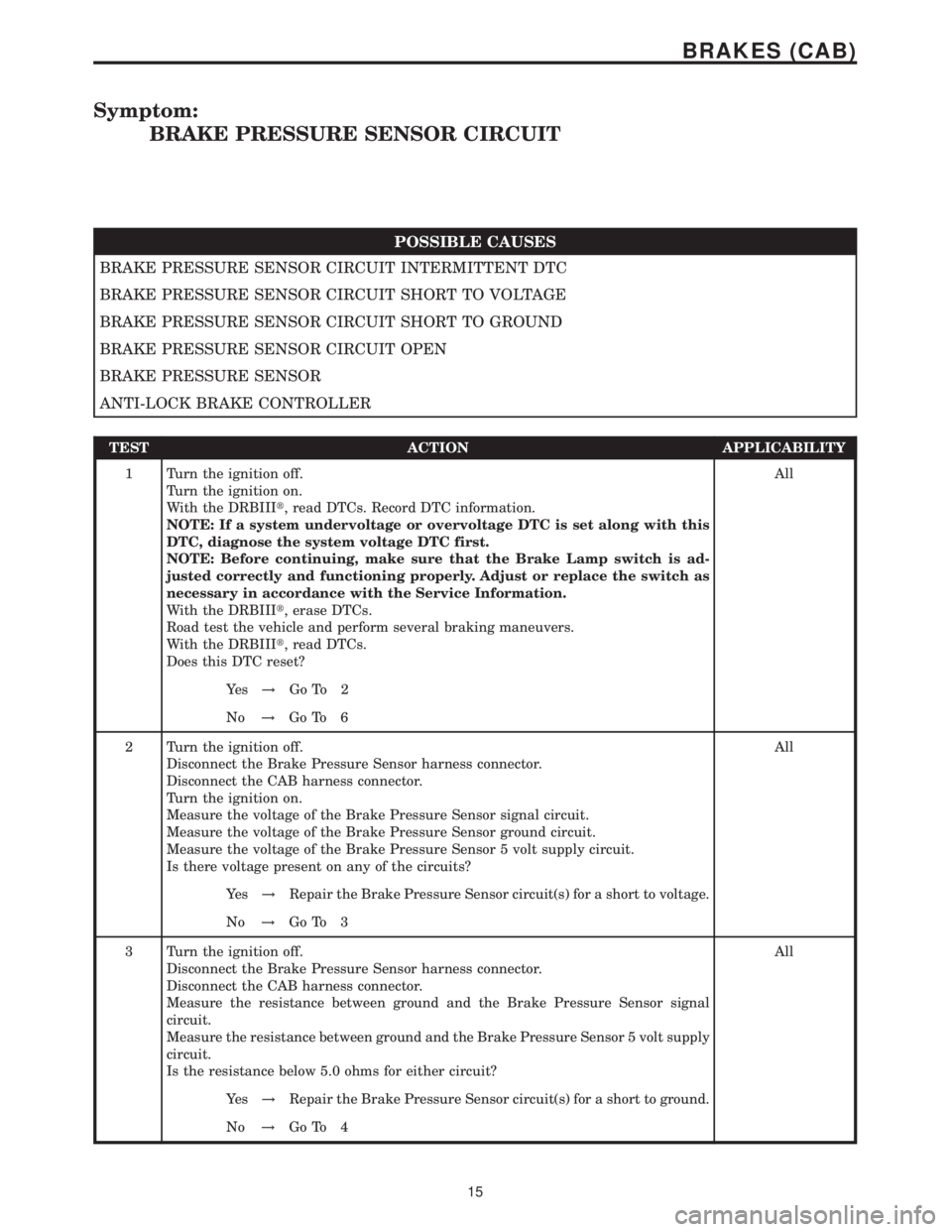
Symptom:
BRAKE PRESSURE SENSOR CIRCUIT
POSSIBLE CAUSES
BRAKE PRESSURE SENSOR CIRCUIT INTERMITTENT DTC
BRAKE PRESSURE SENSOR CIRCUIT SHORT TO VOLTAGE
BRAKE PRESSURE SENSOR CIRCUIT SHORT TO GROUND
BRAKE PRESSURE SENSOR CIRCUIT OPEN
BRAKE PRESSURE SENSOR
ANTI-LOCK BRAKE CONTROLLER
TEST ACTION APPLICABILITY
1 Turn the ignition off.
Turn the ignition on.
With the DRBIIIt, read DTCs. Record DTC information.
NOTE: If a system undervoltage or overvoltage DTC is set along with this
DTC, diagnose the system voltage DTC first.
NOTE: Before continuing, make sure that the Brake Lamp switch is ad-
justed correctly and functioning properly. Adjust or replace the switch as
necessary in accordance with the Service Information.
With the DRBIIIt, erase DTCs.
Road test the vehicle and perform several braking maneuvers.
With the DRBIIIt, read DTCs.
Does this DTC reset?All
Ye s!Go To 2
No!Go To 6
2 Turn the ignition off.
Disconnect the Brake Pressure Sensor harness connector.
Disconnect the CAB harness connector.
Turn the ignition on.
Measure the voltage of the Brake Pressure Sensor signal circuit.
Measure the voltage of the Brake Pressure Sensor ground circuit.
Measure the voltage of the Brake Pressure Sensor 5 volt supply circuit.
Is there voltage present on any of the circuits?All
Ye s!Repair the Brake Pressure Sensor circuit(s) for a short to voltage.
No!Go To 3
3 Turn the ignition off.
Disconnect the Brake Pressure Sensor harness connector.
Disconnect the CAB harness connector.
Measure the resistance between ground and the Brake Pressure Sensor signal
circuit.
Measure the resistance between ground and the Brake Pressure Sensor 5 volt supply
circuit.
Is the resistance below 5.0 ohms for either circuit?All
Ye s!Repair the Brake Pressure Sensor circuit(s) for a short to ground.
No!Go To 4
15
BRAKES (CAB)
Page 337 of 2305
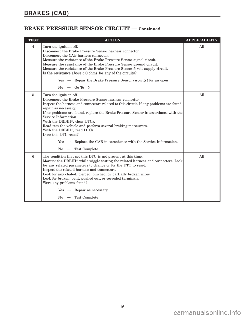
TEST ACTION APPLICABILITY
4 Turn the ignition off.
Disconnect the Brake Pressure Sensor harness connector.
Disconnect the CAB harness connector.
Measure the resistance of the Brake Pressure Sensor signal circuit.
Measure the resistance of the Brake Pressure Sensor ground circuit.
Measure the resistance of the Brake Pressure Sensor 5 volt supply circuit.
Is the resistance above 5.0 ohms for any of the circuits?All
Ye s!Repair the Brake Pressure Sensor circuit(s) for an open
No!Go To 5
5 Turn the ignition off.
Disconnect the Brake Pressure Sensor harness connector.
Inspect the harness and connectors related to this circuit. If any problems are found,
repair as necessary.
If no problems are found, replace the Brake Pressure Sensor in accordance with the
Service Information.
With the DRBIIIt, clear DTCs.
Road test the vehicle and perform several braking maneuvers.
With the DRBIIIt, read DTCs.
Does this DTC reset?All
Ye s!Replace the CAB in accordance with the Service Information.
No!Test Complete.
6 The condition that set this DTC is not present at this time.
Monitor the DRBIIItwhile wiggle testing the related harness and connectors. Look
for any related parameters to change or for the DTC to reset.
Inspect the related harness and connectors.
Look for any chafed, pierced, pinched, or partially broken wires.
Look for broken, bent, pushed out, or corroded terminals.
Were any problems found?All
Ye s!Repair as necessary.
No!Test Complete.
16
BRAKES (CAB)
BRAKE PRESSURE SENSOR CIRCUIT ÐContinued
Page 351 of 2305
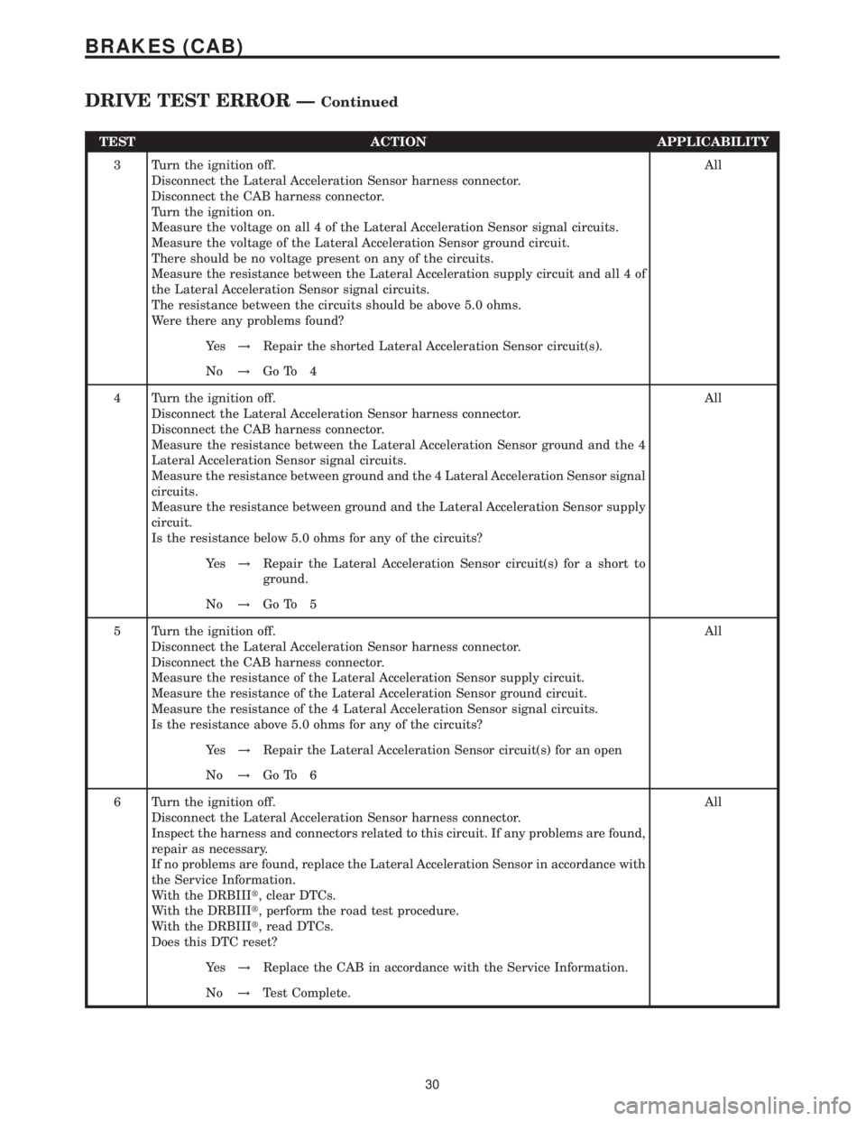
TEST ACTION APPLICABILITY
3 Turn the ignition off.
Disconnect the Lateral Acceleration Sensor harness connector.
Disconnect the CAB harness connector.
Turn the ignition on.
Measure the voltage on all 4 of the Lateral Acceleration Sensor signal circuits.
Measure the voltage of the Lateral Acceleration Sensor ground circuit.
There should be no voltage present on any of the circuits.
Measure the resistance between the Lateral Acceleration supply circuit and all 4 of
the Lateral Acceleration Sensor signal circuits.
The resistance between the circuits should be above 5.0 ohms.
Were there any problems found?All
Ye s!Repair the shorted Lateral Acceleration Sensor circuit(s).
No!Go To 4
4 Turn the ignition off.
Disconnect the Lateral Acceleration Sensor harness connector.
Disconnect the CAB harness connector.
Measure the resistance between the Lateral Acceleration Sensor ground and the 4
Lateral Acceleration Sensor signal circuits.
Measure the resistance between ground and the 4 Lateral Acceleration Sensor signal
circuits.
Measure the resistance between ground and the Lateral Acceleration Sensor supply
circuit.
Is the resistance below 5.0 ohms for any of the circuits?All
Ye s!Repair the Lateral Acceleration Sensor circuit(s) for a short to
ground.
No!Go To 5
5 Turn the ignition off.
Disconnect the Lateral Acceleration Sensor harness connector.
Disconnect the CAB harness connector.
Measure the resistance of the Lateral Acceleration Sensor supply circuit.
Measure the resistance of the Lateral Acceleration Sensor ground circuit.
Measure the resistance of the 4 Lateral Acceleration Sensor signal circuits.
Is the resistance above 5.0 ohms for any of the circuits?All
Ye s!Repair the Lateral Acceleration Sensor circuit(s) for an open
No!Go To 6
6 Turn the ignition off.
Disconnect the Lateral Acceleration Sensor harness connector.
Inspect the harness and connectors related to this circuit. If any problems are found,
repair as necessary.
If no problems are found, replace the Lateral Acceleration Sensor in accordance with
the Service Information.
With the DRBIIIt, clear DTCs.
With the DRBIIIt, perform the road test procedure.
With the DRBIIIt, read DTCs.
Does this DTC reset?All
Ye s!Replace the CAB in accordance with the Service Information.
No!Test Complete.
30
BRAKES (CAB)
DRIVE TEST ERROR ÐContinued
Page 354 of 2305
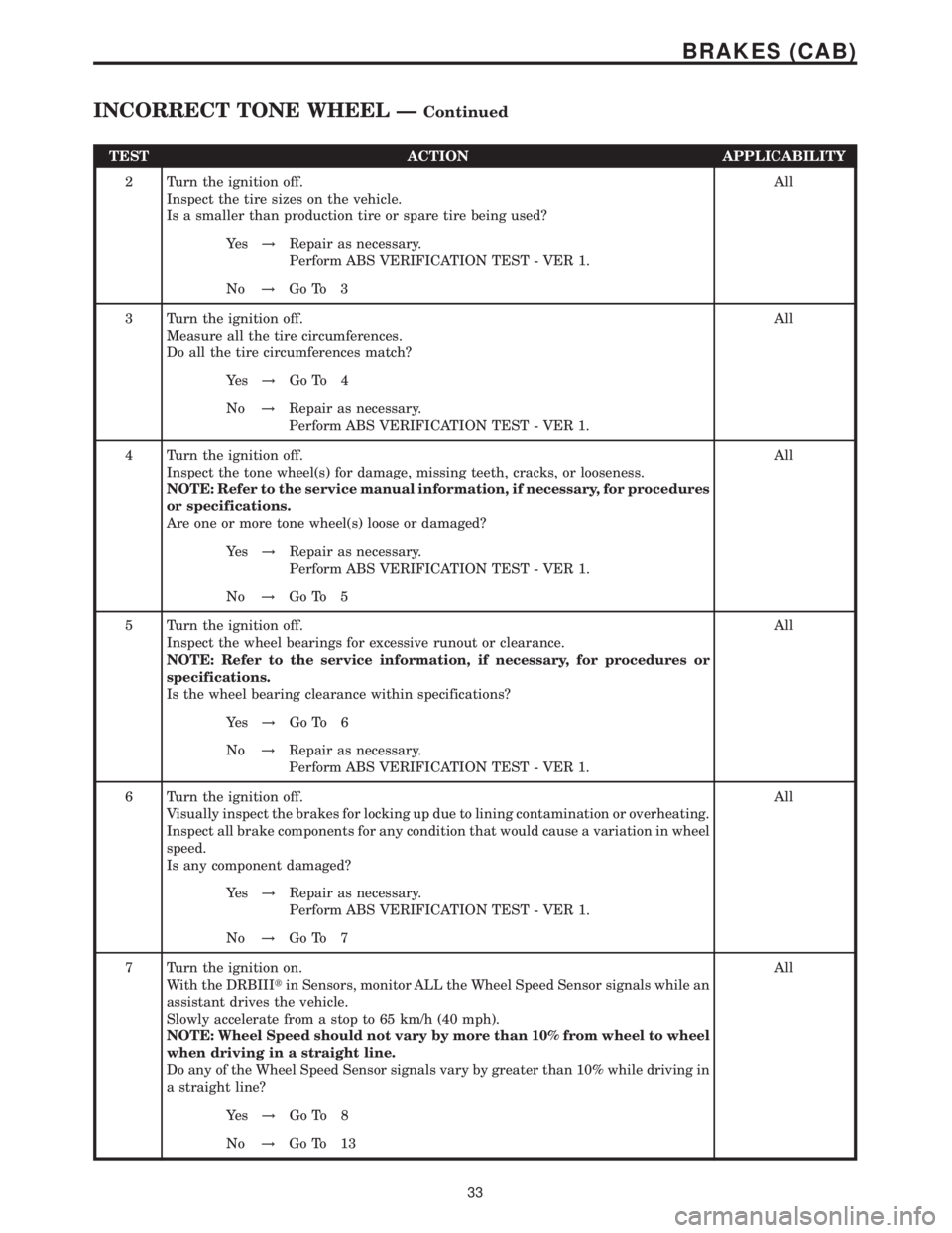
TEST ACTION APPLICABILITY
2 Turn the ignition off.
Inspect the tire sizes on the vehicle.
Is a smaller than production tire or spare tire being used?All
Ye s!Repair as necessary.
Perform ABS VERIFICATION TEST - VER 1.
No!Go To 3
3 Turn the ignition off.
Measure all the tire circumferences.
Do all the tire circumferences match?All
Ye s!Go To 4
No!Repair as necessary.
Perform ABS VERIFICATION TEST - VER 1.
4 Turn the ignition off.
Inspect the tone wheel(s) for damage, missing teeth, cracks, or looseness.
NOTE: Refer to the service manual information, if necessary, for procedures
or specifications.
Are one or more tone wheel(s) loose or damaged?All
Ye s!Repair as necessary.
Perform ABS VERIFICATION TEST - VER 1.
No!Go To 5
5 Turn the ignition off.
Inspect the wheel bearings for excessive runout or clearance.
NOTE: Refer to the service information, if necessary, for procedures or
specifications.
Is the wheel bearing clearance within specifications?All
Ye s!Go To 6
No!Repair as necessary.
Perform ABS VERIFICATION TEST - VER 1.
6 Turn the ignition off.
Visually inspect the brakes for locking up due to lining contamination or overheating.
Inspect all brake components for any condition that would cause a variation in wheel
speed.
Is any component damaged?All
Ye s!Repair as necessary.
Perform ABS VERIFICATION TEST - VER 1.
No!Go To 7
7 Turn the ignition on.
With the DRBIIItin Sensors, monitor ALL the Wheel Speed Sensor signals while an
assistant drives the vehicle.
Slowly accelerate from a stop to 65 km/h (40 mph).
NOTE: Wheel Speed should not vary by more than 10% from wheel to wheel
when driving in a straight line.
Do any of the Wheel Speed Sensor signals vary by greater than 10% while driving in
a straight line?All
Ye s!Go To 8
No!Go To 13
33
BRAKES (CAB)
INCORRECT TONE WHEEL ÐContinued
Page 358 of 2305
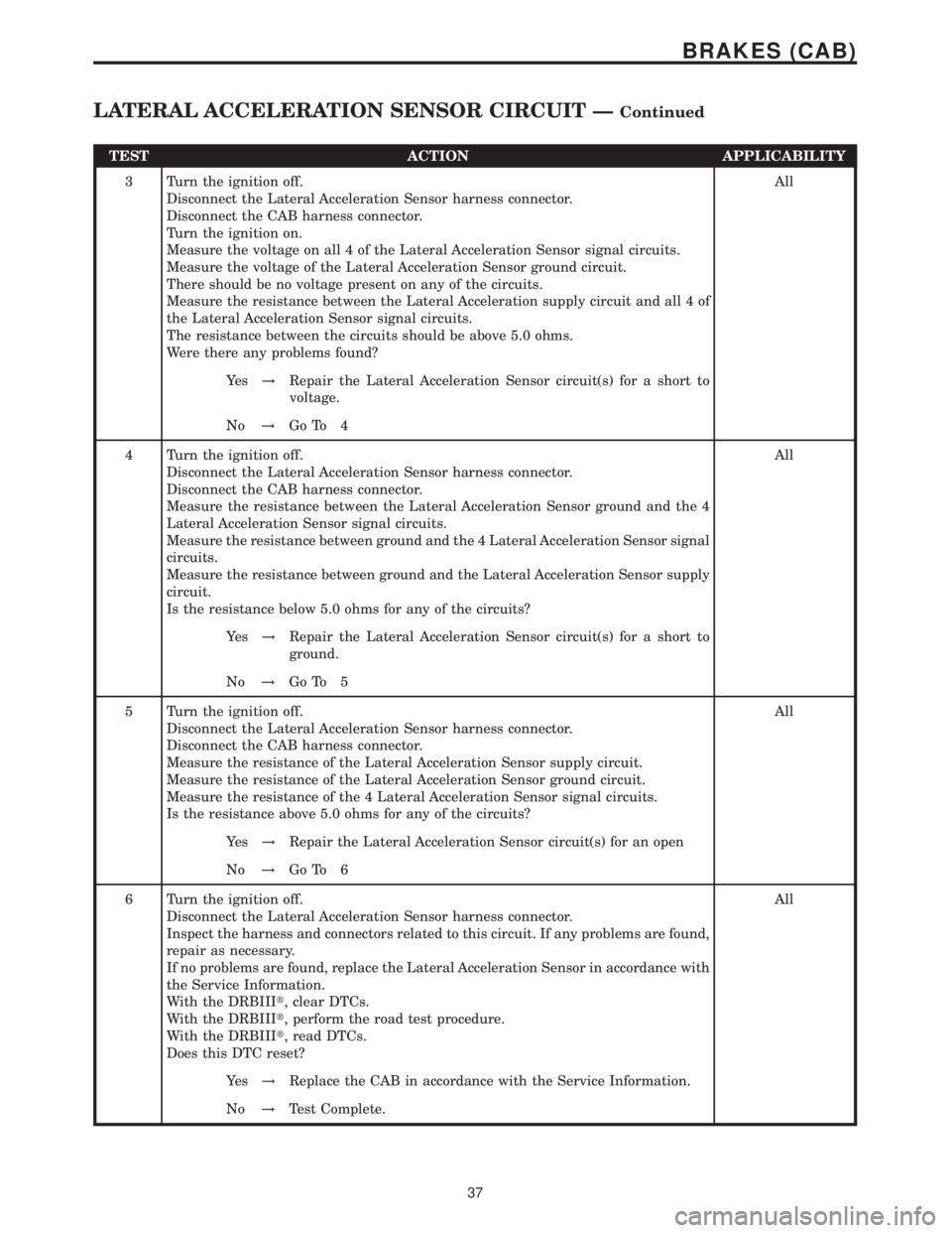
TEST ACTION APPLICABILITY
3 Turn the ignition off.
Disconnect the Lateral Acceleration Sensor harness connector.
Disconnect the CAB harness connector.
Turn the ignition on.
Measure the voltage on all 4 of the Lateral Acceleration Sensor signal circuits.
Measure the voltage of the Lateral Acceleration Sensor ground circuit.
There should be no voltage present on any of the circuits.
Measure the resistance between the Lateral Acceleration supply circuit and all 4 of
the Lateral Acceleration Sensor signal circuits.
The resistance between the circuits should be above 5.0 ohms.
Were there any problems found?All
Ye s!Repair the Lateral Acceleration Sensor circuit(s) for a short to
voltage.
No!Go To 4
4 Turn the ignition off.
Disconnect the Lateral Acceleration Sensor harness connector.
Disconnect the CAB harness connector.
Measure the resistance between the Lateral Acceleration Sensor ground and the 4
Lateral Acceleration Sensor signal circuits.
Measure the resistance between ground and the 4 Lateral Acceleration Sensor signal
circuits.
Measure the resistance between ground and the Lateral Acceleration Sensor supply
circuit.
Is the resistance below 5.0 ohms for any of the circuits?All
Ye s!Repair the Lateral Acceleration Sensor circuit(s) for a short to
ground.
No!Go To 5
5 Turn the ignition off.
Disconnect the Lateral Acceleration Sensor harness connector.
Disconnect the CAB harness connector.
Measure the resistance of the Lateral Acceleration Sensor supply circuit.
Measure the resistance of the Lateral Acceleration Sensor ground circuit.
Measure the resistance of the 4 Lateral Acceleration Sensor signal circuits.
Is the resistance above 5.0 ohms for any of the circuits?All
Ye s!Repair the Lateral Acceleration Sensor circuit(s) for an open
No!Go To 6
6 Turn the ignition off.
Disconnect the Lateral Acceleration Sensor harness connector.
Inspect the harness and connectors related to this circuit. If any problems are found,
repair as necessary.
If no problems are found, replace the Lateral Acceleration Sensor in accordance with
the Service Information.
With the DRBIIIt, clear DTCs.
With the DRBIIIt, perform the road test procedure.
With the DRBIIIt, read DTCs.
Does this DTC reset?All
Ye s!Replace the CAB in accordance with the Service Information.
No!Test Complete.
37
BRAKES (CAB)
LATERAL ACCELERATION SENSOR CIRCUIT ÐContinued
Page 367 of 2305
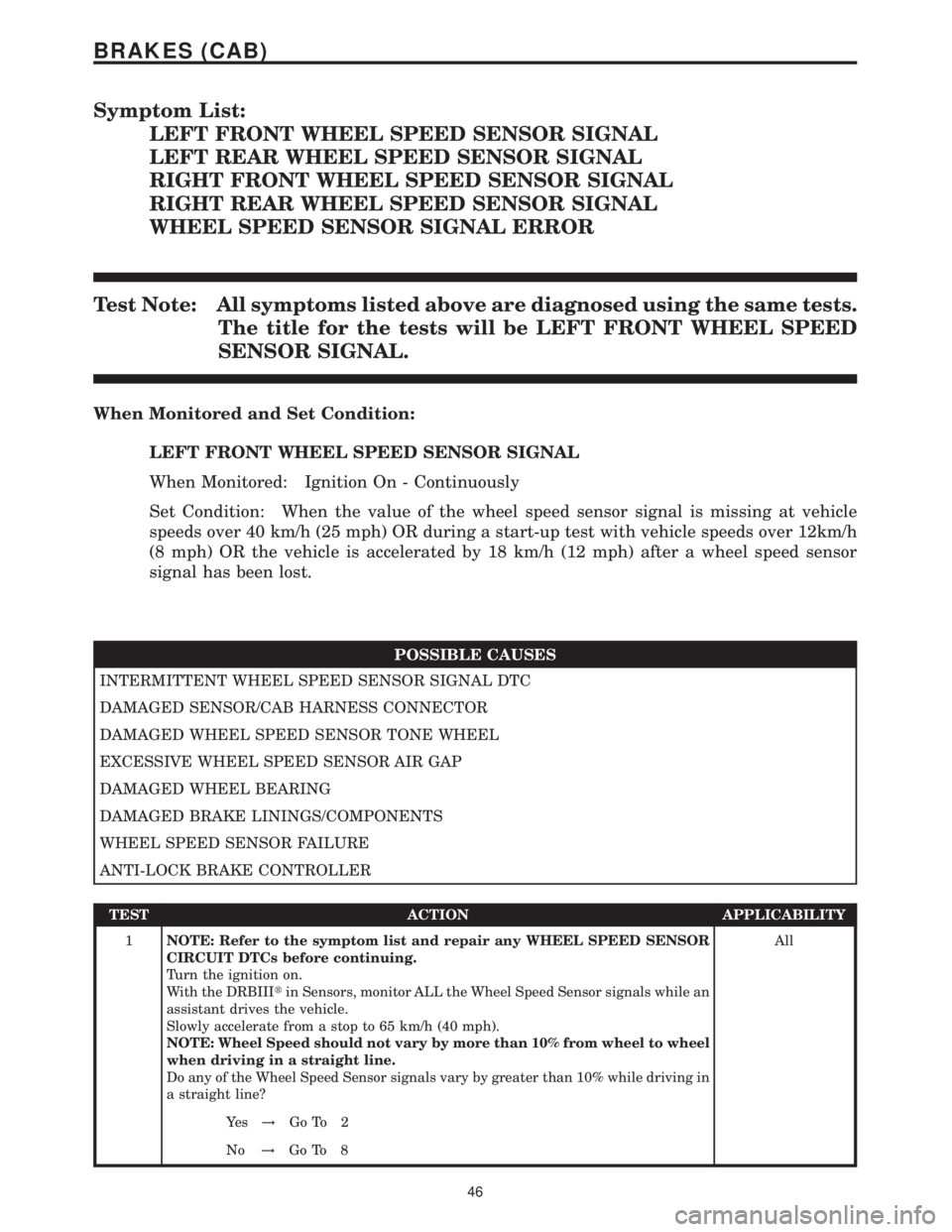
Symptom List:
LEFT FRONT WHEEL SPEED SENSOR SIGNAL
LEFT REAR WHEEL SPEED SENSOR SIGNAL
RIGHT FRONT WHEEL SPEED SENSOR SIGNAL
RIGHT REAR WHEEL SPEED SENSOR SIGNAL
WHEEL SPEED SENSOR SIGNAL ERROR
Test Note: All symptoms listed above are diagnosed using the same tests.
The title for the tests will be LEFT FRONT WHEEL SPEED
SENSOR SIGNAL.
When Monitored and Set Condition:
LEFT FRONT WHEEL SPEED SENSOR SIGNAL
When Monitored: Ignition On - Continuously
Set Condition: When the value of the wheel speed sensor signal is missing at vehicle
speeds over 40 km/h (25 mph) OR during a start-up test with vehicle speeds over 12km/h
(8 mph) OR the vehicle is accelerated by 18 km/h (12 mph) after a wheel speed sensor
signal has been lost.
POSSIBLE CAUSES
INTERMITTENT WHEEL SPEED SENSOR SIGNAL DTC
DAMAGED SENSOR/CAB HARNESS CONNECTOR
DAMAGED WHEEL SPEED SENSOR TONE WHEEL
EXCESSIVE WHEEL SPEED SENSOR AIR GAP
DAMAGED WHEEL BEARING
DAMAGED BRAKE LININGS/COMPONENTS
WHEEL SPEED SENSOR FAILURE
ANTI-LOCK BRAKE CONTROLLER
TEST ACTION APPLICABILITY
1NOTE: Refer to the symptom list and repair any WHEEL SPEED SENSOR
CIRCUIT DTCs before continuing.
Turn the ignition on.
With the DRBIIItin Sensors, monitor ALL the Wheel Speed Sensor signals while an
assistant drives the vehicle.
Slowly accelerate from a stop to 65 km/h (40 mph).
NOTE: Wheel Speed should not vary by more than 10% from wheel to wheel
when driving in a straight line.
Do any of the Wheel Speed Sensor signals vary by greater than 10% while driving in
a straight line?All
Ye s!Go To 2
No!Go To 8
46
BRAKES (CAB)