check oil MERCEDES-BENZ SPRINTER 2006 Workshop Manual
[x] Cancel search | Manufacturer: MERCEDES-BENZ, Model Year: 2006, Model line: SPRINTER, Model: MERCEDES-BENZ SPRINTER 2006Pages: 2305, PDF Size: 48.12 MB
Page 1585 of 2305
(11) Install the torque converter access plate. Refer
to (Refer to 21 - TRANSMISSION/TRANSAXLE/AU-
TOMATIC - NAG1 - INSTALLATION) for correct
sequence and torque specification.
(12) Install the transmission cooler lines to trans-
mission. (Refer to 21 - TRANSMISSION/TRANS-
AXLE/AUTOMATIC - NAG1 - INSTALLATION) for
correct sequence and torque specification.
(13) Connect the engine valley drain hose to the
transmission (Fig. 5).
(14) Install transmission electrical connector and
shifter hardware. Refer to (Refer to 21 - TRANSMIS-
SION/TRANSAXLE/AUTOMATIC - NAG1 - INSTAL-
LATION) for correct sequence and torque
specification.
(15) Install the steering gear and tighten in two
stages. 25 N´m (18.5 lbs. ft.), then 45 N´m (33 lbs. ft.)
plus 90É.
(16) Install the starter.
(17) Connect the ground strap (left side).
(18) Align and install the exhaust and bracket
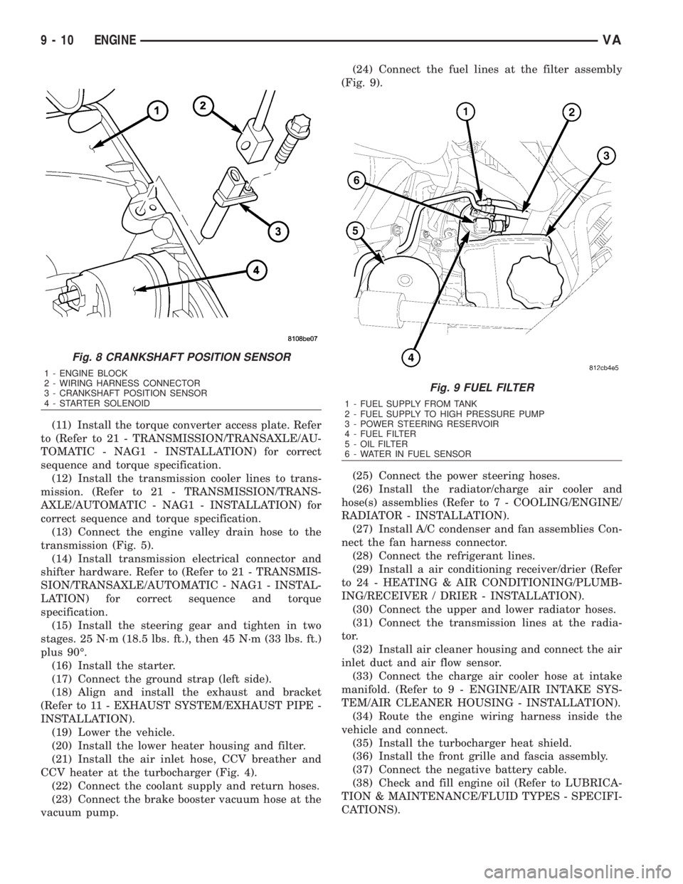
(Refer to 11 - EXHAUST SYSTEM/EXHAUST PIPE -
INSTALLATION).
(19) Lower the vehicle.
(20) Install the lower heater housing and filter.
(21) Install the air inlet hose, CCV breather and
CCV heater at the turbocharger (Fig. 4).
(22) Connect the coolant supply and return hoses.
(23) Connect the brake booster vacuum hose at the
vacuum pump.(24) Connect the fuel lines at the filter assembly
(Fig. 9).
(25) Connect the power steering hoses.
(26) Install the radiator/charge air cooler and
hose(s) assemblies (Refer to 7 - COOLING/ENGINE/
RADIATOR - INSTALLATION).
(27) Install A/C condenser and fan assemblies Con-
nect the fan harness connector.
(28) Connect the refrigerant lines.
(29) Install a air conditioning receiver/drier (Refer
to 24 - HEATING & AIR CONDITIONING/PLUMB-
ING/RECEIVER / DRIER - INSTALLATION).
(30) Connect the upper and lower radiator hoses.
(31) Connect the transmission lines at the radia-
tor.
(32) Install air cleaner housing and connect the air
inlet duct and air flow sensor.
(33) Connect the charge air cooler hose at intake
manifold. (Refer to 9 - ENGINE/AIR INTAKE SYS-
TEM/AIR CLEANER HOUSING - INSTALLATION).
(34) Route the engine wiring harness inside the
vehicle and connect.
(35) Install the turbocharger heat shield.
(36) Install the front grille and fascia assembly.
(37) Connect the negative battery cable.
(38) Check and fill engine oil (Refer to LUBRICA-
TION & MAINTENANCE/FLUID TYPES - SPECIFI-
CATIONS).
Fig. 8 CRANKSHAFT POSITION SENSOR
1 - ENGINE BLOCK
2 - WIRING HARNESS CONNECTOR
3 - CRANKSHAFT POSITION SENSOR
4 - STARTER SOLENOID
Fig. 9 FUEL FILTER
1 - FUEL SUPPLY FROM TANK
2 - FUEL SUPPLY TO HIGH PRESSURE PUMP
3 - POWER STEERING RESERVOIR
4 - FUEL FILTER
5 - OIL FILTER
6 - WATER IN FUEL SENSOR
9 - 10 ENGINEVA
Page 1586 of 2305
(39) Fill cooling system to proper level with the
appropriate coolant.
(40) Evacuate and recharge air conditioning.
(41) Check and refill all ancillary system fluid lev-
els.(42) Start engine and inspect for leaks (Refer to 14
- FUEL SYSTEM - WARNING).
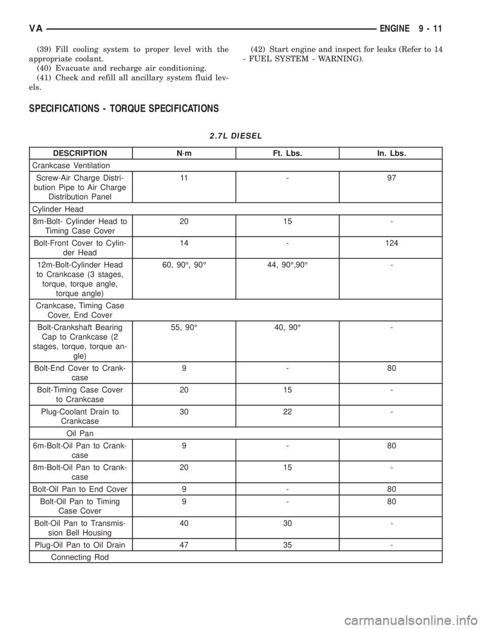
SPECIFICATIONS - TORQUE SPECIFICATIONS
2.7L DIESEL
DESCRIPTION N´m Ft. Lbs. In. Lbs.
Crankcase Ventilation
Screw-Air Charge Distri-
bution Pipe to Air Charge
Distribution Panel11 - 9 7
Cylinder Head
8m-Bolt- Cylinder Head to
Timing Case Cover20 15 -
Bolt-Front Cover to Cylin-
der Head14 - 124
12m-Bolt-Cylinder Head
to Crankcase (3 stages,
torque, torque angle,
torque angle)60, 90É, 90É 44, 90É,90É -
Crankcase, Timing Case
Cover, End Cover
Bolt-Crankshaft Bearing
Cap to Crankcase (2
stages, torque, torque an-
gle)55, 90É 40, 90É -
Bolt-End Cover to Crank-
case9-80
Bolt-Timing Case Cover
to Crankcase20 15 -
Plug-Coolant Drain to
Crankcase30 22 -
Oil Pan
6m-Bolt-Oil Pan to Crank-
case9-80
8m-Bolt-Oil Pan to Crank-
case20 15 -
Bolt-Oil Pan to End Cover 9 - 80
Bolt-Oil Pan to Timing
Case Cover9-80
Bolt-Oil Pan to Transmis-
sion Bell Housing40 30 -
Plug-Oil Pan to Oil Drain 47 35 -
Connecting Rod
VAENGINE 9 - 11
Page 1603 of 2305
INSTALLATION - CYLINDER HEAD FRONT
COVER
NOTE: Thoroughly clean all mating surfaces with
appropriate solvents to assure that no grease or oil
is present during reassembly.
NOTE: Dowel pins are used as a guide during
assembly and must remain in the proper position to
assure a good sealing surface.
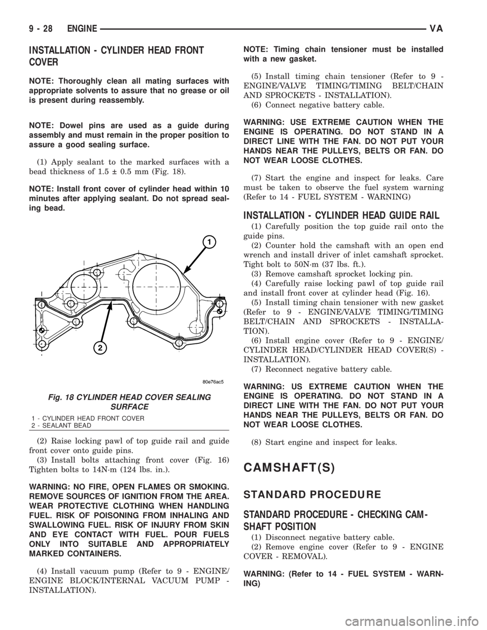
(1) Apply sealant to the marked surfaces with a
bead thickness of 1.5 0.5 mm (Fig. 18).
NOTE: Install front cover of cylinder head within 10
minutes after applying sealant. Do not spread seal-
ing bead.
(2) Raise locking pawl of top guide rail and guide
front cover onto guide pins.
(3) Install bolts attaching front cover (Fig. 16)
Tighten bolts to 14N´m (124 lbs. in.).
WARNING: NO FIRE, OPEN FLAMES OR SMOKING.
REMOVE SOURCES OF IGNITION FROM THE AREA.
WEAR PROTECTIVE CLOTHING WHEN HANDLING
FUEL. RISK OF POISONING FROM INHALING AND
SWALLOWING FUEL. RISK OF INJURY FROM SKIN
AND EYE CONTACT WITH FUEL. POUR FUELS
ONLY INTO SUITABLE AND APPROPRIATELY
MARKED CONTAINERS.
(4) Install vacuum pump (Refer to 9 - ENGINE/
ENGINE BLOCK/INTERNAL VACUUM PUMP -
INSTALLATION).NOTE: Timing chain tensioner must be installed
with a new gasket.
(5) Install timing chain tensioner (Refer to 9 -
ENGINE/VALVE TIMING/TIMING BELT/CHAIN
AND SPROCKETS - INSTALLATION).
(6) Connect negative battery cable.
WARNING: USE EXTREME CAUTION WHEN THE
ENGINE IS OPERATING. DO NOT STAND IN A
DIRECT LINE WITH THE FAN. DO NOT PUT YOUR
HANDS NEAR THE PULLEYS, BELTS OR FAN. DO
NOT WEAR LOOSE CLOTHES.
(7) Start the engine and inspect for leaks. Care
must be taken to observe the fuel system warning
(Refer to 14 - FUEL SYSTEM - WARNING)
INSTALLATION - CYLINDER HEAD GUIDE RAIL
(1) Carefully position the top guide rail onto the
guide pins.
(2) Counter hold the camshaft with an open end
wrench and install driver of inlet camshaft sprocket.
Tight bolt to 50N´m (37 lbs. ft.).
(3) Remove camshaft sprocket locking pin.
(4) Carefully raise locking pawl of top guide rail
and install front cover at cylinder head (Fig. 16).
(5) Install timing chain tensioner with new gasket
(Refer to 9 - ENGINE/VALVE TIMING/TIMING
BELT/CHAIN AND SPROCKETS - INSTALLA-
TION).
(6) Install engine cover (Refer to 9 - ENGINE/
CYLINDER HEAD/CYLINDER HEAD COVER(S) -
INSTALLATION).
(7) Reconnect negative battery cable.
WARNING: US EXTREME CAUTION WHEN THE
ENGINE IS OPERATING. DO NOT STAND IN A
DIRECT LINE WITH THE FAN. DO NOT PUT YOUR
HANDS NEAR THE PULLEYS, BELTS OR FAN. DO
NOT WEAR LOOSE CLOTHES.
(8) Start engine and inspect for leaks.
CAMSHAFT(S)
STANDARD PROCEDURE
STANDARD PROCEDURE - CHECKING CAM-
SHAFT POSITION
(1) Disconnect negative battery cable.
(2) Remove engine cover (Refer to 9 - ENGINE
COVER - REMOVAL).
WARNING: (Refer to 14 - FUEL SYSTEM - WARN-
ING)
Fig. 18 CYLINDER HEAD COVER SEALING
SURFACE
1 - CYLINDER HEAD FRONT COVER
2 - SEALANT BEAD
9 - 28 ENGINEVA
Page 1605 of 2305
WARNING: USE EXTREME CAUTION WHEN THE
ENGINE IS OPERATING. DO NOT STAND IN A
DIRECT LINE WITH THE FAN. DO NOT PUT YOUR
HANDS NEAR THE PULLEYS, BELTS OR FAN. DO
NO WEAR LOOSE CLOTHING.
(11) Start the engine and inspect for leaks.
STANDARD PROCEDURE - INSPECTING TAP-
PET CLEARANCE
(1) Check engine oil level, adjust as necessary.
(2) Warm engine to operating temperature
(approx. 80ÉC, 176ÉF).
(3) Remove the cylinder head cover (Refer to 9 -
ENGINE/CYLINDER HEAD/CYLINDER HEAD
COVER(S) - REMOVAL).
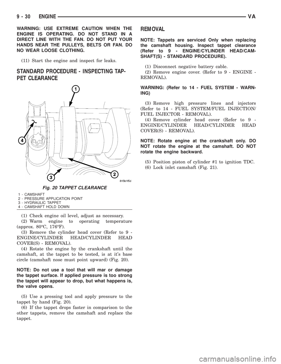
(4) Rotate the engine by the crankshaft until the
camshaft, at the tappet to be tested, is at it's base
circle (camshaft nose must point upward) (Fig. 20).
NOTE: Do not use a tool that will mar or damage
the tappet surface. If applied pressure is too strong
the tappet will appear to drop, but what happens is,
the valve opens.
(5) Use a pressing tool and apply pressure to the
tappet by hand (Fig. 20).
(6) If the tappet drops faster in comparison to the
other tappets, remove the camshaft and replace the
tappet.
REMOVAL
NOTE: Tappets are serviced Only when replacing
the camshaft housing. Inspect tappet clearance
(Refer to 9 - ENGINE/CYLINDER HEAD/CAM-
SHAFT(S) - STANDARD PROCEDURE).
(1) Disconnect negative battery cable.
(2) Remove engine cover. (Refer to 9 - ENGINE -
REMOVAL).
WARNING: (Refer to 14 - FUEL SYSTEM - WARN-
ING)
(3) Remove high pressure lines and injectors
(Refer to 14 - FUEL SYSTEM/FUEL INJECTION/
FUEL INJECTOR - REMOVAL).
(4) Remove cylinder head cover (Refer to 9 -
ENGINE/CYLINDER HEAD/CYLINDER HEAD
COVER(S) - REMOVAL).
NOTE: Rotate engine at the crankshaft only. DO
NOT rotate the engine at the camshaft. DO NOT
rotate the engine backward.
(5) Position piston of cylinder #1 to ignition TDC.
(6) Lock inlet camshaft (Fig. 21).
Fig. 20 TAPPET CLEARANCE
1 - CAMSHAFT
2 - PRESSURE APPLICATION POINT
3 - HYDRAULIC TAPPET
4 - CAMSHAFT HOLD DOWN
9 - 30 ENGINEVA
Page 1612 of 2305
NOTE: Using valve service tools #9307, screw
retaining fork into threaded edge of cylinder head
and position thrust piece vertically at the top of
each exhaust valve spring retainer. Use the cam
bearing cap threaded holes to position service tool
for installation of intake valve spring retainers.
NOTE: Ensure that the valve keepers are seated
properly.
(9) Compress valve and install valve collates (Fig.
26).
CAUTION: Make sure the crankshaft lock is in posi-
tion and properly secured for each cylinder being
serviced. Failure to do so may result in damage to
the vehicle or personal injury.
(10) Repeat procedure for each cylinder as neces-
sary.
(11) Remove special tooling from cylinder head.
(12) Position piston of #1 cylinder to ignition TDC.
(13) Install camshafts and check basic position
(Refer to 9 - ENGINE/CYLINDER HEAD/CAM-
SHAFT(S) - INSTALLATION).
(14) Install top guide rail (Refer to 9 - ENGINE/
CYLINDER HEAD - INSTALLATION).
(15) Install front cover at cylinder head (Refer to 9
- ENGINE/CYLINDER HEAD - INSTALLATION).
(16) Install timing chain tensioner with new gas-
ket (Refer to 9 - ENGINE/VALVE TIMING/TIMING
BELT/CHAIN AND SPROCKETS - INSTALLATION)
(17) Install cylinder head cover (Refer to 9 -
ENGINE/CYLINDER HEAD/CYLINDER HEAD
COVER(S) - INSTALLATION).
WARNING: (Refer to 14 - FUEL SYSTEM - WARN-
ING).
(18) Install injectors (Refer to 14 - FUEL SYS-
TEM/FUEL INJECTION/FUEL INJECTOR -
INSTALLATION).
(19) Reconnect negative battery cable.
(20) Start the engine, allow to warm, turn engine
off and inspect for leaks. Care must be taken to
observe the fuel system warning (Refer to 14 - FUEL
SYSTEM - WARNING)
(21) Install engine cover (Refer to 9 - ENGINE
COVER - INSTALLATION).
INSTALLATION - VALVES
WARNING: Valves must be kept in their original
positions in cylinder head. Failure to do so will
result in engine damage.NOTE: Inspect all valves, springs and retainers for
wear or damage. Replace as necessary.
(1) Install valves in their original position in the
cylinder head.
(2) Install lower valve spring retainer.
(3) Install valve stem seal.
(4) Install valve spring.
(5) Install valve spring retainer.
NOTE: Using tool, screw retaining fork into
threaded edge of cylinder head and position thrust
piece vertically at the top of each valve spring
retainer.
NOTE: Ensure that the valve keepers are seated
properly.
(6) Using a suitable valve spring compressor, com-
press valve spring and install valve keepers.
(7) Repeat steps 3 through 7 for each valve as nec-
essary.
(8) Remove valve assembly from cylinder head.
(9) Install cylinder head on engine block (Refer to
9 - ENGINE/CYLINDER HEAD - INSTALLATION).
(10) Install glow plugs (Refer to 8 - ELECTRICAL/
IGNITION CONTROL/GLOW PLUG - INSTALLA-
TION).
(11) Connect negative battery cable.
WARNING: US EXTREME CAUTION WHEN THE
ENGINE IS IN OPERATION. DO NOT STAND IN A
DIRECT LINE WITH THE FAN. DO NOT PUT YOUR
HANDS NEAR THE PULLEYS, BELTS OR FAN. DO
NOT WEAR LOOSE CLOTHING.
(12) Start engine and check for leaks. Care must
be taken to observe the fuel system warning (Refer to
14 - FUEL SYSTEM - WARNING)
(13) Install engine cover (Refer to 9 - ENGINE
COVER - INSTALLATION).
ENGINE BLOCK
STANDARD PROCEDURE
STANDARD PROCEDURE - REPLACING ENGINE
CORE AND OIL GALLERY PLUGS
Using a blunt tool such as a drift and a hammer,
strike the bottom edge of the cup plug. With the cup
plug rotated, grasp firmly with pliers or other suit-
able tool and remove plug (Fig. 30).
VAENGINE 9 - 37
Page 1616 of 2305
CAUTION: Oil thread and head contact surfaces of
bolts that retain the crankshaft bearing caps;
tighten bolts from inside to outside, beginning at
the fit bearing. Rotate crankshaft to check clear-
ance.
(1) Install crankshaft.
CAUTION: The crankshaft bearing caps are num-
bered consecutively, beginning with the first crank-
shaft bearing cap at the front of the engine.
Attention must be paid to the way the crankshaft
bearing caps fit. If correctly installed, the lug, or
raised boss, on the crankshaft bearing cap is point-
ing to the left when viewed in the direction of travel
(intake side).
(2) Install the crankshaft bearing caps. Tighten
bolts in two stages. 55N´m (40.5 lbs. ft.), then 90É.
(3) Install the pistons (Refer to 9 - ENGINE/EN-
GINE BLOCK/PISTON & CONNECTING ROD -
INSTALLATION).
(4) Install the end cover (Refer to 9 - ENGINE/EN-
GINE BLOCK/CRANKSHAFT OIL SEAL - REAR -
INSTALLATION).
(5) Install the timing case cover (Refer to 9 -
ENGINE/VALVE TIMING/TIMING BELT / CHAIN
COVER(S) - INSTALLATION).
(6) Install the engine (Refer to 9 - ENGINE -
INSTALLATION).
(7) Fill the crankcase with the correct engine oil,
to the proper level. Refer to the owners manual for
specifications.
(8) Fill the cooling system with the proper coolant,
to the proper level (Refer to 7 - COOLING/ENGINE/
COOLANT - STANDARD PROCEDURE).
(9) Connect the negative battery cable.
WARNING: USE EXTREME CAUTION WHEN THE
ENGINE IS OPERATING. DO NOT STAND IN A
DIRECT LINE WITH THE FAN. DO NOT PUT YOUR
HANDS NEAR THE PULLEYS, BELTS, OR FAN. DO
NOT WEAR LOOSE CLOTHES.
(10) Start engine and inspect for leaks. Care must
be taken to observe the fuel system warning (Refer to
14 - FUEL SYSTEM - WARNING).
CRANKSHAFT OIL SEAL -
REAR
REMOVAL
This must be done with the transmission removed
from the vehicle.
(1) Disconnect the negative battery cable.
(2) Raise and support the vehicle.
(3) Drain the engine oil.NOTE: Loosen all of the oil pan bolts to assure that
the oil pan gasket is not damaged when removing
the rear main oil seal and end cover assembly.
NOTE: Inspect the oil pan gasket for damage. If the
oil pan gasket is damaged, remove the oil pan and
replace the oil pan gasket.
(4) Loosen the oil pan bolts.
(5) Remove the flywheel.
CAUTION: Care must be taken when removing the
rear main seal and adaptor assembly. Failure to do
so will result in damage to the oil pan gasket.
(6) Remove the rear main seal/adaptor retaining
bolts and carefully pry the adaptor from the crank-
case at the adaptor shoulders (Fig. 33).
VAENGINE 9 - 41
Page 1626 of 2305
(9) Clean and inspect the connecting rod bolts.
CAUTION: Assure that the correct top and bottom
connecting rod bearings shells are used in accor-
dance with the markings.
CAUTION: The anti-twist locks of the connecting
rod bearing shells must be located in the slots of
the connecting rod bearing caps.
(10) Insert connecting rod bearing shell into con-
necting rod bearing cap.
CAUTION: The markings on the connecting rod and
connecting rod cap must be lined up.
(11) Install connecting rod bearing cap. Tighten
bolts in 3 stages, 5N´m (44 lbs in), 25N´m (221 lbs
in), 90É.
(12) Rotate crankshaft fully and check the clear-
ance.(13) Install oil pump (Refer to 9 - ENGINE/LU-
BRICATION/OIL PUMP - INSTALLATION).
(14) Install engine oil pan and oil pan drain plug
(Refer to 9 - ENGINE/LUBRICATION/OIL PAN -
INSTALLATION).
CAUTION: Install a cylinder head gasket of standard
thickness or a cylinder head gasket of repair thick-
ness depending on piston protrusion.
(15) Measure piston protrusion (Refer to 9 -
ENGINE/ENGINE BLOCK - STANDARD PROCE-
DURE).
(16) Install cylinder head (Refer to 9 - ENGINE/
CYLINDER HEAD - INSTALLATION).
(17) Install engine (Refer to 9 - ENGINE -
INSTALLATION).
(18) Fill the crankcase with correct engine oil, to
proper level. Refer to owners manual for specifica-
tions.
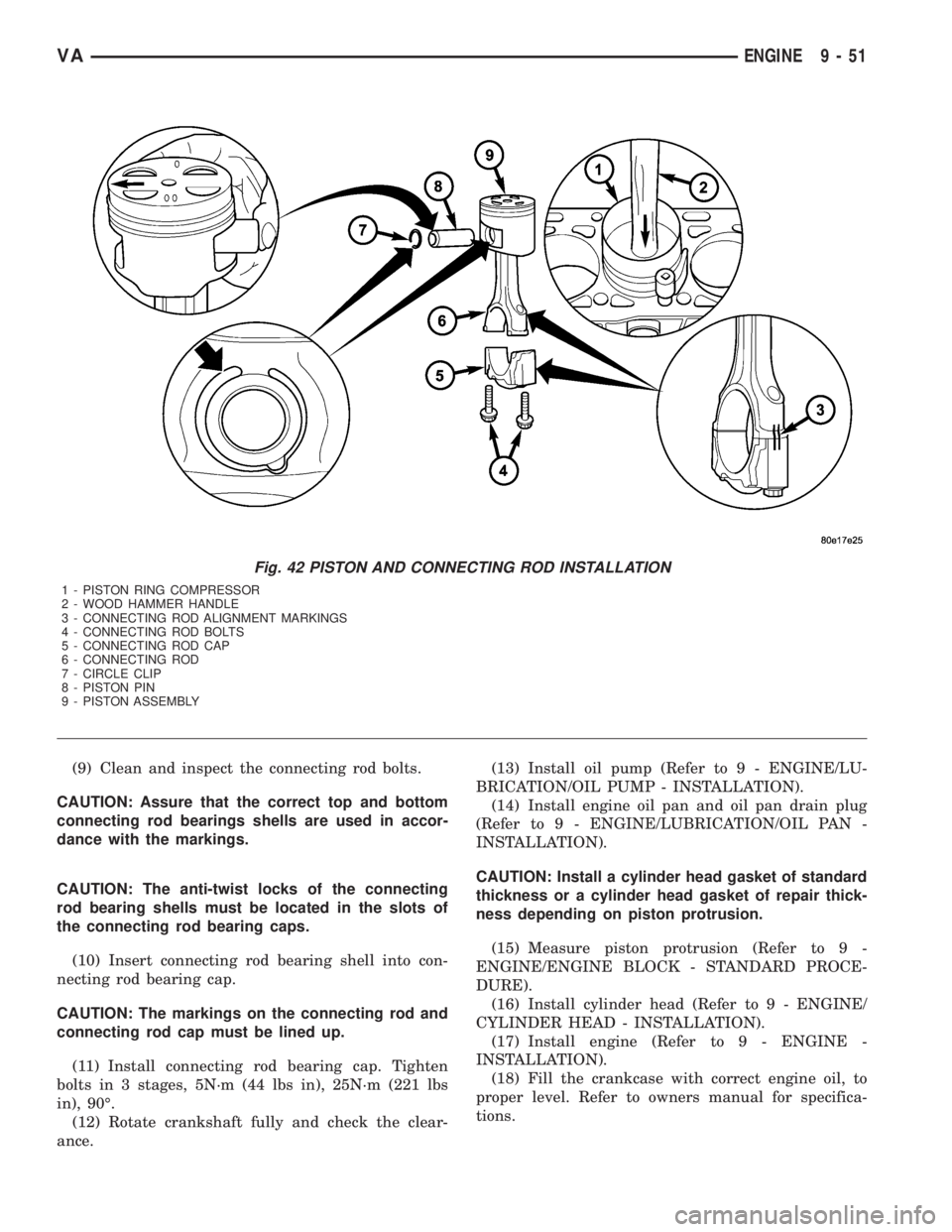
Fig. 42 PISTON AND CONNECTING ROD INSTALLATION
1 - PISTON RING COMPRESSOR
2 - WOOD HAMMER HANDLE
3 - CONNECTING ROD ALIGNMENT MARKINGS
4 - CONNECTING ROD BOLTS
5 - CONNECTING ROD CAP
6 - CONNECTING ROD
7 - CIRCLE CLIP
8 - PISTON PIN
9 - PISTON ASSEMBLY
VAENGINE 9 - 51
Page 1632 of 2305
INSTALLATION
(1) Clean all sealing surfaces.
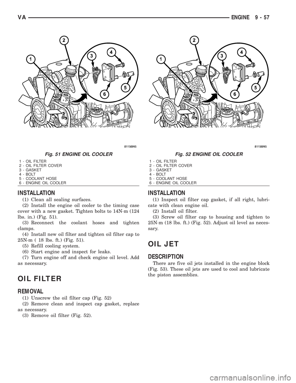
(2) Install the engine oil cooler to the timing case
cover with a new gasket. Tighten bolts to 14N´m (124
lbs. in.) (Fig. 51).
(3) Reconnect the coolant hoses and tighten
clamps.
(4) Install new oil filter and tighten oil filter cap to
25N´m ( 18 lbs. ft.) (Fig. 51).
(5) Refill cooling system.
(6) Start engine and inspect for leaks.
(7) Turn engine off and check engine oil level. Add
as necessary.
OIL FILTER
REMOVAL
(1) Unscrew the oil filter cap (Fig. 52)
(2) Remove clean and inspect cap gasket, replace
as necessary.
(3) Remove oil filter (Fig. 52).
INSTALLATION
(1) Inspect oil filter cap gasket, if all right, lubri-
cate with clean engine oil.
(2) Install oil filter.
(3) Screw oil filter cap to housing and tighten to
25N´m (18 lbs. ft.) (Fig. 52). Adjust oil level as neces-
sary.
OIL JET
DESCRIPTION
There are five oil jets installed in the engine block
(Fig. 53). These oil jets are used to cool and lubricate
the piston assemblies.
Fig. 51 ENGINE OIL COOLER
1 - OIL FILTER
2 - OIL FILTER COVER
3 - GASKET
4 - BOLT
5 - COOLANT HOSE
6 - ENGINE OIL COOLER
Fig. 52 ENGINE OIL COOLER
1 - OIL FILTER
2 - OIL FILTER COVER
3 - GASKET
4 - BOLT
5 - COOLANT HOSE
6 - ENGINE OIL COOLER
VAENGINE 9 - 57
Page 1662 of 2305
OPERATION
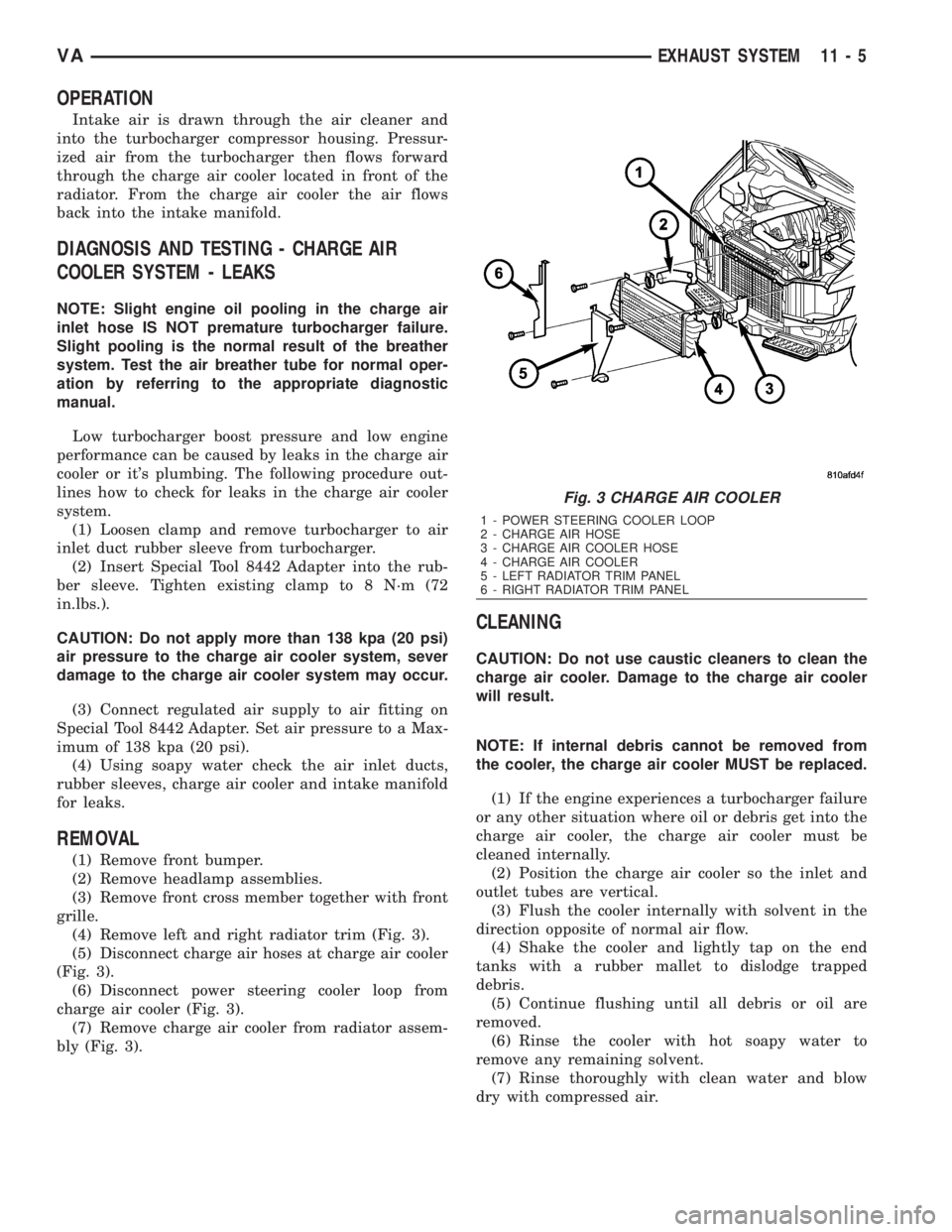
Intake air is drawn through the air cleaner and
into the turbocharger compressor housing. Pressur-
ized air from the turbocharger then flows forward
through the charge air cooler located in front of the
radiator. From the charge air cooler the air flows
back into the intake manifold.
DIAGNOSIS AND TESTING - CHARGE AIR
COOLER SYSTEM - LEAKS
NOTE: Slight engine oil pooling in the charge air
inlet hose IS NOT premature turbocharger failure.
Slight pooling is the normal result of the breather
system. Test the air breather tube for normal oper-
ation by referring to the appropriate diagnostic
manual.
Low turbocharger boost pressure and low engine
performance can be caused by leaks in the charge air
cooler or it's plumbing. The following procedure out-
lines how to check for leaks in the charge air cooler
system.
(1) Loosen clamp and remove turbocharger to air
inlet duct rubber sleeve from turbocharger.
(2) Insert Special Tool 8442 Adapter into the rub-
ber sleeve. Tighten existing clamp to 8 N´m (72
in.lbs.).
CAUTION: Do not apply more than 138 kpa (20 psi)
air pressure to the charge air cooler system, sever
damage to the charge air cooler system may occur.
(3) Connect regulated air supply to air fitting on
Special Tool 8442 Adapter. Set air pressure to a Max-
imum of 138 kpa (20 psi).
(4) Using soapy water check the air inlet ducts,
rubber sleeves, charge air cooler and intake manifold
for leaks.
REMOVAL
(1) Remove front bumper.
(2) Remove headlamp assemblies.
(3) Remove front cross member together with front
grille.
(4) Remove left and right radiator trim (Fig. 3).
(5) Disconnect charge air hoses at charge air cooler
(Fig. 3).
(6) Disconnect power steering cooler loop from
charge air cooler (Fig. 3).
(7) Remove charge air cooler from radiator assem-
bly (Fig. 3).
CLEANING
CAUTION: Do not use caustic cleaners to clean the
charge air cooler. Damage to the charge air cooler
will result.
NOTE: If internal debris cannot be removed from
the cooler, the charge air cooler MUST be replaced.
(1) If the engine experiences a turbocharger failure
or any other situation where oil or debris get into the
charge air cooler, the charge air cooler must be
cleaned internally.
(2) Position the charge air cooler so the inlet and
outlet tubes are vertical.
(3) Flush the cooler internally with solvent in the
direction opposite of normal air flow.
(4) Shake the cooler and lightly tap on the end
tanks with a rubber mallet to dislodge trapped
debris.
(5) Continue flushing until all debris or oil are
removed.
(6) Rinse the cooler with hot soapy water to
remove any remaining solvent.
(7) Rinse thoroughly with clean water and blow
dry with compressed air.
Fig. 3 CHARGE AIR COOLER
1 - POWER STEERING COOLER LOOP
2 - CHARGE AIR HOSE
3 - CHARGE AIR COOLER HOSE
4 - CHARGE AIR COOLER
5 - LEFT RADIATOR TRIM PANEL
6 - RIGHT RADIATOR TRIM PANEL
VAEXHAUST SYSTEM 11 - 5
Page 1664 of 2305
REMOVAL
REMOVAL
NOTE: Capture any fluid spillage and store in an
appropriately marked and suitable containers.
(1) Disconnect the negative battery cable.
(2) Remove the heat shield (Fig. 6).
(3) Separate the front exhaust pipe from the tur-
bocharger (Fig. 6)
(4) Separate the charge air and intake air hoses at
the turbocharger (Fig. 6).
(5) Remove the vacuum line from the turbocharger
vacuum unit (Fig. 6).
(6) Separate the oil supply at the cylinder head
and turbocharger (Fig. 6).
(7) Separate the oil return flow line at the turbo-
charger (Fig. 6).
(8) Remove the turbocharger support bracket (Fig.
6).
(9) Remove turbocharger from exhaust manifold
(Fig. 6).
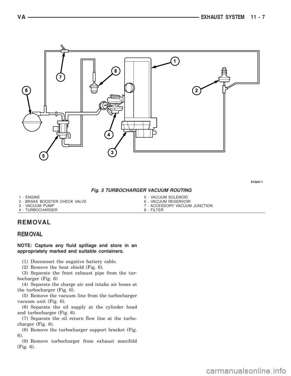
Fig. 5 TURBOCHARGER VACUUM ROUTING
1 - ENGINE 5 - VACUUM SOLENOID
2 - BRAKE BOOSTER CHECK VALVE 6 - VACUUM RESERVOIR
3 - VACUUM PUMP 7 - ACCESSORY VACUUM JUNCTION
4 - TURBOCHARGER 8 - FILTER
VAEXHAUST SYSTEM 11 - 7