water pump MERCEDES-BENZ SPRINTER 2006 Workshop Manual
[x] Cancel search | Manufacturer: MERCEDES-BENZ, Model Year: 2006, Model line: SPRINTER, Model: MERCEDES-BENZ SPRINTER 2006Pages: 2305, PDF Size: 48.12 MB
Page 1645 of 2305
(8) Install the exhaust hanger fasteners at the
muffler.
(9) Tighten the exhaust hanger bracket to engine
block.
(10) Install the turbocharger support bracket.
(11) Lower the vehicle.
(12) Install the air cleaner duct to the turbo-
charger (Fig. 71).
(13) Install the exhaust heat shield.
(14) Connect the negative battery cable.
TIMING CHAIN COVER
REMOVAL
WARNING: DO NOT OPEN COOLING SYSTEM
UNLESS TEMPERATURE IS BELOW 90ÉC (194ÉF).
OPEN CAP SLOWLY TO RELEASE PRESSURE.
STORE COOLANT IN APPROVED CONTAINER
ONLY. RISK OF INJURY TO SKIN AND EYES FROM
SCALDING COOLANT. WEAR PROTECTIVE
GLOVES, CLOTHING AND EYE WEAR.
(1) Disconnect negative battery cable.
NOTE: Rotate engine on crankshaft. DO NOT crank
the engine at the bolt of the camshaft sprocket.
NOTE: DO NOT crank engine back.
(2) Position piston of cylinder 1 to ignition TDC.
Markings on the camshaft bearing cap must be
aligned.
(3) Drain coolant (Refer to 7 - COOLING/ENGINE/
COOLANT - STANDARD PROCEDURE).
(4) Install retaining lock for crankshaft/starter
ring gear (Refer to 9 - ENGINE/ENGINE BLOCK/
FLEX PLATE - INSTALLATION).
(5) Drain engine oil.
(6) Remove the oil filter to allow the oil to flow off
into the oil pan.
(7) Remove the radiator assembly (Refer to 7 -
COOLING/ENGINE/RADIATOR - REMOVAL).
(8) Remove engine cover (Refer to 9 - ENGINE -
REMOVAL).
(9) Remove front cover at cylinder head (Refer to 9
- ENGINE/CYLINDER HEAD - REMOVAL).
(10) Remove accessory drive belt.
(11) Remove the high pressure fuel pump (Refer to
14 - FUEL SYSTEM/FUEL DELIVERY/FUEL PUMP
- REMOVAL).
(12) Remove water pump (Refer to 7 - COOLING/
ENGINE/WATER PUMP - REMOVAL).
(13) Remove accessory drive belt pulley and vibra-
tion damper (Refer to 9 - ENGINE/ENGINE BLOCK/
VIBRATION DAMPER - REMOVAL).
(14) Remove the power steering pump.NOTE: NO NOT open the air conditioning system.
(15) Unplug AC compressor electrical connector
and unbolt AC compressor. Relocate in lower engine
compartmentwith outopening the system.
(16) Remove the generator with wiring attached
and relocate somewhere in the engine compartment.
(17) Install engine support fixture.
(18) Remove the oil pan.
(19) Detach the coolant hose to oil-water heat
exchanger at crankcase (Fig. 73).
(20) Remove the cylinder head to timing cover
bolts (Fig. 73).
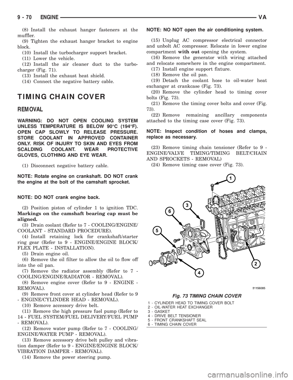
(21) Remove the timing cover bolts and cover (Fig.
73).
(22) Remove remaining ancillary components
attached to the timing case cover (Fig. 73).
NOTE: Inspect condition of hoses and clamps,
replace as necessary.
(23) Remove timing chain tensioner (Refer to 9 -
ENGINE/VALVE TIMING/TIMING BELT/CHAIN
AND SPROCKETS - REMOVAL)
(24) Remove timing case cover (Fig. 73).
Fig. 73 TIMING CHAIN COVER
1 - CYLINDER HEAD TO TIMING COVER BOLT
2 - OIL-WATER HEAT EXCHANGER
3 - GASKET
4 - DRIVE BELT TENSIONER
5 - FRONT CRANKSHAFT SEAL
6 - TIMING CHAIN COVER
9 - 70 ENGINEVA
Page 1646 of 2305
INSTALLATION
CAUTION: Care must be taken to closley inspect
the gasket area around the time case cover to cyl-
inder head gasket coolant port. If damage is found,
replace the cylinder head gasket. Failure to do so
may result in engine damage.
NOTE: Thoroughly clean all mating surfaces with
the appropriate solvents to assure that no grease or
oil is present during assembly.
(1) Inspect cylinder head gasket and oil pan gas-
ket. If damaged, replace.
(2) Replace the front crankshaft seal (Refer to 9 -
ENGINE/ENGINE BLOCK/CRANKSHAFT OIL
SEAL - FRONT - INSTALLATION).
(3) Install ancillary components to timing case
cover.
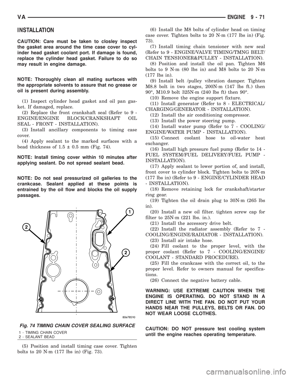
(4) Apply sealant to the marked surfaces with a
bead thickness of 1.5 0.5 mm (Fig. 74).
NOTE: Install timing cover within 10 minutes after
applying sealant. Do not spread sealant bead.
NOTE: Do not seal pressurized oil galleries to the
crankcase. Sealant applied at these points is
entrained by the oil flow and blocks the oil supply
passages.
(5) Position and install timing case cover. Tighten
bolts to 20 N´m (177 lbs in) (Fig. 73).(6) Install the M8 bolts of cylinder head on timing
case cover. Tighten bolts to 20 N´m (177 lbs in) (Fig.
73).
(7) Install timing chain tensioner with new seal
(Refer to 9 - ENGINE/VALVE TIMING/TMNG BELT/
CHAIN TENSIONER&PULLEY - INSTALLATION).
(8) Position and install the oil pan. Tighten M6
bolts to 9 N´m (80 lbs in) and M8 bolts to 20 N´m
(177 lbs in).
(9) Install belt /pulley vibration damper. Tighten
M8.8 bolt in two stages, 200N´m (147 lbs ft.) then
90É, M10.9 bolt 325N´m (240 lbs ft) then 90É.
(10) Remove the engine support fixture.
(11) Install generator (Refer to 8 - ELECTRICAL/
CHARGING/GENERATOR - INSTALLATION).
(12) Install the air conditioning compressor.
(13) Install the power steering pump.
(14) Install water pump (Refer to 7 - COOLING/
ENGINE/WATER PUMP - INSTALLATION).
(15) Connect coolant hose to oil-water heat
exchanger.
(16) Install high pressure fuel pump (Refer to 14 -
FUEL SYSTEM/FUEL DELIVERY/FUEL PUMP -
INSTALLATION).
(17) Apply sealant to lower portion of, and install,
front cover to cylinder block. Tighten bolts to 20N´m
(177 lbs in) (Refer to 9 - ENGINE/CYLINDER HEAD
- INSTALLATION).
(18) Remove retaining lock for crankshaft/starter
ring gear.
(19) Tighten the oil drain plug to 30N´m (265 lbs
in).
(20) Install a new oil filter. tighten screw cap for
filter to 25N´m (221 lbs. in.).
(21) Install the accessory drive belt.
(22) Install the radiator assembly (Refer to 7 -
COOLING/ENGINE/RADIATOR - INSTALLATION).
(23) Install air intake hose.
(24) Fill coolant to the proper level, with the
proper coolant (Refer to 7 - COOLING/ENGINE/
COOLANT - STANDARD PROCEDURE).
(25) Fill the crankcase with the correct oil, to the
proper level. Refer to owners manual for specifica-
tions.
(26) Connect the negative battery cable.
WARNING: USE EXTREME CAUTION WHEN THE
ENGINE IS OPERATING. DO NOT STAND IN A
DIRECT LINE WITH THE FAN. DO NOT PUT YOUR
HANDS NEAR THE PULLEYS, BELTS OR FAN. DO
NOT WEAR LOOSE CLOTHES.
CAUTION: DO NOT pressure test cooling system
until the engine reaches operating temperature.
Fig. 74 TIMING CHAIN COVER SEALING SURFACE
1 - TIMING CHAIN COVER
2 - SEALANT BEAD
VAENGINE 9 - 71
Page 1682 of 2305

FUEL SYSTEM
TABLE OF CONTENTS
page page
FUEL SYSTEM
WARNING
WARNING - HIGH FUEL SYSTEM
PRESSURE...........................1
WARNING............................1
DIAGNOSIS AND TESTING
DIAGNOSIS AND TESTING - HIGH
PRESSURE FUEL LINES.................1
DIAGNOSIS AND TESTING - AIR IN FUEL
SYSTEM.............................2
DIAGNOSIS AND TESTING - INJECTOR
LEAK QUANTITY.......................2STANDARD PROCEDURE
STANDARD PROCEDURES - CLEANING
FUEL SYSTEM COMPONENTS............3
STANDARD PROCEDURES - DRAINING
WATER FROM FUEL FILTER..............3
STANDARD PROCEDURE - LOW
PRESSURE FUEL PUMP TEST............4
FUEL DELIVERY..........................6
FUEL INJECTION........................31
FUEL SYSTEM
WARNING
WARNING - HIGH FUEL SYSTEM PRESSURE
WARNING: HIGH-PRESSURE FUEL LINES DELIVER
FUEL UNDER EXTREME PRESSURE FROM THE
INJECTION PUMP TO THE INJECTORS. THIS
MAYBE AS HIGH AS 1600BAR (23,200PSI). USE
EXTREME CAUTION WHEN INSPECTING FOR HIGH-
PRESSURE FUEL LEAKS. FUEL UNDER THIS
AMOUNT OF PRESSURE CAN PENETRATE SKIN
CAUSING PERSONAL INJURY OR DEATH. INSPECT
FOR HIGH-PRESSURE FUEL LEAKS WITH A SHEET
OF CARDBOARD PLACED IN THE SUSPECTED
AREA WHILE THE ENGINE IS NOT RUNNING.
START THE VEHICLE AND ALLOW THE ENGINE TO
RUN FOR A SHORT PERIOD. TURN THE ENGINE
OFF AND INSPECT THE PIECE OF CARDBOARD.
WEAR SAFETY GOGGLES AND ADEQUATE PRO-
TECTIVE CLOTHING WHEN SERVICING FUEL SYS-
TEM.
WARNING
WARNING: UNDER NO CIRCUMSTANCES SHOULD
GASOLINE BE MIXED WITH DIESEL FUEL (NOT
EVEN DURING WINTER). THE HIGH PRESSURE
PUMP IS LUBRICATED BY DIESEL FUEL. IMMEDI-
ATE FUEL SYSTEM DAMAGE MAY OCCUR CAUS-
ING REPLACEMENT AND FLUSHING OF THE
COMPLETE DIESEL FUEL SYSTEM. HIGH PRES-
SURE PUMP SEIZURE WILL CAUSE METAL PARTI-
CLES TO SPREAD THROUGH OUT THE FUELCIRCUIT. ALL CDI FUEL SYSTEM COMPONENTS
CONNECTED TO THE FUEL CIRCUIT WILL HAVE TO
BE EXCHANGED AND THE LINES FLUSHED.
DIAGNOSIS AND TESTING
DIAGNOSIS AND TESTING - HIGH PRESSURE
FUEL LINES
WARNING: HIGH-PRESSURE FUEL LINES DELIVER
FUEL UNDER EXTREME PRESSURE FROM THE
INJECTION PUMP TO THE INJECTORS. THIS
MAYBE AS HIGH AS 1600BAR (23,200PSI). USE
EXTREME CAUTION WHEN INSPECTING FOR HIGH-
PRESSURE FUEL LEAKS. FUEL UNDER THIS
AMOUNT OF PRESSURE CAN PENETRATE SKIN
CAUSING PERSONAL INJURY OR DEATH. INSPECT
FOR HIGH-PRESSURE FUEL LEAKS WITH A SHEET
OF CARDBOARD PLACED IN THE SUSPECTED
AREA WHILE THE ENGINE IS NOT RUNNING.
START THE VEHICLE AND ALLOW THE ENGINE TO
RUN FOR A SHORT PERIOD. TURN THE ENGINE
OFF AND INSPECT THE PIECE OF CARDBOARD.
WEAR SAFETY GOGGLES AND ADEQUATE PRO-
TECTIVE CLOTHING WHEN SERVICING FUEL SYS-
TEM.
High-pressure fuel line leaks can cause starting
problems and poor engine performance.
²Turn the engine off.
²Place a piece for cardboard in the suspected area
(Fig. 1).
²Start the engine and allow to run for a short
period.
²Turn the engine off.
²Inspect the cardboard.
VAFUEL SYSTEM 14 - 1
Page 1684 of 2305
(7) Connect a scan tool, select from Main Menu,
System Select, Engine, System Tests, Fuel Quantity
Test, Engine Cranking Test and follow the screen.
(8) After ten seconds, a maximum of 2.5 ml
(between2&3graduation lines) may be reached in
the inner vials. If the level has exceeded the 2.5 ml,
replace that affected cylinder's injector, clear the
memory using the scan tool, empty the test vials, and
retest.
RUNNING TEST
NOTE: If an injector is found to be out of specifica-
tion, repeat this test procedure after the injector
replacement. Hydraulic flow will take the path of
least resistance and multiple failures may be identi-
fied. Engine temperature must be above 80É C
(176ÉF) to perform the running test.
Perform this test with the engine at operating tem-
perature. This test will assist in determining a defec-
tive or internally leaking injector(s) is present by
measuring the amount of fuel return.
(1) Turn the ignition off.
(2) Remove the engine cover (Refer to 9 - ENGINE
- REMOVAL).
(3) Disconnect the fuel return hoses at the top of
the injectors.
(4) Pinch off the fuel return line at the banjo bolt
fitting of the fuel rail.
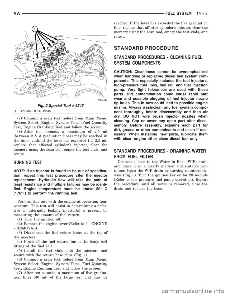
(5) Install the test vials onto the injectors and
secure with the return hose clips (Fig. 2).
(6) Connect a scan tool, select from Main Menu,
System Select, Engine, System Tests, Fuel Quantity
Test, Engine Running Test and follow the screen.
(7) After ten seconds, a maximum of five gradua-
tion lines (40 ml) of the large test vial may bereached. If the level has exceeded the five graduation
line, replace that affected cylinder's injector, clear the
memory using the scan tool, empty the test vials, and
retest.
STANDARD PROCEDURE
STANDARD PROCEDURES - CLEANING FUEL
SYSTEM COMPONENTS
CAUTION: Cleanliness cannot be overemphasized
when handling or replacing diesel fuel system com-
ponents. This especially includes the fuel injectors,
high-pressure fuel lines, fuel rail, and fuel injection
pump. Very tight tolerances are used with these
parts. Dirt contamination could cause rapid part
wear and possible plugging of fuel injector nozzle
tip holes. This in turn could lead to possible engine
misfire. Always wash/clean any fuel system compo-
nent thoroughly before disassembly and then air
dry. DO NOT wire brush injector nozzles when
cleaning. Cap or cover any open part after disas-
sembly. Before assembly, examine each part for
dirt, grease or other contaminants and clean if nec-
essary. When installing new parts, lubricate them
with clean engine oil or clean diesel fuel only.
STANDARD PROCEDURES - DRAINING WATER
FROM FUEL FILTER
Connect a hose to the Water in Fuel (WIF) drain
and place it in a clearly marked and suitable con-
tainer. Open the WIF drain by turning counterclock-
wise (Fig. 3). Turn the ignition key on for 20 seconds
(Refer to low pressure fuel pump operation). Repeat
the procedure until all water is removed, close the
drain and remove the hose.
Fig. 2 Special Tool # 9545
1 - SPECIAL TOOL #9545
VAFUEL SYSTEM 14 - 3
Page 1685 of 2305
STANDARD PROCEDURE - LOW PRESSURE
FUEL PUMP TEST
NOTE: Assure fuel tank quantity and proper fuel
gauge operation. Assure that the fuel pump fuse or
relay is not open. Capture any fuel spillage and
store in appropriately marked containers.
NOTE: When the ignition switch is turned to the ON
position the fuel pump will begin to run for 20±30
seconds and then it stops.
The low pressure pump draws fuel out of the fuel
tank module and pushes the fuel towards the fuel fil-
ter. If the pressure reading is below specification,
look for damaged or leaking fuel lines or a restricted
fuel filter. If no problem is found with the fuel sys-
tem replace the low pressure fuel pump.
(1) Disconnect the negative battery cable.
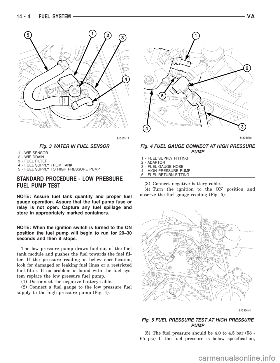
(2) Connect a fuel gauge to the low pressure fuel
supply to the high pressure pump (Fig. 4).(3) Connect negative battery cable.
(4) Turn the ignition to the ON position and
observe the fuel gauge reading (Fig. 5).
(5) The fuel pressure should be 4.0 to 4.5 bar (58 -
65 psi) If the fuel pressure is below specification,
Fig. 3 WATER IN FUEL SENSOR
1 - WIF SENSOR
2 - WIF DRAIN
3 - FUEL FILTER
4 - FUEL SUPPLY FROM TANK
5 - FUEL SUPPLY TO HIGH PRESSURE PUMP
Fig. 4 FUEL GAUGE CONNECT AT HIGH PRESSURE
PUMP
1 - FUEL SUPPLY FITTING
2 - ADAPTOR
3 - FUEL GAUGE HOSE
4 - HIGH PRESSURE PUMP
5 - FUEL RETURN FITTING
Fig. 5 FUEL PRESSURE TEST AT HIGH PRESSURE
PUMP
14 - 4 FUEL SYSTEMVA
Page 1687 of 2305

FUEL DELIVERY
TABLE OF CONTENTS
page page
FUEL DELIVERY
DESCRIPTION..........................6
OPERATION............................7
STANDARD PROCEDURE
STANDARD PROCEDURE - DRAINING
FUEL TANK - DIESEL...................8
FUEL CONTAMINATION.................8
SPECIFICATIONS
TORQUE.............................9
SPECIAL TOOLS
FUEL SYSTEM........................9
FUEL DRAIN TUBES
DIAGNOSIS AND TESTING - FUEL SUPPLY
RESTRICTIONS.......................10
FUEL FILTER
DESCRIPTION.........................10
REMOVAL.............................10
INSTALLATION.........................11
FUEL LINES
REMOVAL - HIGH PRESSURE LINES........11
INSTALLATION - HIGH PRESSURE LINES....12
FUEL RAIL PRESSURE SENSOR
DESCRIPTION.........................12
OPERATION...........................12
REMOVAL.............................12
INSTALLATION.........................13
FUEL PUMP
DESCRIPTION
DESCRIPTION - HIGH PRESSURE PUMP . . . 13
DESCRIPTION - LOW PRESSURE PUMP . . . 13OPERATION
OPERATION.........................13
OPERATION - LOW PRESSURE PUMP.....16
REMOVAL - HIGH PRESSURE PUMP........17
INSTALLATION - HIGH PRESSURE PUMP....17
FUEL PUMP MODULE
DESCRIPTION.........................18
REMOVAL.............................18
INSTALLATION.........................20
FUEL QUANTITY CONTROL VALVE
DESCRIPTION.........................21
OPERATION...........................21
REMOVAL.............................21
INSTALLATION.........................21
FUEL RAIL
DESCRIPTION.........................22
OPERATION...........................22
REMOVAL.............................22
INSTALLATION.........................22
FUEL TANK
DESCRIPTION.........................23
REMOVAL.............................25
INSTALLATION.........................26
FUEL LEVEL SENDING UNIT / SENSOR
DESCRIPTION.........................28
REMOVAL.............................29
INSTALLATION.........................29
WATER IN FUEL SENSOR
DESCRIPTION.........................30
OPERATION...........................30
FUEL DELIVERY
DESCRIPTION
Fuel is collected in the fuel tank. The fuel is drawn
in by the fuel pump module in the tank and distrib-
uted to the fuel filter and onto the high pressure fuel
pump. From there the fuel is distributed onto the
fuel rail and then to the various injectors. Any fuel
not needed flows back to the fuel tank through the
cooler lines and mixes with the cool fuel in the fuel
pump module bowl to be used again (Fig. 1).
14 - 6 FUEL DELIVERYVA
Page 1691 of 2305
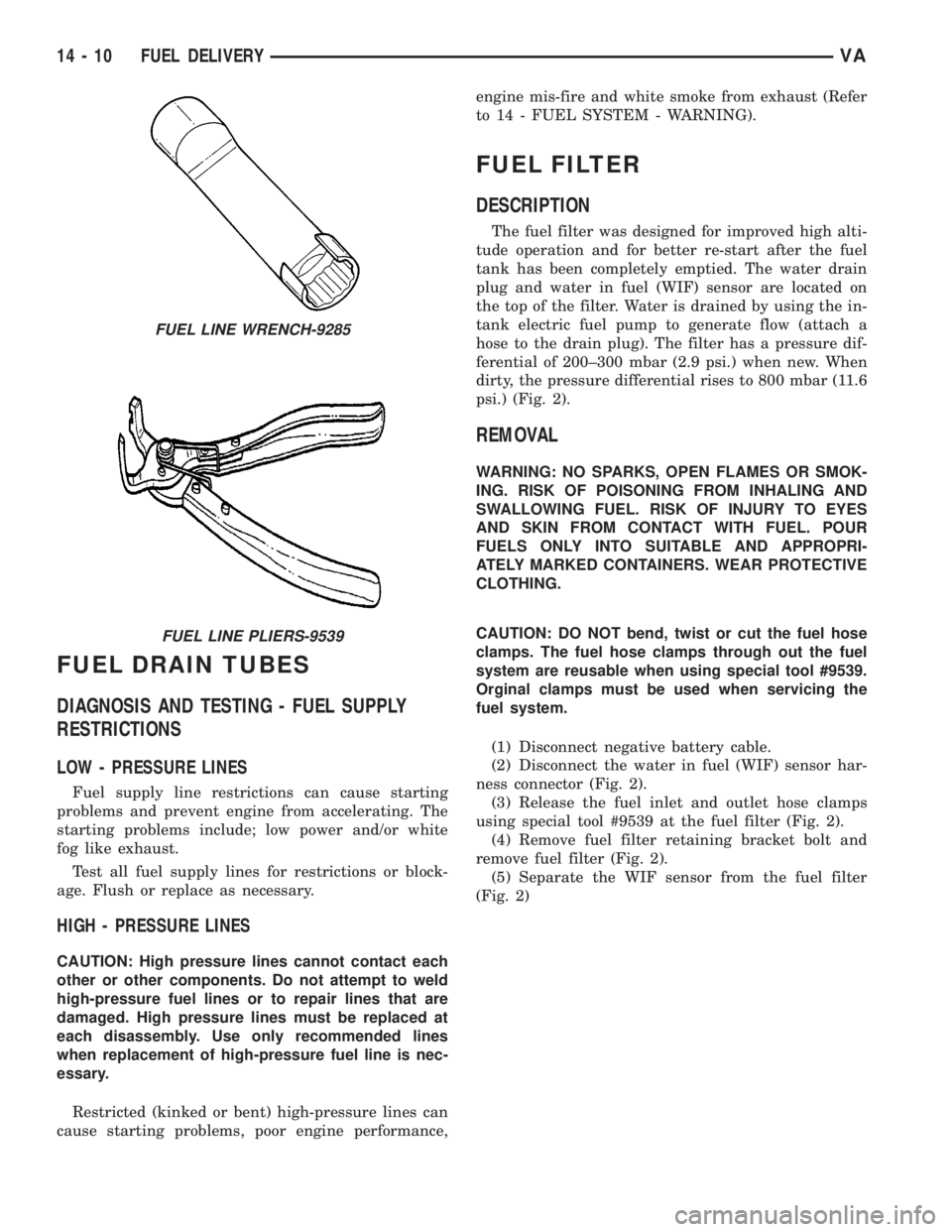
FUEL DRAIN TUBES
DIAGNOSIS AND TESTING - FUEL SUPPLY
RESTRICTIONS
LOW - PRESSURE LINES
Fuel supply line restrictions can cause starting
problems and prevent engine from accelerating. The
starting problems include; low power and/or white
fog like exhaust.
Test all fuel supply lines for restrictions or block-
age. Flush or replace as necessary.
HIGH - PRESSURE LINES
CAUTION: High pressure lines cannot contact each
other or other components. Do not attempt to weld
high-pressure fuel lines or to repair lines that are
damaged. High pressure lines must be replaced at
each disassembly. Use only recommended lines
when replacement of high-pressure fuel line is nec-
essary.
Restricted (kinked or bent) high-pressure lines can
cause starting problems, poor engine performance,engine mis-fire and white smoke from exhaust (Refer
to 14 - FUEL SYSTEM - WARNING).
FUEL FILTER
DESCRIPTION
The fuel filter was designed for improved high alti-
tude operation and for better re-start after the fuel
tank has been completely emptied. The water drain
plug and water in fuel (WIF) sensor are located on
the top of the filter. Water is drained by using the in-
tank electric fuel pump to generate flow (attach a
hose to the drain plug). The filter has a pressure dif-
ferential of 200±300 mbar (2.9 psi.) when new. When
dirty, the pressure differential rises to 800 mbar (11.6
psi.) (Fig. 2).
REMOVAL
WARNING: NO SPARKS, OPEN FLAMES OR SMOK-
ING. RISK OF POISONING FROM INHALING AND
SWALLOWING FUEL. RISK OF INJURY TO EYES
AND SKIN FROM CONTACT WITH FUEL. POUR
FUELS ONLY INTO SUITABLE AND APPROPRI-
ATELY MARKED CONTAINERS. WEAR PROTECTIVE
CLOTHING.
CAUTION: DO NOT bend, twist or cut the fuel hose
clamps. The fuel hose clamps through out the fuel
system are reusable when using special tool #9539.
Orginal clamps must be used when servicing the
fuel system.
(1) Disconnect negative battery cable.
(2) Disconnect the water in fuel (WIF) sensor har-
ness connector (Fig. 2).
(3) Release the fuel inlet and outlet hose clamps
using special tool #9539 at the fuel filter (Fig. 2).
(4) Remove fuel filter retaining bracket bolt and
remove fuel filter (Fig. 2).
(5) Separate the WIF sensor from the fuel filter
(Fig. 2)
FUEL LINE WRENCH-9285
FUEL LINE PLIERS-9539
14 - 10 FUEL DELIVERYVA
Page 1711 of 2305
WATER IN FUEL SENSOR
DESCRIPTION
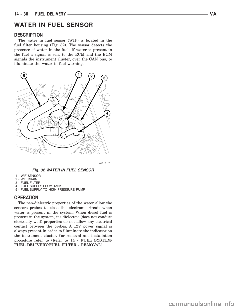
The water in fuel sensor (WIF) is located in the
fuel filter housing (Fig. 32). The sensor detects the
presence of water in the fuel. If water is present in
the fuel a signal is sent to the ECM and the ECM
signals the instrument cluster, over the CAN bus, to
illuminate the water in fuel warning.
OPERATION
The non-dielectric properties of the water allow the
sensors probes to close the electronic circuit when
water is present in the system. When diesel fuel is
present in the system, it's dielectric (does not conduct
electricity well) properties do not allow any electrical
contact between the probes. A 12V power signal is
always present in order to illuminate the indicator on
the instrument cluster. For removal and installation
procedure refer to (Refer to 14 - FUEL SYSTEM/
FUEL DELIVERY/FUEL FILTER - REMOVAL).
Fig. 32 WATER IN FUEL SENSOR
1 - WIF SENSOR
2 - WIF DRAIN
3 - FUEL FILTER
4 - FUEL SUPPLY FROM TANK
5 - FUEL SUPPLY TO HIGH PRESSURE PUMP
14 - 30 FUEL DELIVERYVA
Page 1727 of 2305
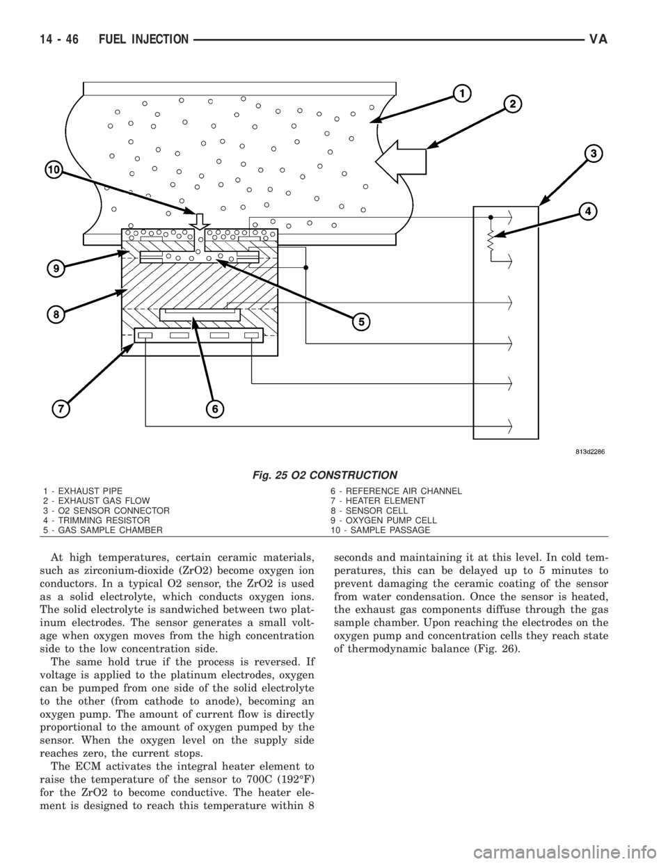
At high temperatures, certain ceramic materials,
such as zirconium-dioxide (ZrO2) become oxygen ion
conductors. In a typical O2 sensor, the ZrO2 is used
as a solid electrolyte, which conducts oxygen ions.
The solid electrolyte is sandwiched between two plat-
inum electrodes. The sensor generates a small volt-
age when oxygen moves from the high concentration
side to the low concentration side.
The same hold true if the process is reversed. If
voltage is applied to the platinum electrodes, oxygen
can be pumped from one side of the solid electrolyte
to the other (from cathode to anode), becoming an
oxygen pump. The amount of current flow is directly
proportional to the amount of oxygen pumped by the
sensor. When the oxygen level on the supply side
reaches zero, the current stops.
The ECM activates the integral heater element to
raise the temperature of the sensor to 700C (192ÉF)
for the ZrO2 to become conductive. The heater ele-
ment is designed to reach this temperature within 8seconds and maintaining it at this level. In cold tem-
peratures, this can be delayed up to 5 minutes to
prevent damaging the ceramic coating of the sensor
from water condensation. Once the sensor is heated,
the exhaust gas components diffuse through the gas
sample chamber. Upon reaching the electrodes on the
oxygen pump and concentration cells they reach state
of thermodynamic balance (Fig. 26).
Fig. 25 O2 CONSTRUCTION
1 - EXHAUST PIPE 6 - REFERENCE AIR CHANNEL
2 - EXHAUST GAS FLOW 7 - HEATER ELEMENT
3 - O2 SENSOR CONNECTOR 8 - SENSOR CELL
4 - TRIMMING RESISTOR 9 - OXYGEN PUMP CELL
5 - GAS SAMPLE CHAMBER 10 - SAMPLE PASSAGE
14 - 46 FUEL INJECTIONVA
Page 1730 of 2305
STEERING
TABLE OF CONTENTS
page page
STEERING
DESCRIPTION..........................1
OPERATION............................1
DIAGNOSIS AND TESTING - POWER
STEERING SYSTEM....................1COLUMN................................4
GEAR..................................7
LINKAGE................................9
PUMP..................................11
STEERING
DESCRIPTION
CAUTION: Use approved fluid only in the power
steering system (Refer to LUBRICATION & MAINTE-
NANCE/FLUID TYPES - DESCRIPTION). No other
power steering or automatic transmission fluid is to
be used in the system. Damage may result to the
power steering pump and system if any other fluid
is used, and do not overfill.
Power steering systems consist of:
²Steering column
²Rack and pinion steering gear
²Belt driven hydraulic steering pump
²Pump pressure and return hoses
²Oil Cooler
OPERATION
The steering column shaft is attached to the gear
pinion. The rotation of the pinion moves the gear
rack from side-to-side. This lateral action of the rack
pushes and pulls the tie rods to change the direction
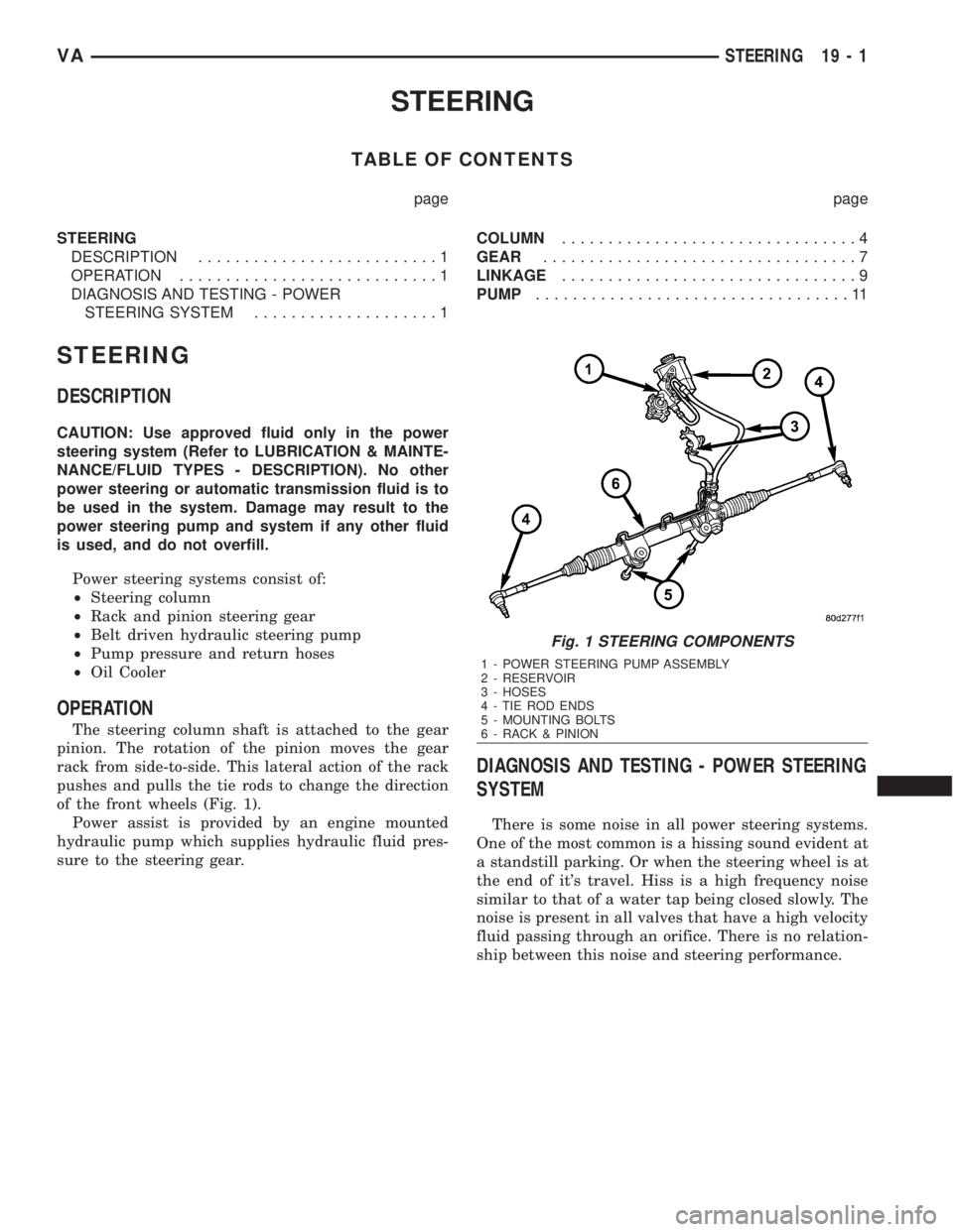
of the front wheels (Fig. 1).
Power assist is provided by an engine mounted
hydraulic pump which supplies hydraulic fluid pres-
sure to the steering gear.
DIAGNOSIS AND TESTING - POWER STEERING
SYSTEM
There is some noise in all power steering systems.
One of the most common is a hissing sound evident at
a standstill parking. Or when the steering wheel is at
the end of it's travel. Hiss is a high frequency noise
similar to that of a water tap being closed slowly. The
noise is present in all valves that have a high velocity
fluid passing through an orifice. There is no relation-
ship between this noise and steering performance.
Fig. 1 STEERING COMPONENTS
1 - POWER STEERING PUMP ASSEMBLY
2 - RESERVOIR
3 - HOSES
4 - TIE ROD ENDS
5 - MOUNTING BOLTS
6 - RACK & PINION
VASTEERING 19 - 1