water pump MERCEDES-BENZ SPRINTER 2006 Owner's Manual
[x] Cancel search | Manufacturer: MERCEDES-BENZ, Model Year: 2006, Model line: SPRINTER, Model: MERCEDES-BENZ SPRINTER 2006Pages: 2305, PDF Size: 48.12 MB
Page 847 of 2305
OPERATION
A vent valve in the center of the cap will remain
shut as long as the cooling system is pressurized. As
the coolant cools, it contracts and creates a vacuum
in cooling system. This causes the vacuum valve to
open and coolant in reserve/overflow tank to be
drawn through connecting hose into radiator. If the
vacuum valve is stuck shut, or overflow hose is
kinked, radiator hoses will collapse on cool-down.
DIAGNOSIS AND TESTING - RADIATOR PRES-
SURE CAP
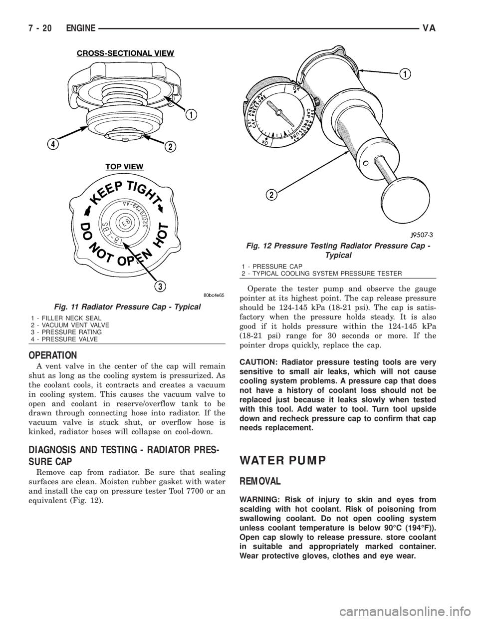
Remove cap from radiator. Be sure that sealing
surfaces are clean. Moisten rubber gasket with water
and install the cap on pressure tester Tool 7700 or an
equivalent (Fig. 12).Operate the tester pump and observe the gauge
pointer at its highest point. The cap release pressure
should be 124-145 kPa (18-21 psi). The cap is satis-
factory when the pressure holds steady. It is also
good if it holds pressure within the 124-145 kPa
(18-21 psi) range for 30 seconds or more. If the
pointer drops quickly, replace the cap.
CAUTION: Radiator pressure testing tools are very
sensitive to small air leaks, which will not cause
cooling system problems. A pressure cap that does
not have a history of coolant loss should not be
replaced just because it leaks slowly when tested
with this tool. Add water to tool. Turn tool upside
down and recheck pressure cap to confirm that cap
needs replacement.
WATER PUMP
REMOVAL
WARNING: Risk of injury to skin and eyes from
scalding with hot coolant. Risk of poisoning from
swallowing coolant. Do not open cooling system
unless coolant temperature is below 90ÉC (194ÉF)).
Open cap slowly to release pressure. store coolant
in suitable and appropriately marked container.
Wear protective gloves, clothes and eye wear.
Fig. 11 Radiator Pressure Cap - Typical
1 - FILLER NECK SEAL
2 - VACUUM VENT VALVE
3 - PRESSURE RATING
4 - PRESSURE VALVE
Fig. 12 Pressure Testing Radiator Pressure Cap -
Typical
1 - PRESSURE CAP
2 - TYPICAL COOLING SYSTEM PRESSURE TESTER
7 - 20 ENGINEVA
Page 848 of 2305
NOTE: Inspect condition of all clamps and hoses,
replace as necessary.
(1) Disconnect the negative battery cable.
(2) Drain cooling system (Refer to 7 - COOLING/
ENGINE/COOLANT - STANDARD PROCEDURE).
(3) Remove viscous fan clutch.
(4) Detach fuel lines from the brackets at the
water pump.
(5) Detach the coolant hoses at the water pump
(Fig. 13).
VAENGINE 7 - 21
Page 849 of 2305
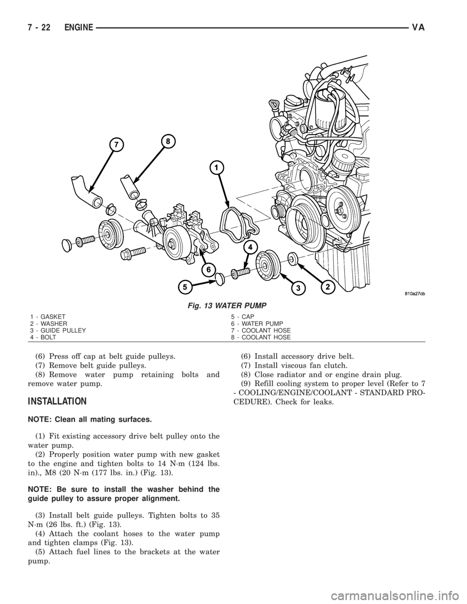
(6) Press off cap at belt guide pulleys.
(7) Remove belt guide pulleys.
(8) Remove water pump retaining bolts and
remove water pump.
INSTALLATION
NOTE: Clean all mating surfaces.
(1) Fit existing accessory drive belt pulley onto the
water pump.
(2) Properly position water pump with new gasket
to the engine and tighten bolts to 14 N´m (124 lbs.
in)., M8 (20 N´m (177 lbs. in.) (Fig. 13).
NOTE: Be sure to install the washer behind the
guide pulley to assure proper alignment.
(3) Install belt guide pulleys. Tighten bolts to 35
N´m (26 lbs. ft.) (Fig. 13).
(4) Attach the coolant hoses to the water pump
and tighten clamps (Fig. 13).
(5) Attach fuel lines to the brackets at the water
pump.(6) Install accessory drive belt.
(7) Install viscous fan clutch.
(8) Close radiator and or engine drain plug.
(9) Refill cooling system to proper level (Refer to 7
- COOLING/ENGINE/COOLANT - STANDARD PRO-
CEDURE). Check for leaks.
Fig. 13 WATER PUMP
1 - GASKET 5 - CAP
2 - WASHER 6 - WATER PUMP
3 - GUIDE PULLEY 7 - COOLANT HOSE
4 - BOLT 8 - COOLANT HOSE
7 - 22 ENGINEVA
Page 883 of 2305
SPECIAL TOOLS
GENERATOR
DESCRIPTION
The generator is belt-driven by the engine using a
serpentine-type drive belt. It is serviced only as a
complete assembly. If the generator fails for any rea-
son, the entire assembly must be replaced.
On certain engines, the decoupler pulley may be
replaced separately.
OPERATION
As the energized rotor begins to rotate within the
generator, the spinning magnetic field induces a cur-
rent into the windings of the stator coil. Once the
generator begins producing sufficient current, it also
provides the current needed to energize the rotor.
The stator winding connections deliver the induced
AC current to 3 positive and 3 negative diodes for
rectification. From the diodes, rectified DC current isdelivered to the vehicle electrical system through the
generator battery terminal.
Although the generators appear the same exter-
nally, different generators with different output rat-
ings are used on this vehicle. Be certain that the
replacement generator has the same output rating
and part number as the original unit. Refer to Spec-
ifications and see Generator Ratings for amperage
ratings and part numbers.
Noise emitting from the generator may be caused
by: worn, loose or defective bearings; a loose or defec-
tive drive pulley (decoupler pulley); incorrect, worn,
damaged or misadjusted fan drive belt; loose mount-
ing bolts; a misaligned drive pulley or a defective sta-
tor or diode.
An instrument panel mounted, battery charge indi-
cator lamp is used. When the key is in the on posi-
tion, the lamp will be illuminated. This is done as a
bulb check. If this lamp remains illuminated while
the engine is running, a Diagnostic Trouble Code
(DTC) has been detected for the charging system.
REMOVAL
CAUTION: DISCONNECT NEGATIVE CABLE FROM
BATTERY BEFORE REMOVING BATTERY OUTPUT
WIRE FROM GENERATOR. FAILURE TO DO SO
CAN RESULT IN INJURY.
CAUTION: Never force a belt over a pulley rim
using a screwdriver. The synthetic fiber of the belt
can be damaged.
CAUTION: When installing a serpentine accessory
drive belt, the belt MUST be routed correctly. The
water pump will be rotating in the wrong direction if
the belt is installed incorrectly, causing the engine
to overheat. Refer to belt routing label in engine
compartment, or refer to Belt Schematics in Cooling
System.
(1) Disconnect and isolate negative battery cable.
(2) Remove generator drive belt. Refer to Cooling
System for procedure.
(3) Raise and support vehicle.
(4) Remove protective plastic cover from B+ stud
at top of generator.
(5) Remove nut securing battery output cable to
B+ terminal at top of generator.
(6) Unplug field terminal connector at rear of gen-
erator.
(7) Remove 4 generator mounting bolts (Torx-style
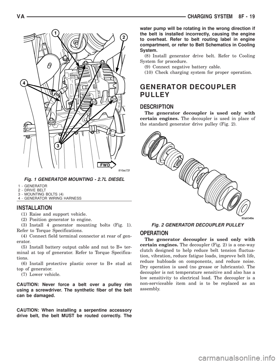
#12 bit) (Fig. 1).
(8) Remove generator from lower side of vehicle.
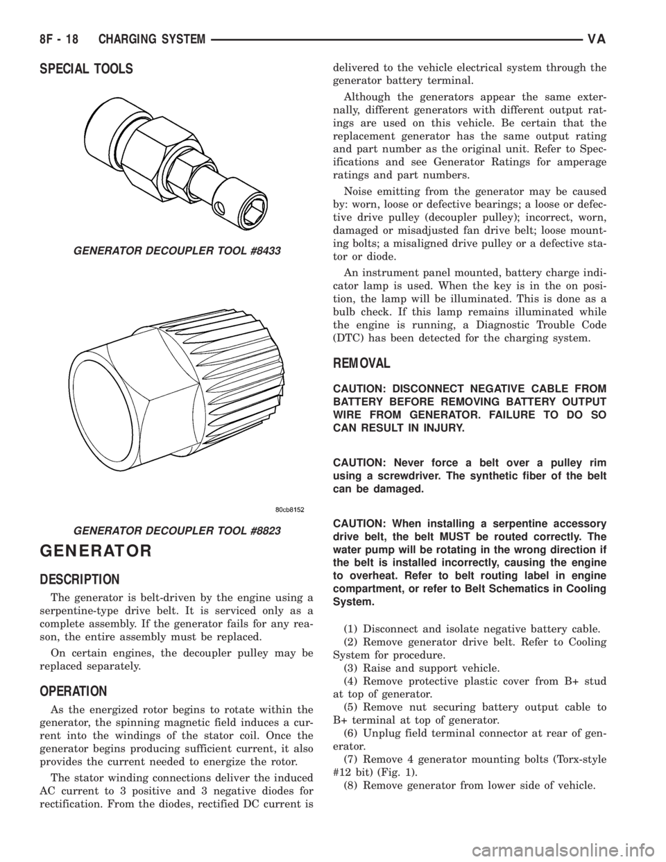
GENERATOR DECOUPLER TOOL #8433
GENERATOR DECOUPLER TOOL #8823
8F - 18 CHARGING SYSTEMVA
Page 884 of 2305
INSTALLATION
(1) Raise and support vehicle.
(2) Position generator to engine.
(3) Install 4 generator mounting bolts (Fig. 1).
Refer to Torque Specifications.
(4) Connect field terminal connector at rear of gen-
erator.
(5) Install battery output cable and nut to B+ ter-
minal at top of generator. Refer to Torque Specifica-
tions.
(6) Install protective plastic cover to B+ stud at
top of generator.
(7) Lower vehicle.
CAUTION: Never force a belt over a pulley rim
using a screwdriver. The synthetic fiber of the belt
can be damaged.
CAUTION: When installing a serpentine accessory
drive belt, the belt MUST be routed correctly. Thewater pump will be rotating in the wrong direction if
the belt is installed incorrectly, causing the engine
to overheat. Refer to belt routing label in engine
compartment, or refer to Belt Schematics in Cooling
System.
(8) Install generator drive belt. Refer to Cooling
System for procedure.
(9) Connect negative battery cable.
(10) Check charging system for proper operation.
GENERATOR DECOUPLER
PULLEY
DESCRIPTION
The generator decoupler is used only with
certain engines.The decoupler is used in place of
the standard generator drive pulley (Fig. 2).
OPERATION
The generator decoupler is used only with
certain engines.The decoupler (Fig. 2) is a one-way
clutch designed to help reduce belt tension fluctua-
tion, vibration, reduce fatigue loads, improve belt life,
reduce hubloads on components, and reduce noise.
Dry operation is used (no grease or lubricants). The
decoupler is not temperature sensitive and also has a
low sensitivity to electrical load. The decoupler is a
non-serviceable item and is to be replaced as an
assembly.
Fig. 1 GENERATOR MOUNTING - 2.7L DIESEL
1 - GENERATOR
2 - DRIVE BELT
3 - MOUNTING BOLTS (4)
4 - GENERATOR WIRING HARNESS
Fig. 2 GENERATOR DECOUPLER PULLEY
VACHARGING SYSTEM 8F - 19
Page 948 of 2305

The ECM continually monitors the engine coolant
temperature sensor to determine when the glow
plugs need to be energized in their pre-heat operat-
ing mode. The ECM then sends the proper wait-to-
start lamp-on and lamp-off messages to the
instrument cluster. If the instrument cluster turns on
the indicator after the engine is started, it may indi-
cate that a malfunction has occurred and that the
engine glow control system requires service. The
ECM will store a Diagnostic Trouble Code (DTC) for
any malfunction it detects. For proper diagnosis of
the engine coolant temperature sensor, the engine
glow control system and circuits, the ECM, the CAN
data bus, or the electronic message inputs to the
instrument cluster that control the wait-to-start indi-
cator, a diagnostic scan tool is required. Refer to the
appropriate diagnostic information.
WASHER FLUID INDICATOR
DESCRIPTION
A washer fluid indicator is standard equipment on
all instrument clusters. However, this indicator is
only functional on vehicles equipped with an optional
washer fluid level switch integral to the washer
pump/motor unit on the washer reservoir. The
washer fluid indicator is located near the lower edge
of the instrument cluster, to the right of the multi-
function indicator display. The washer fluid indicator
consists of the International Control and Display
Symbol icon for ªWindshield Washer Fluidº imprinted
within a rectangular cutout in the opaque layer of
the instrument cluster overlay. The dark outer layer
of the overlay prevents the indicator from being
clearly visible when it is not illuminated. An amber
Light Emitting Diode (LED) behind the cutout in the
opaque layer of the overlay causes the icon to appear
silhouetted against an amber field through the trans-
lucent outer layer of the overlay when the indicator
is illuminated from behind by the LED, which is sol-
dered onto the instrument cluster electronic circuit
board. The washer fluid indicator is serviced as a
unit with the instrument cluster.
OPERATION
The washer fluid indicator gives an indication to
the vehicle operator that the fluid level in the washer
reservoir is low. This indicator is controlled by the
instrument cluster circuit board based upon cluster
programming and a hard wired input from the
optional washer fluid level switch that is integral to
the washer pump/motor unit. The washer fluid indi-
cator is completely controlled by the instrument clus-
ter logic circuit, and that logic will only allow this
indicator to operate when the instrument cluster
detects that the ignition switch is in the On position.
Therefore, the indicator will always be off when theignition switch is in any position except On. The indi-
cator only illuminates when it is switched to ground
by the instrument cluster circuitry. The instrument
cluster will turn on the washer fluid indicator for the
following reasons:
²Bulb Test- Each time the ignition switch is
turned to the On position the brake wear indicator is
illuminated by the instrument cluster for about two
seconds as a bulb test.
²Washer Fluid Level Switch Input- Each time
the cluster detects ground on the washer fluid switch
sense circuit (washer fluid level switch closed =
washer fluid level low) while the ignition switch is in
the On position, the washer fluid indicator is illumi-
nated. The indicator remains illuminated until the
washer fluid level switch input to the cluster is an
open circuit (washer fluid level switch open = washer
fluid level acceptable), or until the ignition switch is
turned to the Off position, whichever occurs first.
The instrument cluster continually monitors the
washer fluid level switch to determine the level of
the washer fluid. The instrument cluster logic applies
a delay strategy to this input to reduce the negative
effect that fluid sloshing within the reservoir can
have on reliable indicator operation. The washer
fluid level switch and circuit can be diagnosed using
conventional diagnostic tools and methods. For
proper diagnosis of the instrument cluster circuitry
that controls the washer fluid indicator, a diagnostic
scan tool is required. Refer to the appropriate diag-
nostic information.
WATER - IN - FUEL INDICATOR
DESCRIPTION
A water-in-fuel indicator is standard equipment in
all instrument clusters. The water-in-fuel indicator is
located near the lower edge of the instrument cluster,
to the left of the multi-function indicator display. The
water-in-fuel indicator consists of the International
Control and Display Symbol icon for ªWater In Fuelº
imprinted within a rectangular cutout in the opaque
layer of the instrument cluster overlay. The dark
outer layer of the overlay prevents the indicator from
being clearly visible when it is not illuminated. An
amber Light Emitting Diode (LED) behind the cutout
in the opaque layer of the overlay causes the icon to
appear silhouetted against an amber field through
the translucent outer layer of the overlay when the
indicator is illuminated from behind by the LED,
which is soldered onto the instrument cluster elec-
tronic circuit board. The water-in-fuel indicator is
serviced as a unit with the instrument cluster.
OPERATION
The water-in-fuel indicator gives an indication to
the vehicle operator when there is excessive water
VAINSTRUMENT CLUSTER 8J - 29
Page 1052 of 2305

CONDITION POSSIBLE CAUSES CORRECTION
WIPERS DO NOT PARK
AFTER OPERATING1. Faulty park switch output circuit. 1. Test and repair the open or shorted cir-
cuit between the wiper park switch and
the rain sensor control module as re-
quired.
2. Faulty wiper relay output circuit. 2. Test and repair the open or shorted cir-
cuit between the rain sensor control mod-
ule and the wiper relay as required.
3. Faulty wiper relay. 3. Test and replace the wiper relay as re-
quired.
4. Faulty park switch. 4. Test and replace the wiper motor as
required.
5. Faulty intermittent wipe logic cir-
cuit.5. Replace the steering column fuse block
as required.
WASHERS INOPERATIVE 1. Faulty washer pump ground cir-
cuit.1. Test and repair the open ground circuit
as required.
2. Faulty washer pump request cir-
cuit.2. Test and repair the open washer pump
request circuit between the multi-function
switch and the rain sensor control module
as required.
3. Faulty muli-function switch. 3. Test and replace the multi-function
switch as required.
4. Faulty washer pump control cir-
cuit.4. Test and repair the open washer pump
control circuit between the rain sensor
control module and the washer pump as
required.
5. Faulty washer pump motor. 5. Test and replace the washer pump as
required.
CLEANING - WIPER & WASHER SYSTEM
WIPER SYSTEM
The squeegees of wiper blades exposed to the ele-
ments for a long time tend to lose their wiping effec-
tiveness. Periodic cleaning of the squeegees is
suggested to remove any deposits of salt or road film.
The wiper blades, arms, and windshield glass should
only be cleaned using a sponge or soft cloth and
windshield washer fluid, a mild detergent, or a non-
abrasive cleaner. If the wiper blades continue to
leave streaks, smears, hazing, or beading on the
glass after thorough cleaning of the squeegees and
the glass, the entire wiper blade assembly must be
replaced.
CAUTION: Protect the rubber squeegees of the
wiper blades from any petroleum-based cleaners,
solvents, or contaminants. These products can rap-
idly deteriorate the rubber squeegees.
WASHER SYSTEM
If the washer system is contaminated with foreign
material, drain the washer reservoir by removing the
washer pump/motor from the reservoir. Clean foreign
material from the inside of the washer pump/motor
inlet nipple and the washer reservoir using clean
washer fluid, a mild detergent, or a non-abrasive
cleaner. Flush foreign material from the washer sys-
tem plumbing by first disconnecting the washer
hoses from the washer nozzles, then running the
washer pump/motor to run clean washer fluid or
water through the system. Plugged or restricted
washer nozzles should be carefully back-flushed
using compressed air. If the washer nozzle obstruc-
tion cannot be cleared, replace the washer nozzle.
CAUTION: Never introduce petroleum-based clean-
ers, solvents, or contaminants into the washer sys-
tem. These products can rapidly deteriorate the
rubber seals and hoses of the washer system, as
well as the rubber squeegees of the wiper blades.
VAWIPERS/WASHERS 8R - 9
Page 1054 of 2305
CHECK VALVE
DESCRIPTION
A single washer system check valve is standard
equipment on this model, and is installed in the
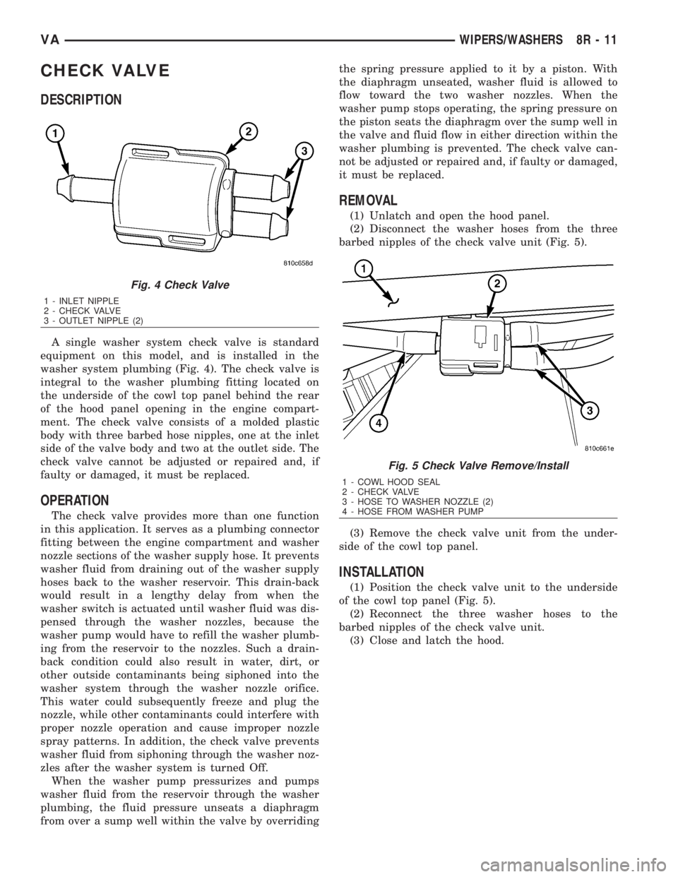
washer system plumbing (Fig. 4). The check valve is
integral to the washer plumbing fitting located on
the underside of the cowl top panel behind the rear
of the hood panel opening in the engine compart-
ment. The check valve consists of a molded plastic
body with three barbed hose nipples, one at the inlet
side of the valve body and two at the outlet side. The
check valve cannot be adjusted or repaired and, if
faulty or damaged, it must be replaced.
OPERATION
The check valve provides more than one function
in this application. It serves as a plumbing connector
fitting between the engine compartment and washer
nozzle sections of the washer supply hose. It prevents
washer fluid from draining out of the washer supply
hoses back to the washer reservoir. This drain-back
would result in a lengthy delay from when the
washer switch is actuated until washer fluid was dis-
pensed through the washer nozzles, because the
washer pump would have to refill the washer plumb-
ing from the reservoir to the nozzles. Such a drain-
back condition could also result in water, dirt, or
other outside contaminants being siphoned into the
washer system through the washer nozzle orifice.
This water could subsequently freeze and plug the
nozzle, while other contaminants could interfere with
proper nozzle operation and cause improper nozzle
spray patterns. In addition, the check valve prevents
washer fluid from siphoning through the washer noz-
zles after the washer system is turned Off.
When the washer pump pressurizes and pumps
washer fluid from the reservoir through the washer
plumbing, the fluid pressure unseats a diaphragm
from over a sump well within the valve by overridingthe spring pressure applied to it by a piston. With
the diaphragm unseated, washer fluid is allowed to
flow toward the two washer nozzles. When the
washer pump stops operating, the spring pressure on
the piston seats the diaphragm over the sump well in
the valve and fluid flow in either direction within the
washer plumbing is prevented. The check valve can-
not be adjusted or repaired and, if faulty or damaged,
it must be replaced.
REMOVAL
(1) Unlatch and open the hood panel.
(2) Disconnect the washer hoses from the three
barbed nipples of the check valve unit (Fig. 5).
(3) Remove the check valve unit from the under-
side of the cowl top panel.
INSTALLATION
(1) Position the check valve unit to the underside
of the cowl top panel (Fig. 5).
(2) Reconnect the three washer hoses to the
barbed nipples of the check valve unit.
(3) Close and latch the hood.
Fig. 4 Check Valve
1 - INLET NIPPLE
2 - CHECK VALVE
3 - OUTLET NIPPLE (2)
Fig. 5 Check Valve Remove/Install
1 - COWL HOOD SEAL
2 - CHECK VALVE
3 - HOSE TO WASHER NOZZLE (2)
4 - HOSE FROM WASHER PUMP
VAWIPERS/WASHERS 8R - 11
Page 1093 of 2305
Component Page
Ignition Lock Switch................... 8W-40
Ignition Switch....................... 8W-10
Instrument Cluster.................... 8W-40
Instrument Panel Socket................ 8W-41
Intake Air Pressure Sensor.............. 8W-30
Intake Air Temperature Sensor........... 8W-30
Interference Suppression Capacitor........ 8W-42
Interior Lamps....................... 8W-44
Interior Light Switches................. 8W-44
Interior Lighting Connector.............. 8W-44
Intrusion Sensors..................... 8W-39
Kickdown Switch...................... 8W-30
Lamp Relays......................... 8W-50
Lateral Acceleration Sensor.............. 8W-35
License Plate Lamps................... 8W-51
Lockeres............................ 8W-31
Low Fuel Pressure Sensor............... 8W-30
Low Pressure Switch................... 8W-42
Map/Reading Lamp Switch.............. 8W-44
Marker Lamp Connector................ 8W-51
Marker Lamps..................... 8W-50, 51
Mass Air Flow Sensor.................. 8W-30
Master Door Lock Switch............... 8W-61
Metering Pump....................... 8W-42
Microphone Connector.................. 8W-55
Multi-Function Switch......... 8W-50, 52, 53, 54
Optional Equipment Relay.............. 8W-11
Oxygen Sensor....................... 8W-30
Panic Alarm Switch.................... 8W-39
Parking Brake Switch.................. 8W-35
Power Distribution Center.............. 8W-10
Power Mirror Motors................... 8W-62
Power Mirror Switch................... 8W-62
Power Window Motors.................. 8W-60
Power Window Switches................ 8W-60
Radio............................... 8W-47
Radio Antenna........................ 8W-47
Radio/Cellular Antenna................. 8W-55
Rain Sensor.......................... 8W-53
Rain Sensor Control Module............. 8W-53
Reading Lamp Connector............... 8W-44
Rear Window Defogger Relay............ 8W-48
Recirculated Air Solenoid Valve........... 8W-42
Refrigerant Pressure Sensor............. 8W-42
Relay Block.......................... 8W-11
Rollover Switch....................... 8W-42
Rollover Switch Assembly............... 8W-42
Roof A/C Blower Fuses................. 8W-42
Roof A/C Blower Stage Relays............ 8W-42
Roof A/C Blowers...................... 8W-42
Roof A/C Compressor Fuse.............. 8W-42Component Page
Roof A/C Control Module................ 8W-42
Roof A/C Fan Fuse.................... 8W-42
Roof A/C Switch....................... 8W-42
Roof A/C Temperature Setting Control..... 8W-42
Roof Fan Motor....................... 8W-42
Roof Fan Switch...................... 8W-42
Roof Thermotronic Control Module........ 8W-42
SKREEM Antenna.................... 8W-39
SKREEM Transponder................. 8W-39
Seat Belt Switch...................... 8W-43
Seat Belt Tensioners................... 8W-43
Security System Module................ 8W-39
Sentry Key Remote Entry Module......... 8W-39
Shifter Assembly...................... 8W-31
Siren............................... 8W-41
Speakers............................ 8W-47
Speed Control Switch.................. 8W-33
Splices.............................. 8W-70
Starter Motor........................ 8W-21
Starter Motor Relay................... 8W-21
Steering Angle Sensor.................. 8W-35
TCS Switch.......................... 8W-35
Tail Lamp Assemblies.................. 8W-51
Temperature Sensor................... 8W-42
Thermotronic Diode.................... 8W-42
Time Delay Relay..................... 8W-44
Towing/Intrusion Sensor On/Off Switch..... 8W-39
Trailer Tow Connector.................. 8W-54
Trailer Tow Control Module.............. 8W-54
Transmission Control Module............ 8W-31
Transmission Relay.................... 8W-31
Turn Signal Relay..................... 8W-52
Turn Signal Switch.................... 8W-50
Turn Signal/Anti-Theft Alarm Relays...... 8W-39
Turn Signals......................... 8W-52
Warm Air Auxiliary Control Module....... 8W-42
Warm Air Auxiliary Heater Assembly...... 8W-42
Washer On/Off Switch.................. 8W-53
Washer Pump Motor-Front.............. 8W-53
Water Cycle Valve..................... 8W-42
Water In Fuel Sensor.................. 8W-30
Wheel Speed Sensors................... 8W-35
Window Defogger Module-Rear........... 8W-48
Window Defogger Switch-Rear........... 8W-48
Window Defoggers..................... 8W-48
Wiper Motor-Front.................... 8W-53
Wiper On/Off Relay.................... 8W-53
Wiper Switch......................... 8W-53
Wiper/Turn Signal/Engine Start Control
Module................... 8W-30, 31, 52, 53
8W - 02 - 2 8W-02 COMPONENT INDEXVA
Page 1168 of 2305
8W-15 GROUND DISTRIBUTION
Component PageA/C Auxiliary Fan..........................8W-15-4
A/C Auxiliary Fan Relay......................8W-15-12
A/C Compressor Clutch Relay...................8W-15-30
A/C Roof Auxiliary Fan......................8W-15-30
A/C Roof Auxiliary Fan Relay...................8W-15-30
Additional Heat Exchanger....................8W-15-12
Additional Heat Exchanger Relay.................8W-15-12
Additional Heat Exchanger Switch................8W-15-24
Airbag Control Module.......................8W-15-11
Ash Receiver Lamp........................8W-15-22
Automatic Temperature Control Module.............8W-15-24
Auxiliary Heater Control.....................8W-15-24
Battery................................8W-15-8
Battery Relay-Auxiliary......................8W-15-11
Battery-Auxiliary..........................8W-15-11
Blower Motor-Front.........................8W-15-9
Brake Fluid Level Switch......................8W-15-8
Brake Wear Sensor-Left Front...................8W-15-8
Brake Wear Sensor-Left Rear...................8W-15-28
Brake Wear Sensor-Right Front..................8W-15-8
Brake Wear Sensor-Right Rear..................8W-15-28
CTEL Connector..........................8W-15-21
Cabin Heater Module........................8W-15-3
Center High Mounted Stop Lamp.................8W-15-6
Central Timer Module.......................8W-15-15
Cigar Lighter............................8W-15-22
Cigar Lighter Lamp........................8W-15-22
Circulation Pump..........................8W-15-9
Circulation Pump Relay-Cabin Heater Module..........8W-15-12
Clockspring.............................8W-15-10
Controller Antilock Brake....................8W-15-2, 28
Crankcase Heater..........................8W-15-4
Cylinder Lock Switch-Driver...................8W-15-10
D+ Relay No. 1...........................8W-15-12
D+ Relay No. 2...........................8W-15-14
Data Link Connector........................8W-15-10
Daytime Running Lamp Relay-Left Side.............8W-15-13
Daytime Running Lamp Relay-Right Side............8W-15-13
Daytime Running Lamps Relay..................8W-15-13
Differential Lock Solenoid Valve..................8W-15-2
Dome Lamp.............................8W-15-6
Dosing Pump............................8W-15-2
Engine Control Module.......................8W-15-7
Engine Coolant Level Switch....................8W-15-2
Fan Stage 1 Relay.........................8W-15-11
Fog Lamp Relay..........................8W-15-11
Fog Lamp Switch.........................8W-15-22
Fuel Pump.............................8W-15-19
Fuse Block No. 1..........................8W-15-7
Fused Ignition Switch Run-Start Relay..............8W-15-14
G100...............................8W-15-2, 3
G101.................................8W-15-4
G102.................................8W-15-4
G103.................................8W-15-4
G200...........................8W-15-6, 7, 8, 9, 10
G201................................8W-15-11
G202................8W-15-11, 12, 13, 14, 15, 16, 17, 18, 19
G203......................8W-15-20, 21, 22, 23, 24, 25
G300............................8W-15-26, 27, 28
G301................................8W-15-28
G302................................8W-15-28
G303................................8W-15-31
G304................................8W-15-31
G305..............................8W-15-29, 30
Glow Plug Control Module.....................8W-15-2
Hazard Warning Switch.......................8W-15-7
Headlamp Adjust Switch.....................8W-15-22
Headlamp Assembly-Left......................8W-15-3
Headlamp Assembly-Right.....................8W-15-4
Heated Seat Module-Driver....................8W-15-19
Heated Seat Module-Passenger..................8W-15-19
Heated Seat Switch-Driver....................8W-15-25
Heated Seat Switch-Passenger..................8W-15-25
Heater Timer-Auxiliary......................8W-15-24
High Idle Switch..........................8W-15-25
Hood Ajar Switch..........................8W-15-4
Horn Relay.............................8W-15-11
Horn Switch............................8W-15-10
Ignition Lock Switch........................8W-15-10
Instrument Cluster........................8W-15-10
Instrument Panel Socket.....................8W-15-20
Interior Lamp No. 1.........................8W-15-6
Interior Lamp No. 2.........................8W-15-6
Interior Lamp No. 3.........................8W-15-6Component PageInterior Lamp No. 4.........................8W-15-6
Interior Lamp No. 5.........................8W-15-6
Interior Lamp-Left.........................8W-15-6
Interior Lamp-Middle Front...................8W-15-5, 6
Interior Lamp-Middle Rear...................8W-15-5, 6
Interior Lamp-Rear No. 2......................8W-15-5
Interior Lamp-Right.......................8W-15-5, 6
Interior Light Switch.......................8W-15-21
Interior Lighting Connector.....................8W-15-6
Intrusion Sensor No. 1.......................8W-15-6
Intrusion Sensor No. 2.......................8W-15-6
Intrusion Sensor No. 3.......................8W-15-6
Kickdown Switch..........................8W-15-8
Lamp Relay-Left..........................8W-15-13
Lamp Relay-Right.........................8W-15-13
License Plate Lamp No. 1.....................8W-15-27
License Plate Lamp No. 2.....................8W-15-27
Locker Switch No. 1........................8W-15-20
Map/Reading Lamp Switch....................8W-15-21
Marker Lamp Connector......................8W-15-17
Marker Lamp No. 1-Left Front..................8W-15-16
Marker Lamp No. 1-Right Front.................8W-15-16
Marker Lamp No. 2-Left Front..................8W-15-16
Marker Lamp No. 2-Right Front.................8W-15-16
Marker Lamp-Left Center.....................8W-15-17
Marker Lamp-Left Rear......................8W-15-27
Marker Lamp-Right Center....................8W-15-17
Marker Lamp-Right Rear.....................8W-15-27
Master Door Lock Switch.....................8W-15-25
Metering Pump...........................8W-15-18
Multi-Function Switch.......................8W-15-7
Optional Equipment Relay....................8W-15-19
Panic Alarm Switch........................8W-15-20
Parking Brake Switch.......................8W-15-15
Power Mirror Motor-Driver....................8W-15-23
Power Mirror Motor-Passenger..................8W-15-23
Power Mirror Switch........................8W-15-23
Power Window Switch-Driver...................8W-15-23
Power Window Switch-Master...................8W-15-23
Radio................................8W-15-21
Rain Sensor............................8W-15-31
Rain Sensor Control Module..................8W-15-19, 31
Reading Lamp Connector......................8W-15-6
Rear Window Defogger Relay...................8W-15-14
Recirculated Air Solenoid Valve...................8W-15-9
Rollover Switch Assembly......................8W-15-3
Roof A/C Blower..........................8W-15-29
Roof A/C Blower Stage I And Ii Relay...............8W-15-29
Roof A/C Blower Stage I Relay..................8W-15-29
Roof A/C Blower Stage Ii Relay..................8W-15-29
Roof A/C Control Module.....................8W-15-28
Roof A/C Switch..........................8W-15-24
Roof Fan Switch..........................8W-15-21
Roof Thermotronic Control Module................8W-15-30
Seat Belt Switch..........................8W-15-15
Security System Module......................8W-15-15
Sentry Key Remote Entry Module.................8W-15-7
Shifter Assembly..........................8W-15-20
Siren.................................8W-15-9
Steering Angle Sensor........................8W-15-7
TCS Switch.............................8W-15-25
Tail Lamp Assembly-Left.....................8W-15-26
Tail Lamp Assembly-Right.....................8W-15-26
Thermotronic Diode........................8W-15-30
Time Delay Relay.........................8W-15-17
Towing/Intrusion Sensor On/Off Switch..............8W-15-22
Trailer Tow Connector.......................8W-15-28
Trailer Tow Control Module....................8W-15-19
Transmission Control Module...................8W-15-19
Transmission Relay........................8W-15-19
Turn Signal No. 1-Left Front....................8W-15-3
Turn Signal No. 1-Right Front...................8W-15-4
Turn Signal No. 2-Left Front....................8W-15-3
Turn Signal No. 2-Right Front...................8W-15-4
Warm Air Auxiliary Heater Assembly...............8W-15-18
Washer Pump Motor-Front.....................8W-15-4
Water Cycle Valve..........................8W-15-9
Window Defogger Module-Rear..................8W-15-15
Window Defogger Switch-Rear..................8W-15-20
Window Defogger-Left Rear....................8W-15-26
Window Defogger-Right Rear...................8W-15-26
Wiper Motor-Front.........................8W-15-9
Wiper/Turn Signal/Engine Start Control Module.........8W-15-7
VA8W-15 GROUND DISTRIBUTION 8W - 15 - 1