wiring diagram MERCEDES-BENZ SPRINTER 2006 Repair Manual
[x] Cancel search | Manufacturer: MERCEDES-BENZ, Model Year: 2006, Model line: SPRINTER, Model: MERCEDES-BENZ SPRINTER 2006Pages: 2305, PDF Size: 48.12 MB
Page 371 of 2305
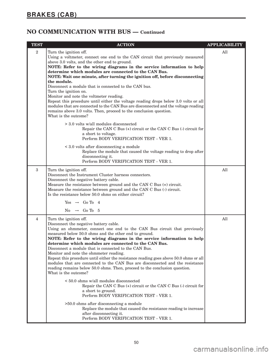
TEST ACTION APPLICABILITY
2 Turn the ignition off.
Using a voltmeter, connect one end to the CAN circuit that previously measured
above 3.0 volts, and the other end to ground.
NOTE: Refer to the wiring diagrams in the service information to help
determine which modules are connected to the CAN Bus.
NOTE: Wait one minute, after turning the ignition off, before disconnecting
the module.
Disconnect a module that is connected to the CAN bus.
Turn the ignition on.
Monitor and note the voltmeter reading.
Repeat this procedure until either the voltage reading drops below 3.0 volts or all
modules that are connected to the CAN Bus are disconnected and the voltage reading
remains above 3.0 volts. Then, proceed to the conclusion question.
What is the outcome?All
> 3.0 volts w/all modules disconnected
Repair the CAN C Bus (+) circuit or the CAN C Bus (-) circuit for
a short to voltage.
Perform BODY VERIFICATION TEST - VER 1.
< 3.0 volts after disconnecting a module
Replace the module that caused the voltage reading to drop after
disconnecting it.
Perform BODY VERIFICATION TEST - VER 1.
3 Turn the ignition off.
Disconnect the Instrument Cluster harness connectors.
Disconnect the negative battery cable.
Measure the resistance between ground and the CAN C Bus (+) circuit.
Measure the resistance between ground and the CAN C Bus (-) circuit.
Is the resistance below 50.0 ohms on either circuit?All
Ye s!Go To 4
No!Go To 5
4 Turn the ignition off.
Disconnect the negative battery cable.
Using an ohmmeter, connect one end to the CAN Bus circuit that previously
measured below 50.0 ohms and the other end to ground.
NOTE: Refer to the wiring diagrams in the service information to help
determine which modules are connected to the CAN Bus.
Disconnect a module that is connected to the CAN Bus.
Monitor and note the ohmmeter reading.
Repeat this procedure until either the resistance reading goes above 50.0 ohms or all
modules that are connected to the CAN Bus are disconnected and the resistance
reading remains below 50.0 ohms. Then, proceed to the conclusion question.
What is the outcome?All
< 50.0 ohms w/all modules disconnected
Repair the CAN C Bus (+) circuit or the CAN C Bus (-) circuit for
a short to ground.
Perform BODY VERIFICATION TEST - VER 1.
>50.0 ohms after disconnecting a module
Replace the module that caused the resistance reading to increase
after disconnecting it.
Perform BODY VERIFICATION TEST - VER 1.
50
BRAKES (CAB)
NO COMMUNICATION WITH BUS ÐContinued
Page 372 of 2305
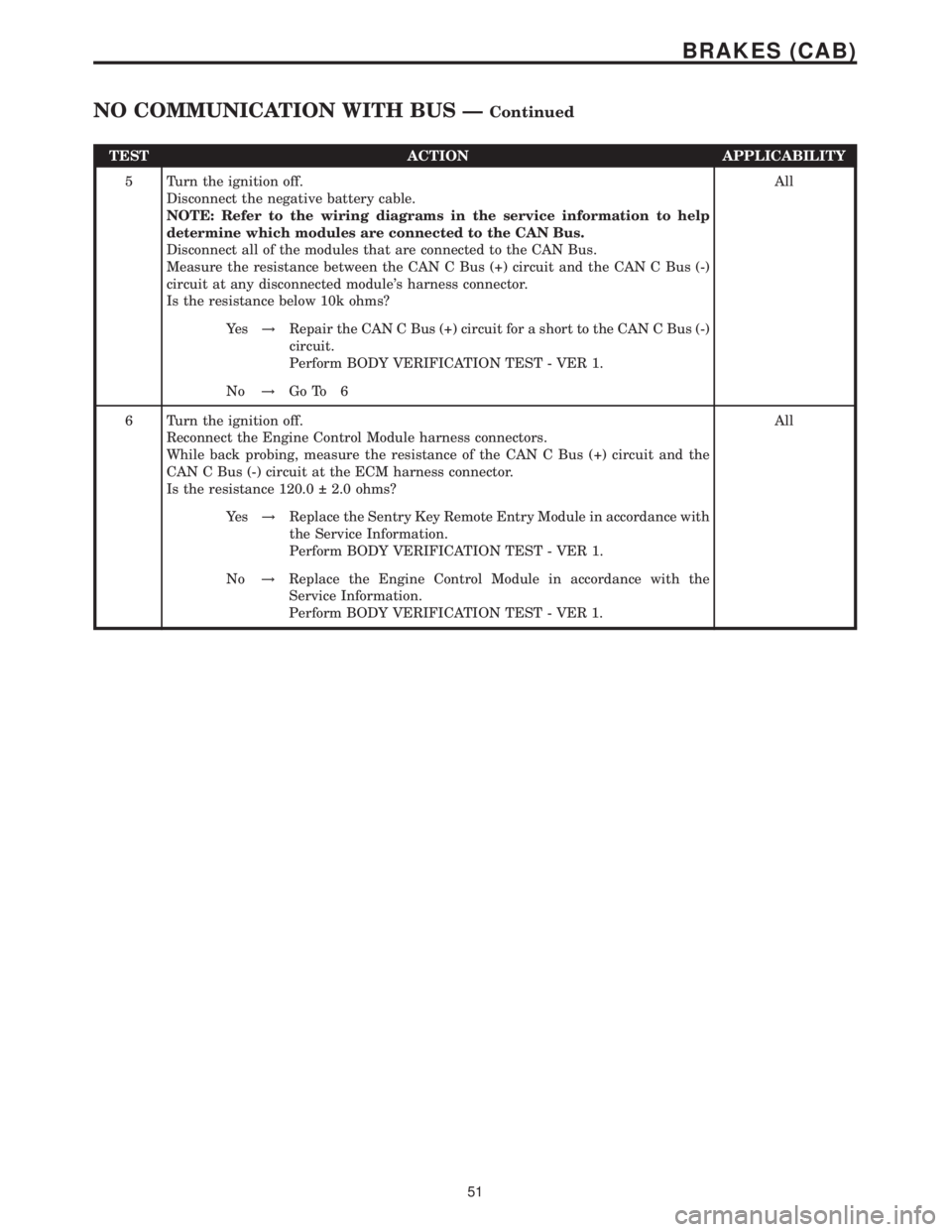
TEST ACTION APPLICABILITY
5 Turn the ignition off.
Disconnect the negative battery cable.
NOTE: Refer to the wiring diagrams in the service information to help
determine which modules are connected to the CAN Bus.
Disconnect all of the modules that are connected to the CAN Bus.
Measure the resistance between the CAN C Bus (+) circuit and the CAN C Bus (-)
circuit at any disconnected module's harness connector.
Is the resistance below 10k ohms?All
Ye s!Repair the CAN C Bus (+) circuit for a short to the CAN C Bus (-)
circuit.
Perform BODY VERIFICATION TEST - VER 1.
No!Go To 6
6 Turn the ignition off.
Reconnect the Engine Control Module harness connectors.
While back probing, measure the resistance of the CAN C Bus (+) circuit and the
CAN C Bus (-) circuit at the ECM harness connector.
Is the resistance 120.0 2.0 ohms?All
Ye s!Replace the Sentry Key Remote Entry Module in accordance with
the Service Information.
Perform BODY VERIFICATION TEST - VER 1.
No!Replace the Engine Control Module in accordance with the
Service Information.
Perform BODY VERIFICATION TEST - VER 1.
51
BRAKES (CAB)
NO COMMUNICATION WITH BUS ÐContinued
Page 427 of 2305
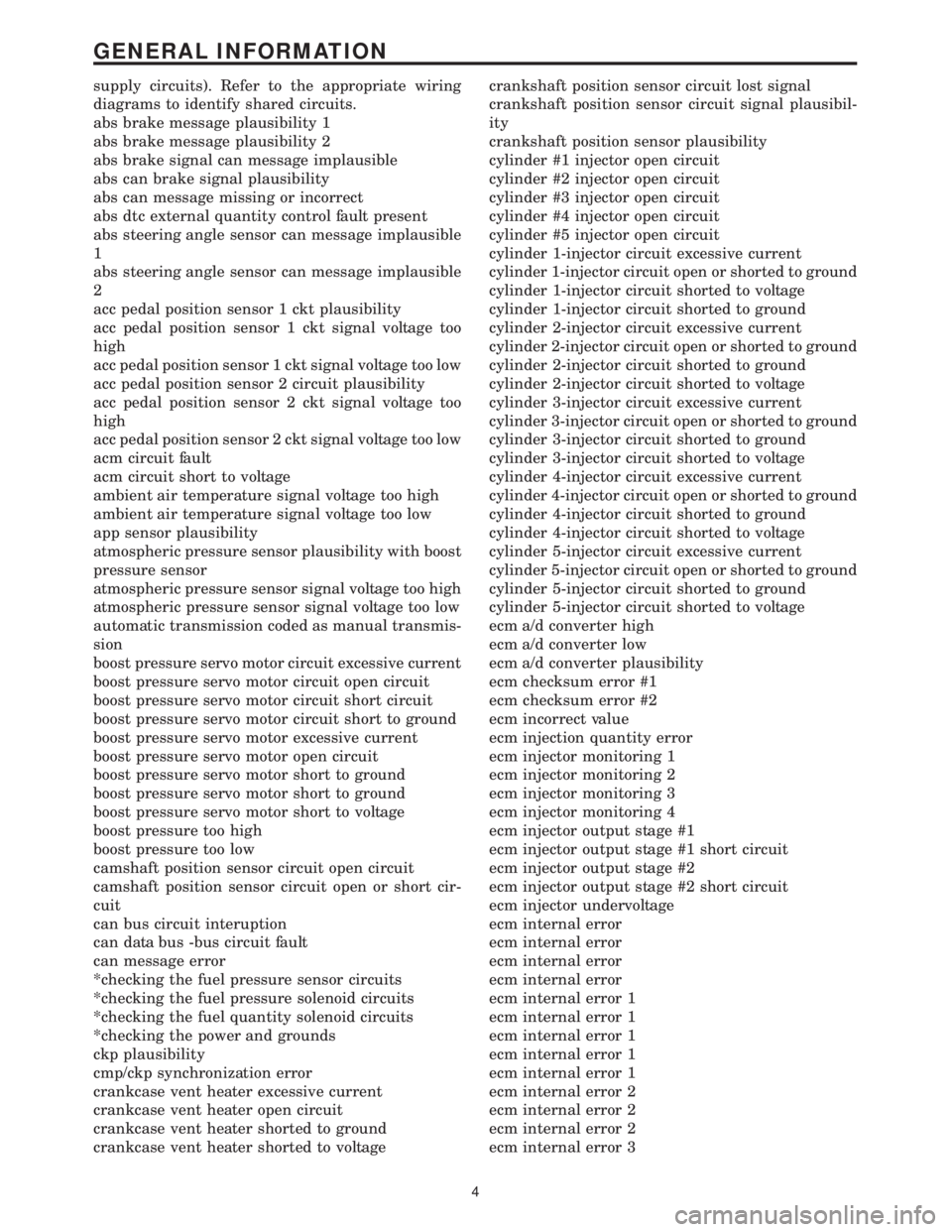
supply circuits). Refer to the appropriate wiring
diagrams to identify shared circuits.
abs brake message plausibility 1
abs brake message plausibility 2
abs brake signal can message implausible
abs can brake signal plausibility
abs can message missing or incorrect
abs dtc external quantity control fault present
abs steering angle sensor can message implausible
1
abs steering angle sensor can message implausible
2
acc pedal position sensor 1 ckt plausibility
acc pedal position sensor 1 ckt signal voltage too
high
acc pedal position sensor 1 ckt signal voltage too low
acc pedal position sensor 2 circuit plausibility
acc pedal position sensor 2 ckt signal voltage too
high
acc pedal position sensor 2 ckt signal voltage too low
acm circuit fault
acm circuit short to voltage
ambient air temperature signal voltage too high
ambient air temperature signal voltage too low
app sensor plausibility
atmospheric pressure sensor plausibility with boost
pressure sensor
atmospheric pressure sensor signal voltage too high
atmospheric pressure sensor signal voltage too low
automatic transmission coded as manual transmis-
sion
boost pressure servo motor circuit excessive current
boost pressure servo motor circuit open circuit
boost pressure servo motor circuit short circuit
boost pressure servo motor circuit short to ground
boost pressure servo motor excessive current
boost pressure servo motor open circuit
boost pressure servo motor short to ground
boost pressure servo motor short to ground
boost pressure servo motor short to voltage
boost pressure too high
boost pressure too low
camshaft position sensor circuit open circuit
camshaft position sensor circuit open or short cir-
cuit
can bus circuit interuption
can data bus -bus circuit fault
can message error
*checking the fuel pressure sensor circuits
*checking the fuel pressure solenoid circuits
*checking the fuel quantity solenoid circuits
*checking the power and grounds
ckp plausibility
cmp/ckp synchronization error
crankcase vent heater excessive current
crankcase vent heater open circuit
crankcase vent heater shorted to ground
crankcase vent heater shorted to voltagecrankshaft position sensor circuit lost signal
crankshaft position sensor circuit signal plausibil-
ity
crankshaft position sensor plausibility
cylinder #1 injector open circuit
cylinder #2 injector open circuit
cylinder #3 injector open circuit
cylinder #4 injector open circuit
cylinder #5 injector open circuit
cylinder 1-injector circuit excessive current
cylinder 1-injector circuit open or shorted to ground
cylinder 1-injector circuit shorted to voltage
cylinder 1-injector circuit shorted to ground
cylinder 2-injector circuit excessive current
cylinder 2-injector circuit open or shorted to ground
cylinder 2-injector circuit shorted to ground
cylinder 2-injector circuit shorted to voltage
cylinder 3-injector circuit excessive current
cylinder 3-injector circuit open or shorted to ground
cylinder 3-injector circuit shorted to ground
cylinder 3-injector circuit shorted to voltage
cylinder 4-injector circuit excessive current
cylinder 4-injector circuit open or shorted to ground
cylinder 4-injector circuit shorted to ground
cylinder 4-injector circuit shorted to voltage
cylinder 5-injector circuit excessive current
cylinder 5-injector circuit open or shorted to ground
cylinder 5-injector circuit shorted to ground
cylinder 5-injector circuit shorted to voltage
ecm a/d converter high
ecm a/d converter low
ecm a/d converter plausibility
ecm checksum error #1
ecm checksum error #2
ecm incorrect value
ecm injection quantity error
ecm injector monitoring 1
ecm injector monitoring 2
ecm injector monitoring 3
ecm injector monitoring 4
ecm injector output stage #1
ecm injector output stage #1 short circuit
ecm injector output stage #2
ecm injector output stage #2 short circuit
ecm injector undervoltage
ecm internal error
ecm internal error
ecm internal error
ecm internal error
ecm internal error 1
ecm internal error 1
ecm internal error 1
ecm internal error 1
ecm internal error 1
ecm internal error 2
ecm internal error 2
ecm internal error 2
ecm internal error 3
4
GENERAL INFORMATION
Page 435 of 2305
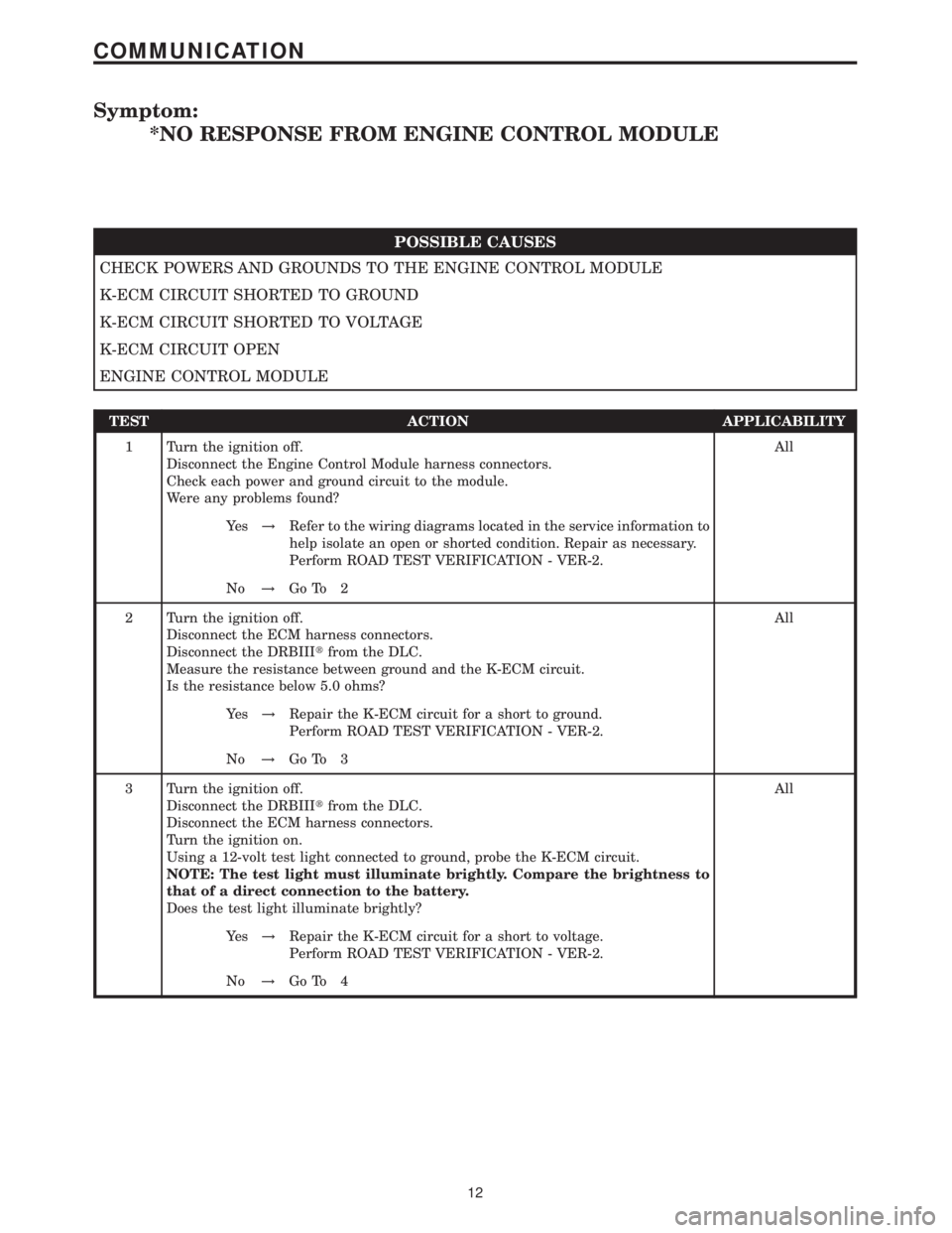
Symptom:
*NO RESPONSE FROM ENGINE CONTROL MODULE
POSSIBLE CAUSES
CHECK POWERS AND GROUNDS TO THE ENGINE CONTROL MODULE
K-ECM CIRCUIT SHORTED TO GROUND
K-ECM CIRCUIT SHORTED TO VOLTAGE
K-ECM CIRCUIT OPEN
ENGINE CONTROL MODULE
TEST ACTION APPLICABILITY
1 Turn the ignition off.
Disconnect the Engine Control Module harness connectors.
Check each power and ground circuit to the module.
Were any problems found?All
Ye s!Refer to the wiring diagrams located in the service information to
help isolate an open or shorted condition. Repair as necessary.
Perform ROAD TEST VERIFICATION - VER-2.
No!Go To 2
2 Turn the ignition off.
Disconnect the ECM harness connectors.
Disconnect the DRBIIItfrom the DLC.
Measure the resistance between ground and the K-ECM circuit.
Is the resistance below 5.0 ohms?All
Ye s!Repair the K-ECM circuit for a short to ground.
Perform ROAD TEST VERIFICATION - VER-2.
No!Go To 3
3 Turn the ignition off.
Disconnect the DRBIIItfrom the DLC.
Disconnect the ECM harness connectors.
Turn the ignition on.
Using a 12-volt test light connected to ground, probe the K-ECM circuit.
NOTE: The test light must illuminate brightly. Compare the brightness to
that of a direct connection to the battery.
Does the test light illuminate brightly?All
Ye s!Repair the K-ECM circuit for a short to voltage.
Perform ROAD TEST VERIFICATION - VER-2.
No!Go To 4
12
COMMUNICATION
Page 437 of 2305
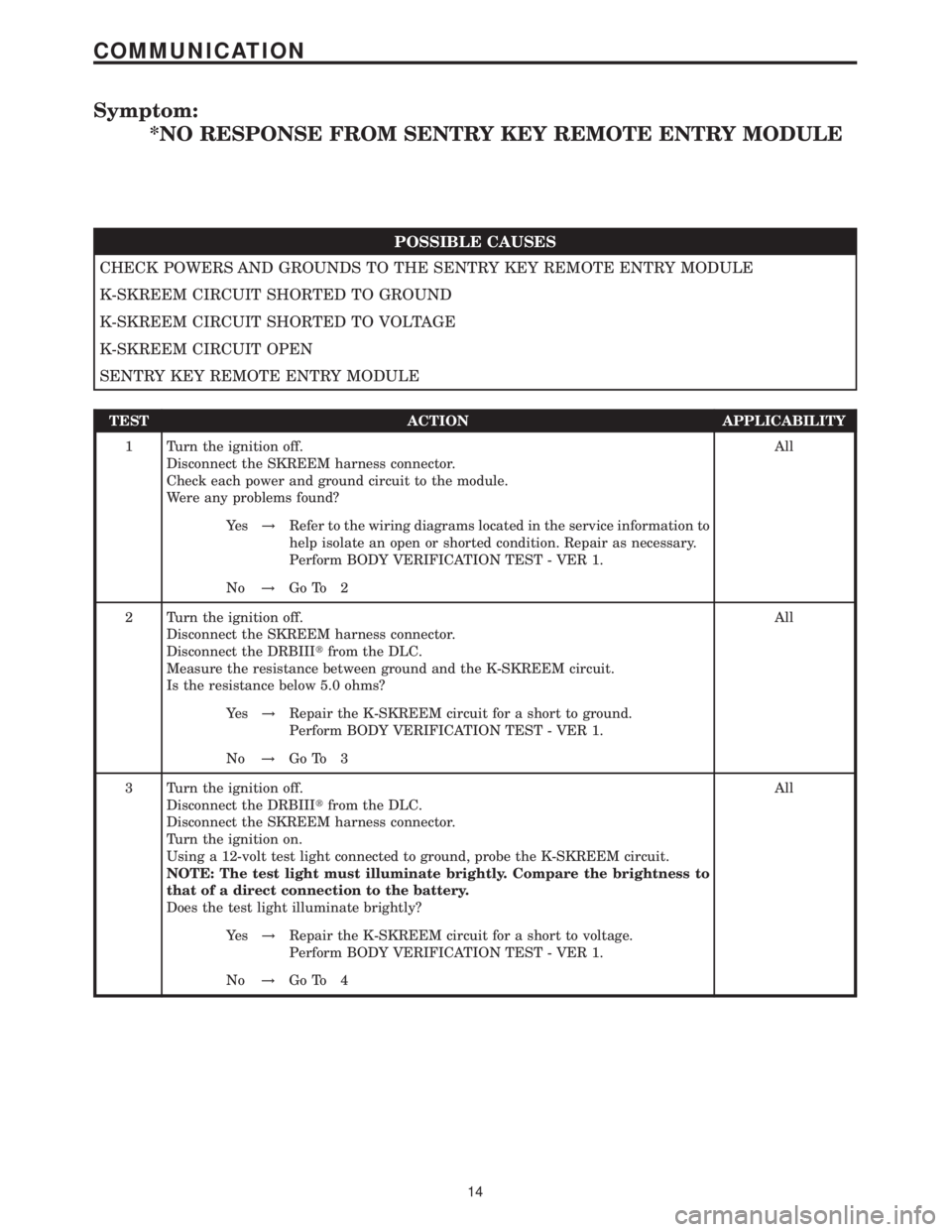
Symptom:
*NO RESPONSE FROM SENTRY KEY REMOTE ENTRY MODULE
POSSIBLE CAUSES
CHECK POWERS AND GROUNDS TO THE SENTRY KEY REMOTE ENTRY MODULE
K-SKREEM CIRCUIT SHORTED TO GROUND
K-SKREEM CIRCUIT SHORTED TO VOLTAGE
K-SKREEM CIRCUIT OPEN
SENTRY KEY REMOTE ENTRY MODULE
TEST ACTION APPLICABILITY
1 Turn the ignition off.
Disconnect the SKREEM harness connector.
Check each power and ground circuit to the module.
Were any problems found?All
Ye s!Refer to the wiring diagrams located in the service information to
help isolate an open or shorted condition. Repair as necessary.
Perform BODY VERIFICATION TEST - VER 1.
No!Go To 2
2 Turn the ignition off.
Disconnect the SKREEM harness connector.
Disconnect the DRBIIItfrom the DLC.
Measure the resistance between ground and the K-SKREEM circuit.
Is the resistance below 5.0 ohms?All
Ye s!Repair the K-SKREEM circuit for a short to ground.
Perform BODY VERIFICATION TEST - VER 1.
No!Go To 3
3 Turn the ignition off.
Disconnect the DRBIIItfrom the DLC.
Disconnect the SKREEM harness connector.
Turn the ignition on.
Using a 12-volt test light connected to ground, probe the K-SKREEM circuit.
NOTE: The test light must illuminate brightly. Compare the brightness to
that of a direct connection to the battery.
Does the test light illuminate brightly?All
Ye s!Repair the K-SKREEM circuit for a short to voltage.
Perform BODY VERIFICATION TEST - VER 1.
No!Go To 4
14
COMMUNICATION
Page 558 of 2305
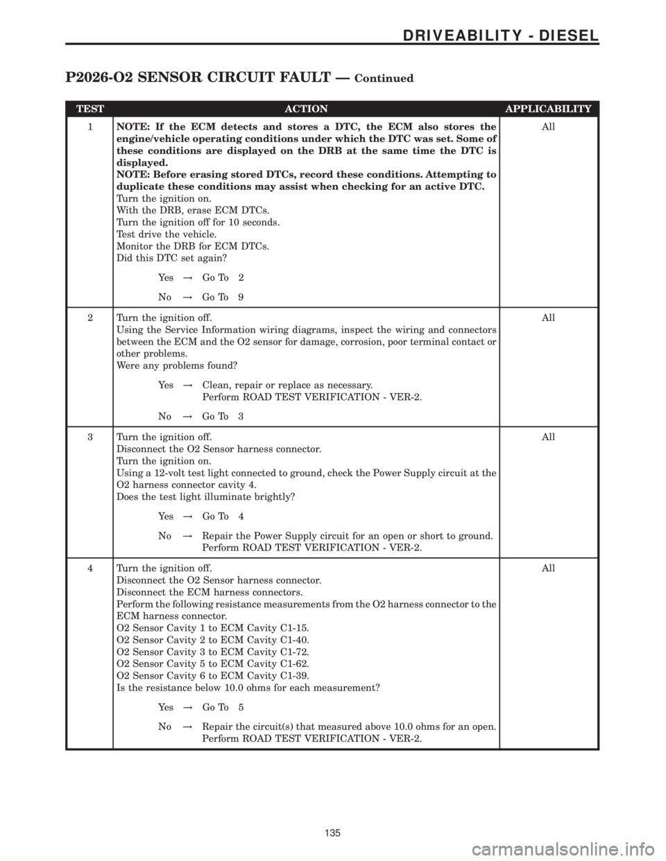
TEST ACTION APPLICABILITY
1NOTE: If the ECM detects and stores a DTC, the ECM also stores the
engine/vehicle operating conditions under which the DTC was set. Some of
these conditions are displayed on the DRB at the same time the DTC is
displayed.
NOTE: Before erasing stored DTCs, record these conditions. Attempting to
duplicate these conditions may assist when checking for an active DTC.
Turn the ignition on.
With the DRB, erase ECM DTCs.
Turn the ignition off for 10 seconds.
Test drive the vehicle.
Monitor the DRB for ECM DTCs.
Did this DTC set again?All
Ye s!Go To 2
No!Go To 9
2 Turn the ignition off.
Using the Service Information wiring diagrams, inspect the wiring and connectors
between the ECM and the O2 sensor for damage, corrosion, poor terminal contact or
other problems.
Were any problems found?All
Ye s!Clean, repair or replace as necessary.
Perform ROAD TEST VERIFICATION - VER-2.
No!Go To 3
3 Turn the ignition off.
Disconnect the O2 Sensor harness connector.
Turn the ignition on.
Using a 12-volt test light connected to ground, check the Power Supply circuit at the
O2 harness connector cavity 4.
Does the test light illuminate brightly?All
Ye s!Go To 4
No!Repair the Power Supply circuit for an open or short to ground.
Perform ROAD TEST VERIFICATION - VER-2.
4 Turn the ignition off.
Disconnect the O2 Sensor harness connector.
Disconnect the ECM harness connectors.
Perform the following resistance measurements from the O2 harness connector to the
ECM harness connector.
O2 Sensor Cavity 1 to ECM Cavity C1-15.
O2 Sensor Cavity 2 to ECM Cavity C1-40.
O2 Sensor Cavity 3 to ECM Cavity C1-72.
O2 Sensor Cavity 5 to ECM Cavity C1-62.
O2 Sensor Cavity 6 to ECM Cavity C1-39.
Is the resistance below 10.0 ohms for each measurement?All
Ye s!Go To 5
No!Repair the circuit(s) that measured above 10.0 ohms for an open.
Perform ROAD TEST VERIFICATION - VER-2.
135
DRIVEABILITY - DIESEL
P2026-O2 SENSOR CIRCUIT FAULT ÐContinued
Page 561 of 2305
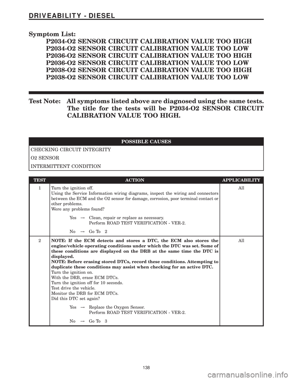
Symptom List:
P2034-O2 SENSOR CIRCUIT CALIBRATION VALUE TOO HIGH
P2034-O2 SENSOR CIRCUIT CALIBRATION VALUE TOO LOW
P2036-O2 SENSOR CIRCUIT CALIBRATION VALUE TOO HIGH
P2036-O2 SENSOR CIRCUIT CALIBRATION VALUE TOO LOW
P2038-O2 SENSOR CIRCUIT CALIBRATION VALUE TOO HIGH
P2038-O2 SENSOR CIRCUIT CALIBRATION VALUE TOO LOW
Test Note: All symptoms listed above are diagnosed using the same tests.
The title for the tests will be P2034-O2 SENSOR CIRCUIT
CALIBRATION VALUE TOO HIGH.
POSSIBLE CAUSES
CHECKING CIRCUIT INTEGRITY
O2 SENSOR
INTERMITTENT CONDITION
TEST ACTION APPLICABILITY
1 Turn the ignition off.
Using the Service Information wiring diagrams, inspect the wiring and connectors
between the ECM and the O2 sensor for damage, corrosion, poor terminal contact or
other problems.
Were any problems found?All
Ye s!Clean, repair or replace as necessary.
Perform ROAD TEST VERIFICATION - VER-2.
No!Go To 2
2NOTE: If the ECM detects and stores a DTC, the ECM also stores the
engine/vehicle operating conditions under which the DTC was set. Some of
these conditions are displayed on the DRB at the same time the DTC is
displayed.
NOTE: Before erasing stored DTCs, record these conditions. Attempting to
duplicate these conditions may assist when checking for an active DTC.
Turn the ignition on.
With the DRB, erase ECM DTCs.
Turn the ignition off for 10 seconds.
Test drive the vehicle.
Monitor the DRB for ECM DTCs.
Did this DTC set again?All
Ye s!Replace the Oxygen Sensor.
Perform ROAD TEST VERIFICATION - VER-2.
No!Go To 3
138
DRIVEABILITY - DIESEL
Page 660 of 2305
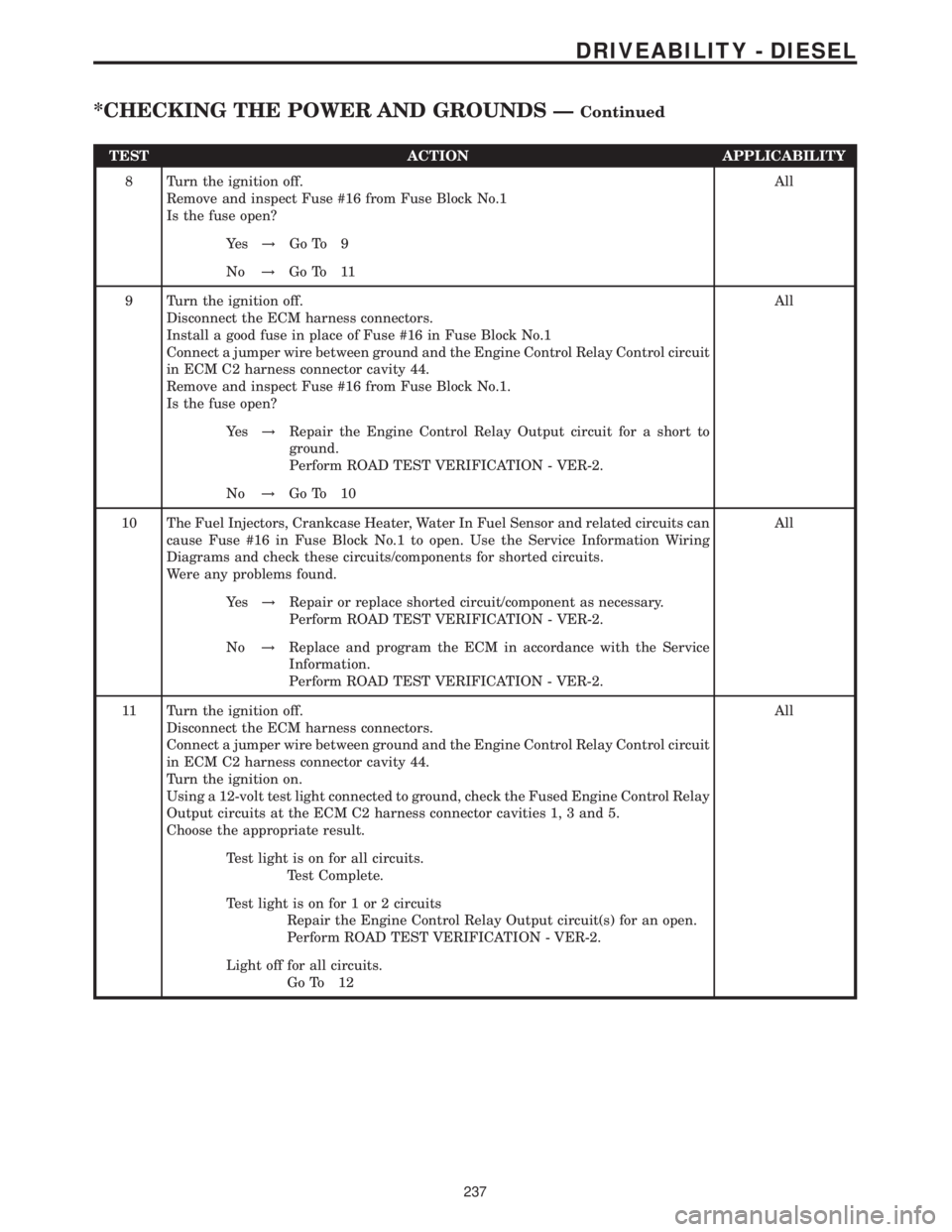
TEST ACTION APPLICABILITY
8 Turn the ignition off.
Remove and inspect Fuse #16 from Fuse Block No.1
Is the fuse open?All
Ye s!Go To 9
No!Go To 11
9 Turn the ignition off.
Disconnect the ECM harness connectors.
Install a good fuse in place of Fuse #16 in Fuse Block No.1
Connect a jumper wire between ground and the Engine Control Relay Control circuit
in ECM C2 harness connector cavity 44.
Remove and inspect Fuse #16 from Fuse Block No.1.
Is the fuse open?All
Ye s!Repair the Engine Control Relay Output circuit for a short to
ground.
Perform ROAD TEST VERIFICATION - VER-2.
No!Go To 10
10 The Fuel Injectors, Crankcase Heater, Water In Fuel Sensor and related circuits can
cause Fuse #16 in Fuse Block No.1 to open. Use the Service Information Wiring
Diagrams and check these circuits/components for shorted circuits.
Were any problems found.All
Ye s!Repair or replace shorted circuit/component as necessary.
Perform ROAD TEST VERIFICATION - VER-2.
No!Replace and program the ECM in accordance with the Service
Information.
Perform ROAD TEST VERIFICATION - VER-2.
11 Turn the ignition off.
Disconnect the ECM harness connectors.
Connect a jumper wire between ground and the Engine Control Relay Control circuit
in ECM C2 harness connector cavity 44.
Turn the ignition on.
Using a 12-volt test light connected to ground, check the Fused Engine Control Relay
Output circuits at the ECM C2 harness connector cavities 1, 3 and 5.
Choose the appropriate result.All
Test light is on for all circuits.
Test Complete.
Test light is on for 1 or 2 circuits
Repair the Engine Control Relay Output circuit(s) for an open.
Perform ROAD TEST VERIFICATION - VER-2.
Light off for all circuits.
Go To 12
237
DRIVEABILITY - DIESEL
*CHECKING THE POWER AND GROUNDS ÐContinued
Page 854 of 2305
CHIME / BUZZER
TABLE OF CONTENTS
page page
CHIME/BUZZER
DESCRIPTION..........................1
OPERATION............................1DIAGNOSIS AND TESTING - CHIME
WARNING SYSTEM.....................2
CHIME / BUZZER
DESCRIPTION
A chime warning system is standard factory-in-
stalled equipment. The chime warning system uses a
chime tone generator and a contactless relay that are
soldered onto the electronic circuit board inside the
ElectroMechanical Instrument Cluster (EMIC) to
provide audible indications of various vehicle condi-
tions that may require the attention of the vehicle
operator or occupants. The microprocessor-based
EMIC utilizes electronic messages received from
other modules in the vehicle over the Controller Area
Network (CAN) data bus network along with hard
wired inputs to the cluster to monitor many sensors
and switches throughout the vehicle. In response to
those inputs, the circuitry and internal programming
of the EMIC allow it to control audible outputs that
are produced through its on-board chime tone gener-
ator and contactless relay.
The EMIC circuitry and its chime tone generator
are capable of producing the following audible out-
puts:
²Single Chime Tone- A single, extended ªbeep-
likeº chime tone is issued as a seat belt reminder.
²Fast Rate Repetitive Chime Tone- Repeated
ªbeep-likeº tones that are issued at a fast rate as an
audible alert and to support various visual warnings.
²Slow Rate Repetitive Click Tone- Repeated
ªclick-likeº tones that are issued at a slow rate to
emulate turn signal and hazard flasher operation.
²Fast Rate Repetitive Click Tone- Repeated
ªclick-likeº tones that are issued at a fast rate to
emulate turn signal flasher operation with a bulb
out.
Hard wired circuitry connects the EMIC and the
various chime warning switch and sensor inputs to
their respective modules and to each other through
the electrical system of the vehicle. These hard wired
circuits are integral to the vehicle wire harness,
which is routed throughout the vehicle and retained
by many different methods. These circuits may be
connected to each other, to the vehicle electrical sys-
tem and to the EMIC through the use of a combina-
tion of soldered splices, splice block connectors, andmany different types of wire harness terminal con-
nectors and insulators. Refer to the appropriate wir-
ing information. The wiring information includes
wiring diagrams, proper wire and connector repair
procedures, further details on wire harness routing
and retention, as well as pin-out and location views
for the various wire harness connectors, splices and
grounds.
The EMIC chime tone generator and contactless
relay cannot be adjusted or repaired. If the chime
tone generator or contactless relay are damaged or
faulty, the entire EMIC unit must be replaced.
OPERATION
The chime warning system components operate on
battery current received through a non-switched
fused B(+) circuit so that the system may operate
regardless of the ignition switch position. The Elec-
troMechanical Instrument Cluster (EMIC) also mon-
itors the ignition switch position so that some chime
features will only occur with ignition switch in the
On position, while others occur regardless of the igni-
tion switch position.
The chime warning system provides an audible
indication to the vehicle operator or occupants under
the following conditions:
²Engine Oil Level Low Warning- Each time
the ignition switch is turned to the On position, the
EMIC chime tone generator will generate a fast rate
repetitive chime tone if electronic messages are
received over the Controller Area Network (CAN)
data bus from the Engine Control Module (ECM)
indicating that the engine level is too low. The ECM
uses internal programming and hard wired inputs
from the engine oil level and temperature sensor to
determine the engine oil level. This audible warning
occurs in concert with the visual warning provided by
the multi-function indicator in the cluster.
²Fasten Seat Belt Reminder- Each time the
ignition switch is turned to the On position, the
EMIC chime tone generator will generate a single
extended chime tone for a duration of about six sec-
onds, or until the driver side front seat belt is fas-
tened, whichever occurs first. The EMIC uses
internal programming and a hard wired input from
the driver side front seat belt switch to determine
VACHIME/BUZZER 8B - 1
Page 881 of 2305
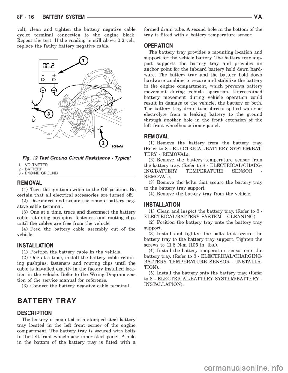
volt, clean and tighten the battery negative cable
eyelet terminal connection to the engine block.
Repeat the test. If the reading is still above 0.2 volt,
replace the faulty battery negative cable.
REMOVAL
(1) Turn the ignition switch to the Off position. Be
certain that all electrical accessories are turned off.
(2) Disconnect and isolate the remote battery neg-
ative cable terminal.
(3) One at a time, trace and disconnect the battery
cable retaining pushpins, fasteners and routing clips
until the cables are free from the vehicle.
(4) Feed the battery cable assembly out of the
vehicle.
INSTALLATION
(1) Position the battery cable in the vehicle.
(2) One at a time, install the battery cable retain-
ing pushpins, fasteners and routing clips until the
cable is installed exactly in the factory installed loca-
tion in the vehicle. Refer to the Wiring Diagram sec-
tion of the service manual for reference.
(3) Connect the battery negative cable terminal.
BATTERY TRAY
DESCRIPTION
The battery is mounted in a stamped steel battery
tray located in the left front corner of the engine
compartment. The battery tray is secured with bolts
to the left front wheelhouse inner steel panel. A hole
in the bottom of the battery tray is fitted with aformed drain tube. A second hole in the bottom of the
tray is fitted with a battery temperature sensor.
OPERATION
The battery tray provides a mounting location and
support for the vehicle battery. The battery tray sup-
port supports the battery tray and provides an
anchor point for the inboard battery hold down hard-
ware. The battery tray and the battery hold down
hardware combine to secure and stabilize the battery
in the engine compartment, which prevents battery
movement during vehicle operation. Unrestrained
battery movement during vehicle operation could
result in damage to the vehicle, the battery or both.
The battery tray drain tube directs spilled water or
electrolyte from a leaking battery to the ground
through another hole in the front extension of the
left front wheelhouse inner panel.
REMOVAL
(1) Remove the battery from the battery tray.
(Refer to 8 - ELECTRICAL/BATTERY SYSTEM/BAT-
TERY - REMOVAL).
(2) Remove the battery temperature sensor from
the battery tray. (Refer to 8 - ELECTRICAL/CHARG-
ING/BATTERY TEMPERATURE SENSOR -
REMOVAL).
(3) Remove the bolts that secure the battery tray
to the battery tray support.
(4) Remove the battery tray from the vehicle.
INSTALLATION
(1) Clean and inspect the battery tray. (Refer to 8 -
ELECTRICAL/BATTERY SYSTEM - CLEANING).
(2) Position the battery tray onto the battery tray
support.
(3) Install and tighten the bolts that secure the
battery tray to the battery tray support. Tighten the
screws to 11.8 N´m (105 in. lbs.).
(4) Install the battery temperature sensor onto the
battery tray. (Refer to 8 - ELECTRICAL/CHARGING/
BATTERY TEMPERATURE SENSOR - INSTALLA-
TION).
(5) Install the battery onto the battery tray. (Refer
to 8 - ELECTRICAL/BATTERY SYSTEM/BATTERY -
INSTALLATION).
Fig. 12 Test Ground Circuit Resistance - Typical
1 - VOLTMETER
2 - BATTERY
3 - ENGINE GROUND
8F - 16 BATTERY SYSTEMVA