headlamp MERCEDES-BENZ SPRINTER 2006 Service Manual
[x] Cancel search | Manufacturer: MERCEDES-BENZ, Model Year: 2006, Model line: SPRINTER, Model: MERCEDES-BENZ SPRINTER 2006Pages: 2305, PDF Size: 48.12 MB
Page 284 of 2305
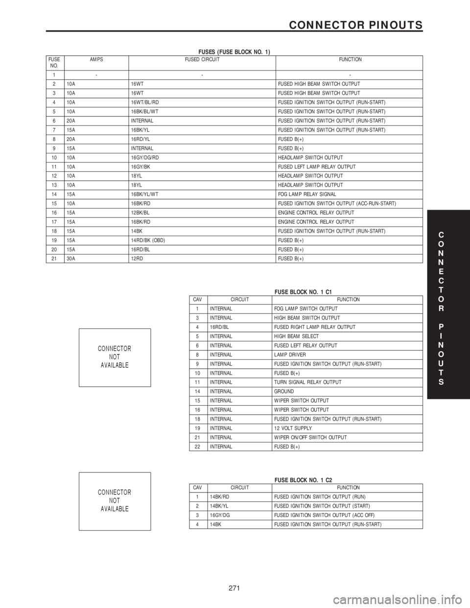
FUSES (FUSE BLOCK NO. 1)FUSE
NO.AMPS FUSED CIRCUIT FUNCTION
1- - -
2 10A 16WT FUSED HIGH BEAM SWITCH OUTPUT
3 10A 16WT FUSED HIGH BEAM SWITCH OUTPUT
4 10A 16WT/BL/RD FUSED IGNITION SWITCH OUTPUT (RUN-START)
5 10A 16BK/BL/WT FUSED IGNITION SWITCH OUTPUT (RUN-START)
6 20A INTERNAL FUSED IGNITION SWITCH OUTPUT (RUN-START)
7 15A 16BK/YL FUSED IGNITION SWITCH OUTPUT (RUN-START)
8 20A 16RD/YL FUSED B(+)
9 15A INTERNAL FUSED B(+)
10 10A 16GY/DG/RD HEADLAMP SWITCH OUTPUT
11 10A 16GY/BK FUSED LEFT LAMP RELAY OUTPUT
12 10A 18YL HEADLAMP SWITCH OUTPUT
13 10A 18YL HEADLAMP SWITCH OUTPUT
14 15A 16BK/YL/WT FOG LAMP RELAY SIGNAL
15 10A 16BK/RD FUSED IGNITION SWITCH OUTPUT (ACC-RUN-START)
16 15A 12BK/BL ENGINE CONTROL RELAY OUTPUT
17 15A 16BK/RD ENGINE CONTROL RELAY OUTPUT
18 15A 14BK FUSED IGNITION SWITCH OUTPUT (RUN-START)
19 15A 14RD/BK (OBD) FUSED B(+)
20 15A 16RD/BL FUSED B(+)
21 30A 12RD FUSED B(+)
FUSE BLOCK NO. 1 C1CAV CIRCUIT FUNCTION
1 INTERNAL FOG LAMP SWITCH OUTPUT
3 INTERNAL HIGH BEAM SWITCH OUTPUT
4 16RD/BL FUSED RIGHT LAMP RELAY OUTPUT
5 INTERNAL HIGH BEAM SELECT
6 INTERNAL FUSED LEFT RELAY OUTPUT
8 INTERNAL LAMP DRIVER
9 INTERNAL FUSED IGNITION SWITCH OUTPUT (RUN-START)
10 INTERNAL FUSED B(+)
11 INTERNAL TURN SIGNAL RELAY OUTPUT
14 INTERNAL GROUND
15 INTERNAL WIPER SWITCH OUTPUT
16 INTERNAL WIPER SWITCH OUTPUT
18 INTERNAL FUSED IGNITION SWITCH OUTPUT (RUN-START)
19 INTERNAL 12 VOLT SUPPLY
21 INTERNAL WIPER ON/OFF SWITCH OUTPUT
22 INTERNAL FUSED B(+)
FUSE BLOCK NO. 1 C2CAV CIRCUIT FUNCTION
1 14BK/RD FUSED IGNITION SWITCH OUTPUT (RUN)
2 14BK/YL FUSED IGNITION SWITCH OUTPUT (START)
3 16GY/DG FUSED IGNITION SWITCH OUTPUT (ACC OFF)
4 14BK FUSED IGNITION SWITCH OUTPUT (RUN-START)
C
O
N
N
E
C
T
O
R
P
I
N
O
U
T
S
271
CONNECTOR PINOUTS
Page 285 of 2305
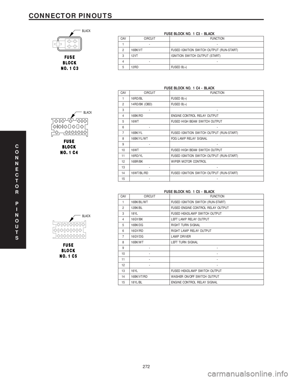
FUSE BLOCK NO. 1 C3 - BLACKCAV CIRCUIT FUNCTION
1- -
2 16BK/VT FUSED IGNITION SWITCH OUTPUT (RUN-START)
3 12VT IGNITION SWITCH OUTPUT (START)
4- -
5 12RD FUSED B(+)
FUSE BLOCK NO. 1 C4 - BLACKCAV CIRCUIT FUNCTION
1 16RD/BL FUSED B(+)
2 14RD/BK (OBD) FUSED B(+)
3- -
4 16BK/RD ENGINE CONTROL RELAY OUTPUT
5 16WT FUSED HIGH BEAM SWITCH OUTPUT
6- -
7 16BK/YL FUSED IGNITION SWITCH OUTPUT (RUN-START)
8 16BK/YL/WT FOG LAMP RELAY SIGNAL
9- -
10 16WT FUSED HIGH BEAM SWITCH OUTPUT
11 16RD/YL FUSED IGNITION SWITCH OUTPUT (RUN-START)
12 16BR/BK WIPER MOTOR CONTROL
13 - -
14 16WT/BL/RD FUSED IGNITION SWITCH OUTPUT (RUN-START)
15 - -
FUSE BLOCK NO. 1 C5 - BLACKCAV CIRCUIT FUNCTION
1 16BK/BL/WT FUSED IGNITION SWITCH (RUN-START)
2 12BK/BL FUSED ENGINE CONTROL RELAY OUTPUT
3 18YL FUSED HEADLAMP SWITCH OUTPUT
4 16GY/BK LEFT LAMP RELAY OUTPUT
5 16BK/DG RIGHT TURN SIGNAL
6 16GY/RD RIGHT LAMP RELAY OUTPUT
7 16GY/DG LAMP DRIVER
8 16BK/WT LEFT TURN SIGNAL
9- -
10 - -
11 - -
12 - -
13 16YL FUSED HEADLAMP SWITCH OUTPUT
14 16BK/VT/RD WASHER ON/OFF SWITCH OUTPUT
15 18YL/BL ENGINE CONTROL RELAY SIGNAL
C
O
N
N
E
C
T
O
R
P
I
N
O
U
T
S
272
CONNECTOR PINOUTS
Page 688 of 2305
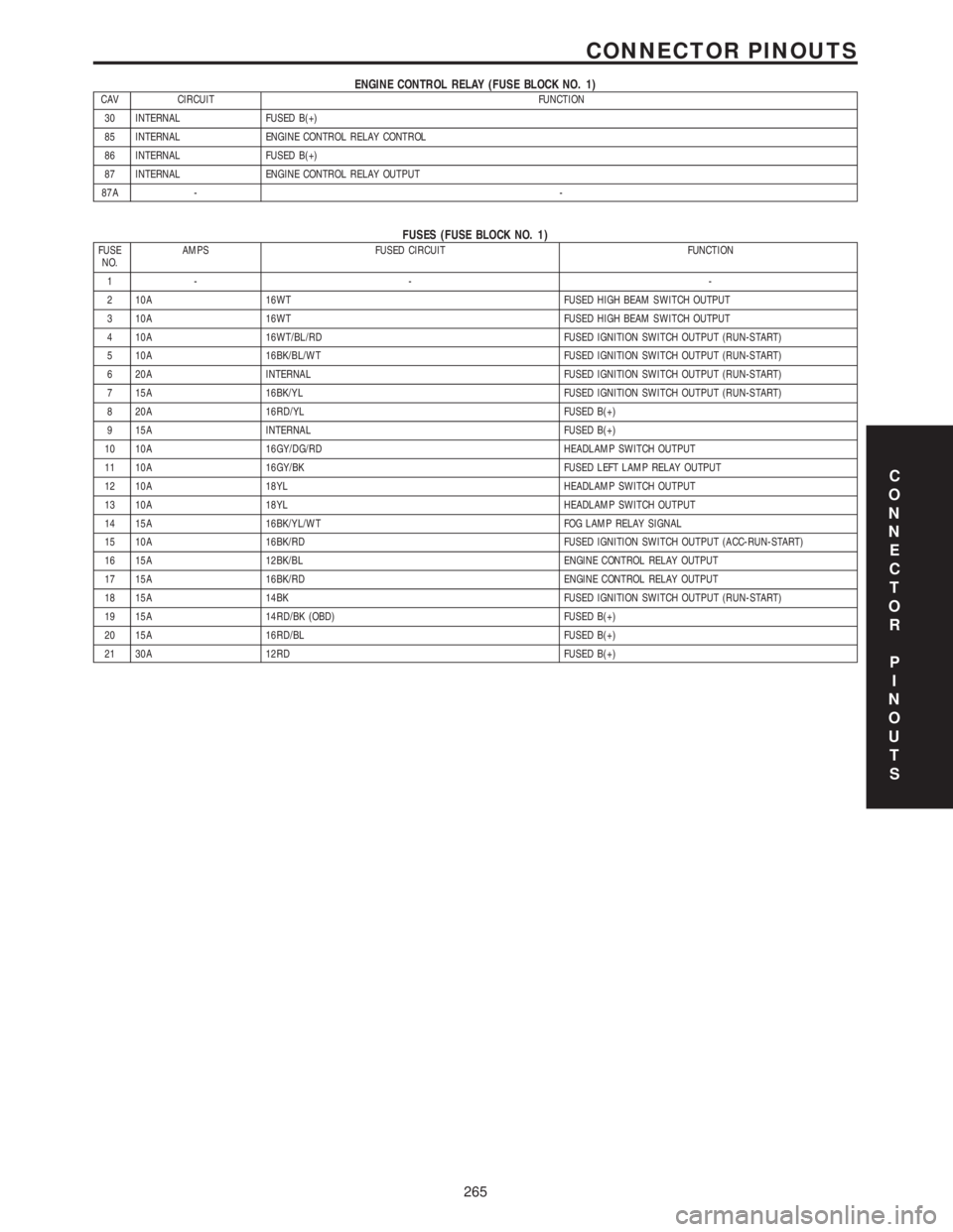
ENGINE CONTROL RELAY (FUSE BLOCK NO. 1)CAV CIRCUIT FUNCTION
30 INTERNAL FUSED B(+)
85 INTERNAL ENGINE CONTROL RELAY CONTROL
86 INTERNAL FUSED B(+)
87 INTERNAL ENGINE CONTROL RELAY OUTPUT
87A --
FUSES (FUSE BLOCK NO. 1)FUSE
NO.AMPS FUSED CIRCUIT FUNCTION
1- - -
2 10A 16WT FUSED HIGH BEAM SWITCH OUTPUT
3 10A 16WT FUSED HIGH BEAM SWITCH OUTPUT
4 10A 16WT/BL/RD FUSED IGNITION SWITCH OUTPUT (RUN-START)
5 10A 16BK/BL/WT FUSED IGNITION SWITCH OUTPUT (RUN-START)
6 20A INTERNAL FUSED IGNITION SWITCH OUTPUT (RUN-START)
7 15A 16BK/YL FUSED IGNITION SWITCH OUTPUT (RUN-START)
8 20A 16RD/YL FUSED B(+)
9 15A INTERNAL FUSED B(+)
10 10A 16GY/DG/RD HEADLAMP SWITCH OUTPUT
11 10A 16GY/BK FUSED LEFT LAMP RELAY OUTPUT
12 10A 18YL HEADLAMP SWITCH OUTPUT
13 10A 18YL HEADLAMP SWITCH OUTPUT
14 15A 16BK/YL/WT FOG LAMP RELAY SIGNAL
15 10A 16BK/RD FUSED IGNITION SWITCH OUTPUT (ACC-RUN-START)
16 15A 12BK/BL ENGINE CONTROL RELAY OUTPUT
17 15A 16BK/RD ENGINE CONTROL RELAY OUTPUT
18 15A 14BK FUSED IGNITION SWITCH OUTPUT (RUN-START)
19 15A 14RD/BK (OBD) FUSED B(+)
20 15A 16RD/BL FUSED B(+)
21 30A 12RD FUSED B(+)
C
O
N
N
E
C
T
O
R
P
I
N
O
U
T
S
265
CONNECTOR PINOUTS
Page 708 of 2305
FASTENER IDENTIFICATION
DESCRIPTION
The SAE bolt strength grades range from grade 2
to grade 8. The higher the grade number, the greater
the bolt strength. Identification is determined by the
line marks on the top of each bolt head. The actual
bolt strength grade corresponds to the number of line
marks plus 2. The most commonly used metric bolt
strength classes are 9.8 and 10.9. The metric
strength class identification number is imprinted on
the head of the bolt. The higher the class number,
the greater the bolt strength. Some metric nuts are
imprinted with a single-digit strength class on the
nut face. Refer to the Fastener Identification and
Fastener Strength Charts (Fig. 2) and (Fig. 3).
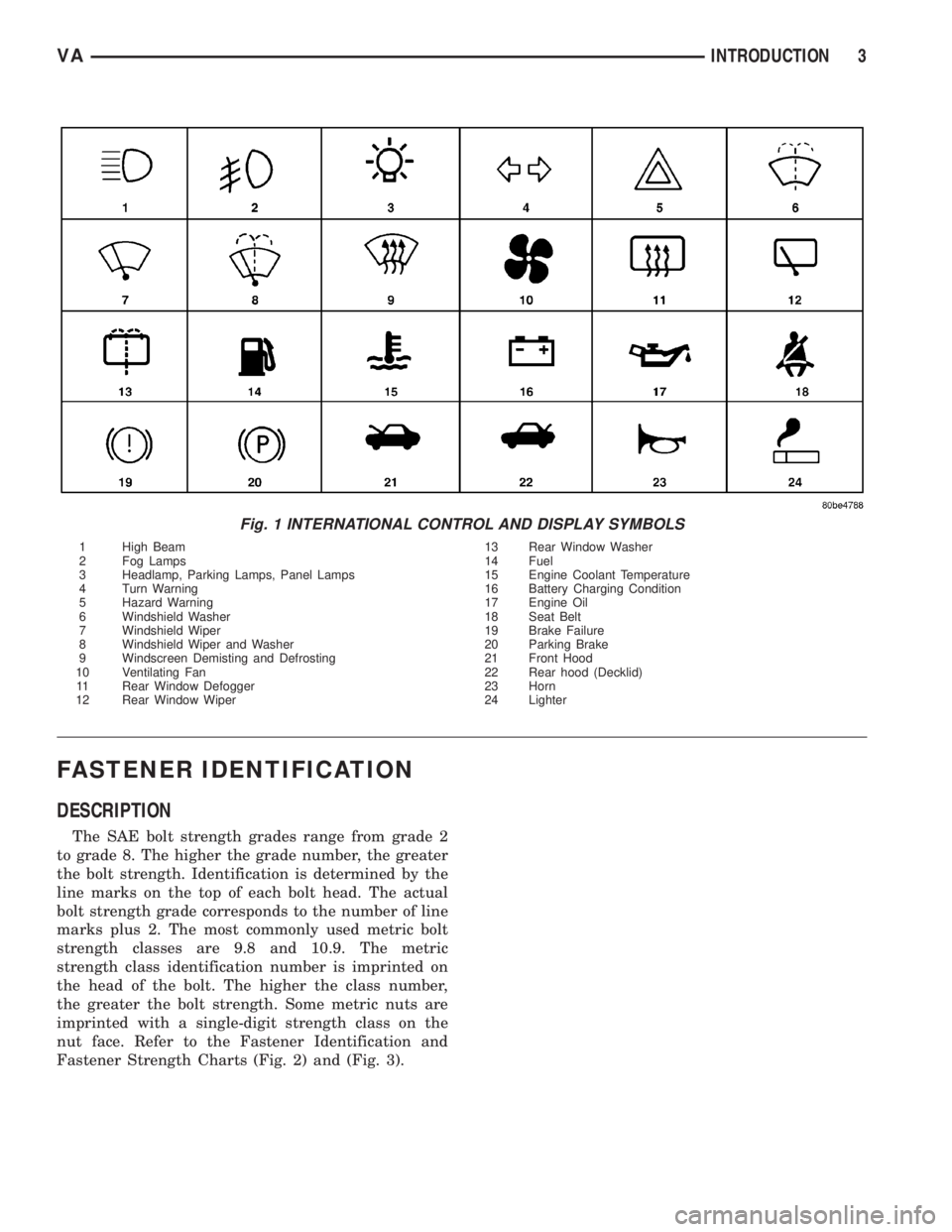
Fig. 1 INTERNATIONAL CONTROL AND DISPLAY SYMBOLS
1 High Beam 13 Rear Window Washer
2 Fog Lamps 14 Fuel
3 Headlamp, Parking Lamps, Panel Lamps 15 Engine Coolant Temperature
4 Turn Warning 16 Battery Charging Condition
5 Hazard Warning 17 Engine Oil
6 Windshield Washer 18 Seat Belt
7 Windshield Wiper 19 Brake Failure
8 Windshield Wiper and Washer 20 Parking Brake
9 Windscreen Demisting and Defrosting 21 Front Hood
10 Ventilating Fan 22 Rear hood (Decklid)
11 Rear Window Defogger 23 Horn
12 Rear Window Wiper 24 Lighter
VAINTRODUCTION 3
Page 723 of 2305
effect panels. If necessary, remove the wheels from
the lifted end of the vehicle and lower the vehicle
closer to the ground, to increase the ground clearance
at the opposite end of the vehicle. Install lug nuts on
wheel attaching studs to retain brake drums.
RAMP ANGLE
If a vehicle with flat-bed towing equipment is used,
the approach ramp angle should not exceed 15
degrees.
TOWING WHEN KEYS ARE NOT AVAILABLE
When the vehicle is locked and keys are not avail-
able, use a flat bed hauler. A Wheel-lift or Sling-type
device can be used provided all the wheels are lifted
off the ground using tow dollies.
MAINTENANCE SCHEDULES
DESCRIPTION
The use of special lubricant additives is not recom-
mended. The use of such additives may affect the
warranty rights. With regard to legal stipulations
concerning emissions control, please note that
engines have to be serviced and adjusted in accor-
dance with special instructions and using special
measuring equipment. Modifications to or interfer-
ence with the emissions control systems are not per-
missible.
MAINTENANCE - WITHOUT ASSYST MAINTE-
NANCE COMPUTER
Maintenance Intervals
²Oil service ±Normal Operationevery 10,000
miles or 16,000 km or 12 months.
²Maintenance service every 30,000 miles or
48,000 km.
Additional work must be carried out at yearly
intervals.
MAINTENANCE - WITH ASSYST MAINTENANCE
COMPUTER
ASSYST provides information on the best possible
timing for maintenance work.
When the next maintenance service is due, this
will be indicated in the multi-function display with
the wrench icon symbol displayed in km/miles or
days.
²One wrench icon showing indicates Oil Service
is necessary.
²Two wrench icons showing indicates Mainte-
nance Service is necessary ± displayed in km/miles or
days.
If the display shows the number of days, a clock
symbol will also appear in the multi-function display.You should have the maintenance performed
within the stated period/distance.
The service indicator will be reset after an oil ser-
vice and/or maintenance service has been performed.
REGULAR CHECK - UPS
To maintain the safe operation of the vehicle, it is
recommended that the following tasks be performed
on a regular basis (i.e. weekly or whenever the vehi-
cle is refueled). Check:
²Engine oil level
²Brake system - fluid level
²Battery - acid level
²Windshield washer system and headlamp clean-
ing system - fluid level
²Mechanical assemblies (e.g. engine, transmis-
sion, etc.) - check for leaks
²Condition of tires and tires pressures
²All exterior lights
SPECIAL MAINTENANCE REQUIREMENTS
If bodies built by manufacturers other than
DaimlerChrysler Corporation are fitted to the vehi-
cle, the maintenance requirements and lubrication
intervals specified by the body manufacturer must be
adhered to, in addition to all standard maintenance
requirements.
Coolant
Corrosion inhibitor/antifreeze concentration in the
coolant should be checked before the onset of winter
(once year in countries with high prevailing temper-
atures).
Replace the coolant every five years or 100,000
miles.
Dust Filter for Heating / Ventilation Replacement
The dust filter and the tailgate interior filter are to
be renewed during routine maintenance service. If
operating conditions are dusty, these filters should be
renewed more frequently.
ENGINE OIL CHANGE AND FILTER REPLACEMENT
At a minimum, change the engine oil and oil filter
once a year ± even if the vehicle mileage per year is
extremely low. For standard oil service schedules
refer to the chapter oil service and maintenance ser-
vice.
Once a Year
Select the viscosity of the engine oil (SAE classes)
according to the outside air temperature.
Only use engine oil approved by DaimlerChrysler
Corporation if following the ASSYST system guide-
lines.
0 - 8 LUBRICATION & MAINTENANCEVA
Page 724 of 2305
SCOPE OF WORK FOR MAINTENANCE SERVICE
Oil Service
²Engine: Oil change and filter replacement
Check fluid levels of the following system, refill as neces-
sary.
²If fluid is lost, trace and eliminate cause - as a
separate order.
²Power-assisted steering
Lubrication work:
²Trailer tow hitch (original equipment)
Maintenance
²ASSYST maintenance computer reset
Function check
²Signalling system, warning and indicator lamps
²Headlamps, exterior lighting
²Windshield wipers, windshield washer system
Check for leaks and damage
²Check for abrasion points and ensure that lines
are correctly routed!
²All lines and hoses, sensor cables
²Rubber boots on front axle drive shafts, rubber
boots on front axle suspension ball joints, shock
absorbers
²Check fluid levels for the following systems, cor-
rect as necessary
NOTE: Should there be a loss of fluid which cannot
be explained by regular use, trace and eliminate the
cause.
²Engine cooling system. Check corrosion inhibi-
tor/antifreeze, refill as necessary.
²Hydraulic brake system
²Battery
²Windshield washer system
Engine
²Fuel filter renewal - Every oil service
²Air cleaner with maintenance indicator:
²Check degree of contamination.
²Air cleaner filter element renewed as necessary.
Chassis and body
²Trailer coupling: Check operation, play and
retaining fixtures
²Secondary rubber springs: Visual check
²Tire pressures: Correct as necessary, including
spare tire
²Check thickness of brake pads
²Brake test
²Check condition of steering mechanism
²Heating/ventilation dust filter renewal
ADDITIONAL MAINTENANCE WORK
Automatic transmission once only at 80,000 miles / 128000
km
²Oil and filter change
During every second maintenance service
²Air cleaner without maintenance indicator:
²Air cleaner filter element renewal
²Check poly-V-belt for wear and signs of damage
During every fourth maintenance service
²Change rear axle fluid
ADDITIONAL MAINTENANCE WORK AFTER YEARS
Every 2 years
²Change brake fluid.
Every 3 years
²Air cleaner filter element renewal (note installa-
tion date)
Every 15 years or 100,000 miles
²Coolant renewal
²Note coolant composition
INTERNATIONAL SYMBOLS
DESCRIPTION
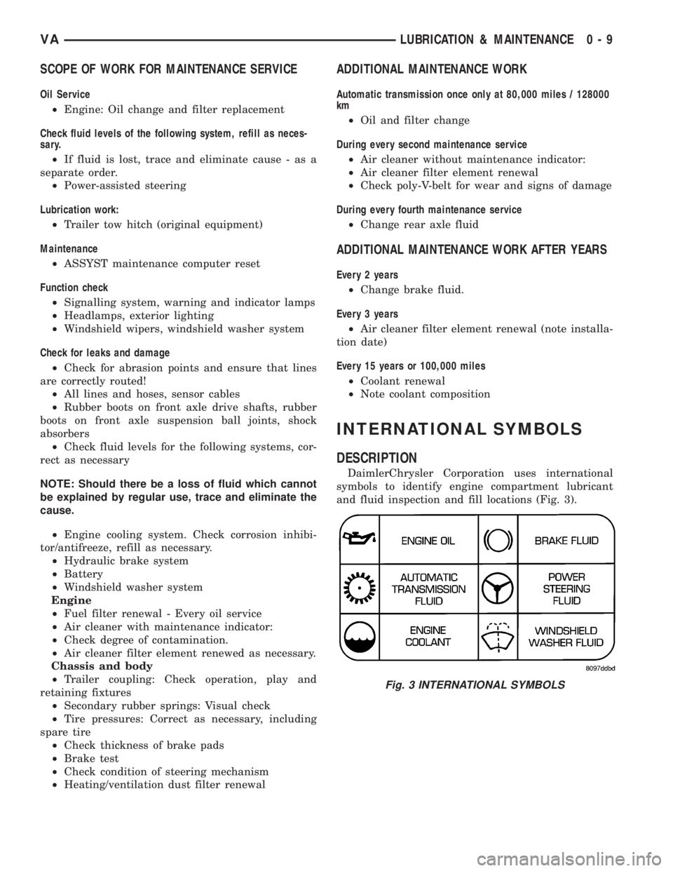
DaimlerChrysler Corporation uses international
symbols to identify engine compartment lubricant
and fluid inspection and fill locations (Fig. 3).
Fig. 3 INTERNATIONAL SYMBOLS
VALUBRICATION & MAINTENANCE 0 - 9
Page 844 of 2305
FAN DRIVE VISCOUS CLUTCH
REMOVAL
(1) For fan drive viscous clutch removal refer to
(Refer to 7 - COOLING/ENGINE/RADIATOR FAN -
REMOVAL).
INSTALLATION
(1) For fan drive viscous clutch installation refer to
(Refer to 7 - COOLING/ENGINE/RADIATOR FAN -
INSTALLATION).
RADIATOR
REMOVAL
WARNING: RISK OF INJURY TO SKIN AND EYES
FROM SCALDING WITH HOT COOLANT. RISK OF
POISONING FROM SWALLOWING COOLANT. DO
NOT OPEN COOLING SYSTEM UNLESS COOLANT
TEMPERATURE IS BELOW 90ÉC (194ÉF). OPEN CAP
SLOWLY TO RELEASE PRESSURE. STORE COOL-
ANT IN SUITABLE AND APPROPRIATELY MARKED
CONTAINER. WEAR PROTECTIVE GLOVES,
CLOTHES AND EYE WEAR.
NOTE: Capture all residual fluid spillage and store
in suitably marked containers. Inspect condition of
all clamps and hoses, replace as necessary.
(1) Drain coolant from radiator only (Refer to 7 -
COOLING/ENGINE/COOLANT - STANDARD PRO-
CEDURE).
(2) Remove headlamps.
(3) Remove front cross member together with front
grille.
(4) Remove front bumper.
(5) Remove bolts holding air charge hose to sheet
metal and intercooler.
(6) Detach air intake pipe at the body (Fig. 9).
(7) Detach both coolant hoses at the coolant reser-
voir (Fig. 9).
VAENGINE 7 - 17
Page 856 of 2305
ELECTRONIC CONTROL MODULES
TABLE OF CONTENTS
page page
CENTRAL TIMER MODULE
DESCRIPTION..........................1
OPERATION............................1
DIAGNOSIS AND TESTING - CENTRAL TIMER
MODULE.............................2
REMOVAL.............................2
INSTALLATION..........................3
CONTROLLER ANTILOCK BRAKE
DESCRIPTION..........................3
REMOVAL.............................3INSTALLATION..........................3
ENGINE CONTROL MODULE
DESCRIPTION..........................3
REMOVAL.............................6
INSTALLATION..........................6
TRANSMISSION CONTROL MODULE
DESCRIPTION..........................6
OPERATION............................7
STANDARD PROCEDURE - TCM ADAPTATION . 10
CENTRAL TIMER MODULE
DESCRIPTION
The central timer module (CTM) is located beneath
the driver seat. The CTM uses information carried on
the programmable communications interface (PCI)
data bus network along with many hard wired inputs
to monitor many sensor and switch inputs. In
response to those inputs, the circuitry and program-
ming of the CTM allow it to supply the vehicle occu-
pants with audible and visual information, and to
control and integrate many functions and features of
the vehicle through both hard wired outputs and the
transmission of message outputs to other modules in
the vehicle over the PCI data bus.
The features that the CTM supports or controls
include the following:
²Central Locking- The CTM on vehicles
equipped with the optional Vehicle Theft Security
System (VTSS) includes a central locking/unlocking
feature.
²Enhanced Accident Response- The CTM pro-
vides an optional enhanced accident response fea-
ture. This is a programmable feature.
²Panic Mode- The CTM provides support for
the optional RKE system panic mode including horn,
headlamp, and park lamp flash features.
²Power Lock Control- The CTM provides the
optional power lock system features, including sup-
port for the automatic door lock and door lock inhibit
modes.
²Programmable Features- The CTM provides
support for certain programmable features.
²Remote Keyless Entry- The CTM provides
the optional Remote Keyless Entry (RKE) system fea-
tures, including support for the RKE Lock (with
optional horn and park lamps flash), Unlock (with
park lamps flash, driver-door-only unlock, andunlock-all-doors), Panic, and illuminated entry
modes, as well as the ability to be programmed to
recognize up to four RKE transmitters. The RKE
horn, driver-door-only unlock, and unlock-all-doors
features are programmable.
²Vehicle Theft Security System- The CTM
provides control of the optional Vehicle Theft Secu-
rity System (VTSS) features, including support for
the central locking/unlocking mode and control of the
Security indicator in the instrument cluster.
Hard wired circuitry connects the CTM to the elec-
trical system of the vehicle. Refer to the appropriate
wiring information.
Many of the features in the vehicle controlled or
supported by the CTM are programmable using the
DRBIIItscan tool. However, if any of the CTM hard-
ware components are damaged or faulty, the entire
CTM unit must be replaced. The hard wired inputs
or outputs of all CTM versions can be diagnosed
using conventional diagnostic tools and methods;
however, for diagnosis of the CTM or the PCI data
bus, the use of a DRBIIItscan tool is required. Refer
to the appropriate diagnostic information.
OPERATION
The central timer module (CTM) monitors many
hard wired switch and sensor inputs as well as those
resources it shares with other modules in the vehicle
through its communication over the programmable
communications interface (PCI) data bus network.
The internal programming and all of these inputs
allow the CTM to determine the tasks it needs to
perform and their priorities, as well as both the stan-
dard and optional features that it should provide.
The CTM then performs those tasks and provides
those features through both PCI data bus communi-
cation with other modules and hard wired outputs
through a number of driver circuits, relays, and
VAELECTRONIC CONTROL MODULES 8E - 1
Page 874 of 2305
(2) Disconnect and isolate the battery negative
cable. Connect the battery charger leads. Some bat-
tery chargers are equipped with polarity-sensing cir-
cuitry. This circuitry protects the battery charger and
the battery from being damaged if they are improp-
erly connected. If the battery state-of-charge is too
low for the polarity-sensing circuitry to detect, the
battery charger will not operate. This makes it
appear that the battery will not accept charging cur-
rent. See the instructions provided by the manufac-
turer of the battery charger for details on how to
bypass the polarity-sensing circuitry.
(3) Battery chargers vary in the amount of voltage
and current they provide. The amount of time
required for a battery to accept measurable charging
current at various voltages is shown in the Charge
Rate Table. If the charging current is still not mea-
surable at the end of the charging time, the battery
is faulty and must be replaced. If the charging cur-
rent is measurable during the charging time, the bat-
tery may be good and the charging should be
completed in the normal manner.
CHARGE RATE TABLE
Voltage Hours
16.0 volts maximum up to 4 hours
14.0 to 15.9 volts up to 8 hours
13.9 volts or less up to 16 hours
CHARGING TIME REQUIRED
The time required to charge a battery will vary,
depending upon the following factors:
²Battery Capacity- A completely discharged
heavy-duty battery requires twice the charging time
of a small capacity battery.²Temperature- A longer time will be needed to
charge a battery at -18É C (0É F) than at 27É C (80É
F). When a fast battery charger is connected to a cold
battery, the current accepted by the battery will be
very low at first. As the battery warms, it will accept
a higher charging current rate (amperage).
²Charger Capacity- A battery charger that
supplies only five amperes will require a longer
charging time. A battery charger that supplies
twenty amperes or more will require a shorter charg-
ing time.
²State-Of-Charge- A completely discharged bat-
tery requires more charging time than a partially
discharged battery. Electrolyte is nearly pure water
in a completely discharged battery. At first, the
charging current (amperage) will be low. As the bat-
tery charges, the specific gravity of the electrolyte
will gradually rise.
The Battery Charging Time Table gives an indica-
tion of the time required to charge a typical battery
at room temperature based upon the battery state-of-
charge and the charger capacity.
BATTERY CHARGING TIME TABLE
Charging Amper-
age5 Amps10
Amps20 Amps
Open Circuit Volt-
ageHours Charging @ 21É C (70É
F)
12.25 to 12.49 6 hours 3 hours 1.5
hours
12.00 to 12.24 10 hours 5 hours 2.5
hours
10.00 to 11.99 14 hours 7 hours 3.5
hours
Below 10.00 18 hours 9 hours 4.5
hours
STANDARD PROCEDURE - OPEN - CIRCUIT
VOLTAGE TEST
A battery open-circuit voltage (no load) test will
show the approximate state-of-charge of a battery.
This test can be used in place of the hydrometer test
when a hydrometer is not available, or for mainte-
nance-free batteries with non-removable cell caps.
Before proceeding with this test, completely charge
the battery (Refer to 8 - ELECTRICAL/BATTERY
SYSTEM/BATTERY - STANDARD PROCEDURE).
(1) Before measuring the open-circuit voltage, the
surface charge must be removed from the battery.
Turn on the headlamps for fifteen seconds, then
allow up to five minutes for the battery voltage to
stabilize.
(2) Disconnect and isolate both battery cables, neg-
ative cable first.
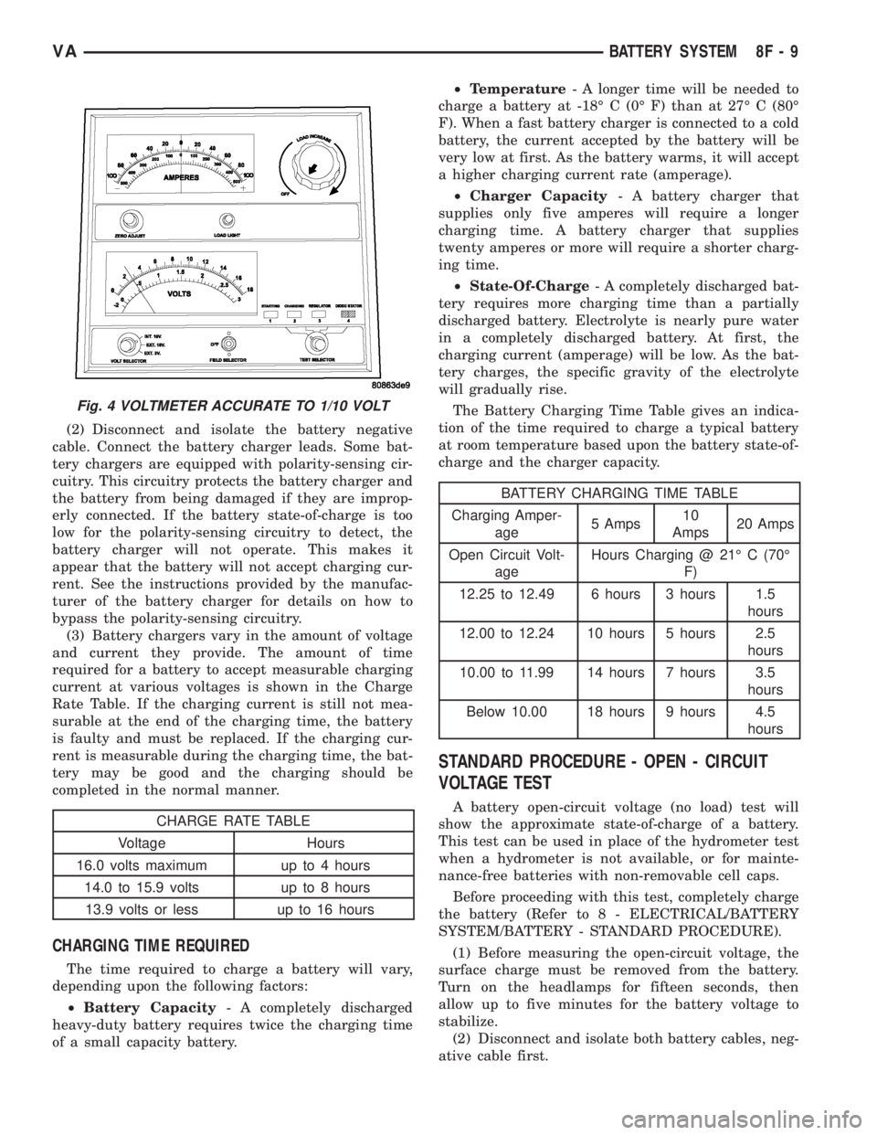
Fig. 4 VOLTMETER ACCURATE TO 1/10 VOLT
VABATTERY SYSTEM 8F - 9
Page 907 of 2305
DEFOGGER SWITCH CONNECTOR PIN
CALL-OUT
PIN FUNCTION
1 FUSED B+ (DRL RELAY)
3 IGNITION SWITCH OUTPUT (START-
RUN)
5 PANEL LAMPS DRIVER
7 DEFOGGER SWITCH OUTPUT
9 PANEL LAMPS DRIVER
10 GROUND
REMOVAL
WARNING: To avoid personal injury or death, on
vehicles equipped with airbags, disable the supple-
mental restraint system before attempting any
steering wheel, steering column, airbag, seat belt
tensioner, or instrument panel component diagno-
sis or service. Disconnect and isolate the battery
negative (ground) cable, then wait two minutes for
the system capacitor to discharge before perform-
ing further diagnosis or service. This is the only
sure way to disable the supplemental restraint sys-
tem. Failure to take the proper precautions could
result in accidental airbag deployment.
(1) Disconnect and isolate the negative battery
cable.
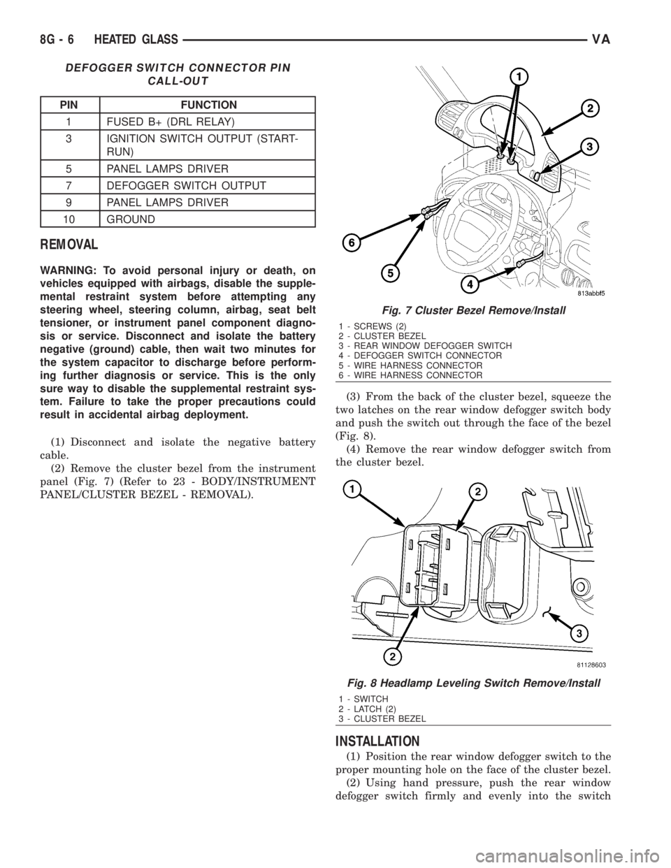
(2) Remove the cluster bezel from the instrument
panel (Fig. 7) (Refer to 23 - BODY/INSTRUMENT
PANEL/CLUSTER BEZEL - REMOVAL).(3) From the back of the cluster bezel, squeeze the
two latches on the rear window defogger switch body
and push the switch out through the face of the bezel
(Fig. 8).
(4) Remove the rear window defogger switch from
the cluster bezel.
INSTALLATION
(1) Position the rear window defogger switch to the
proper mounting hole on the face of the cluster bezel.
(2) Using hand pressure, push the rear window
defogger switch firmly and evenly into the switch
Fig. 7 Cluster Bezel Remove/Install
1 - SCREWS (2)
2 - CLUSTER BEZEL
3 - REAR WINDOW DEFOGGER SWITCH
4 - DEFOGGER SWITCH CONNECTOR
5 - WIRE HARNESS CONNECTOR
6 - WIRE HARNESS CONNECTOR
Fig. 8 Headlamp Leveling Switch Remove/Install
1 - SWITCH
2 - LATCH (2)
3 - CLUSTER BEZEL
8G - 6 HEATED GLASSVA