Air conditioner MERCEDES-BENZ SPRINTER 2006 Service Manual
[x] Cancel search | Manufacturer: MERCEDES-BENZ, Model Year: 2006, Model line: SPRINTER, Model: MERCEDES-BENZ SPRINTER 2006Pages: 2305, PDF Size: 48.12 MB
Page 830 of 2305
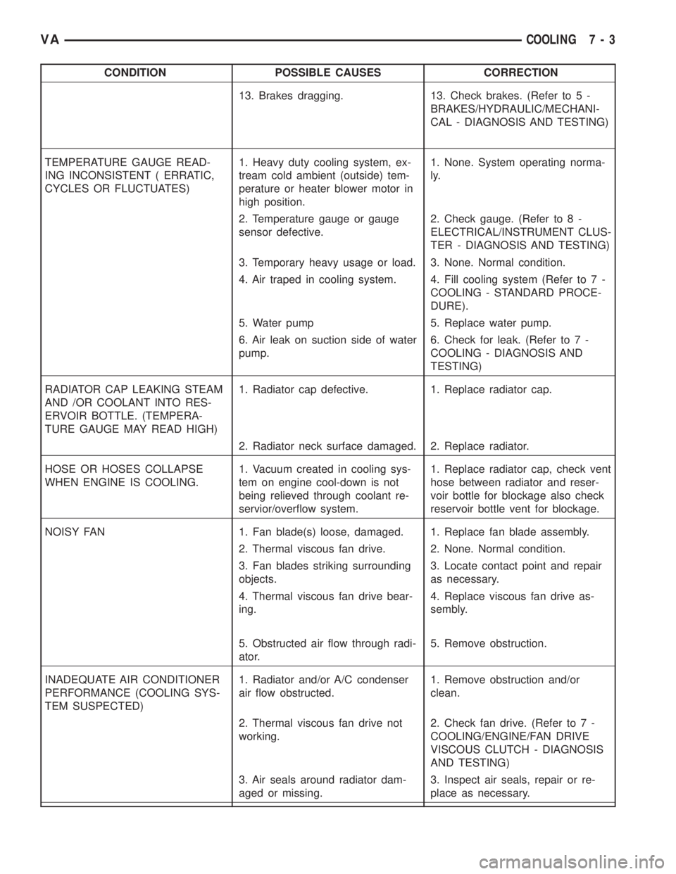
CONDITION POSSIBLE CAUSES CORRECTION
13. Brakes dragging. 13. Check brakes. (Refer to 5 -
BRAKES/HYDRAULIC/MECHANI-
CAL - DIAGNOSIS AND TESTING)
TEMPERATURE GAUGE READ-
ING INCONSISTENT ( ERRATIC,
CYCLES OR FLUCTUATES)1. Heavy duty cooling system, ex-
tream cold ambient (outside) tem-
perature or heater blower motor in
high position.1. None. System operating norma-
ly.
2. Temperature gauge or gauge
sensor defective.2. Check gauge. (Refer to 8 -
ELECTRICAL/INSTRUMENT CLUS-
TER - DIAGNOSIS AND TESTING)
3. Temporary heavy usage or load. 3. None. Normal condition.
4. Air traped in cooling system. 4. Fill cooling system (Refer to 7 -
COOLING - STANDARD PROCE-
DURE).
5. Water pump 5. Replace water pump.
6. Air leak on suction side of water
pump.6. Check for leak. (Refer to 7 -
COOLING - DIAGNOSIS AND
TESTING)
RADIATOR CAP LEAKING STEAM
AND /OR COOLANT INTO RES-
ERVOIR BOTTLE. (TEMPERA-
TURE GAUGE MAY READ HIGH)1. Radiator cap defective. 1. Replace radiator cap.
2. Radiator neck surface damaged. 2. Replace radiator.
HOSE OR HOSES COLLAPSE
WHEN ENGINE IS COOLING.1. Vacuum created in cooling sys-
tem on engine cool-down is not
being relieved through coolant re-
servior/overflow system.1. Replace radiator cap, check vent
hose between radiator and reser-
voir bottle for blockage also check
reservoir bottle vent for blockage.
NOISY FAN 1. Fan blade(s) loose, damaged. 1. Replace fan blade assembly.
2. Thermal viscous fan drive. 2. None. Normal condition.
3. Fan blades striking surrounding
objects.3. Locate contact point and repair
as necessary.
4. Thermal viscous fan drive bear-
ing.4. Replace viscous fan drive as-
sembly.
5. Obstructed air flow through radi-
ator.5. Remove obstruction.
INADEQUATE AIR CONDITIONER
PERFORMANCE (COOLING SYS-
TEM SUSPECTED)1. Radiator and/or A/C condenser
air flow obstructed.1. Remove obstruction and/or
clean.
2. Thermal viscous fan drive not
working.2. Check fan drive. (Refer to 7 -
COOLING/ENGINE/FAN DRIVE
VISCOUS CLUTCH - DIAGNOSIS
AND TESTING)
3. Air seals around radiator dam-
aged or missing.3. Inspect air seals, repair or re-
place as necessary.
VACOOLING 7 - 3
Page 859 of 2305
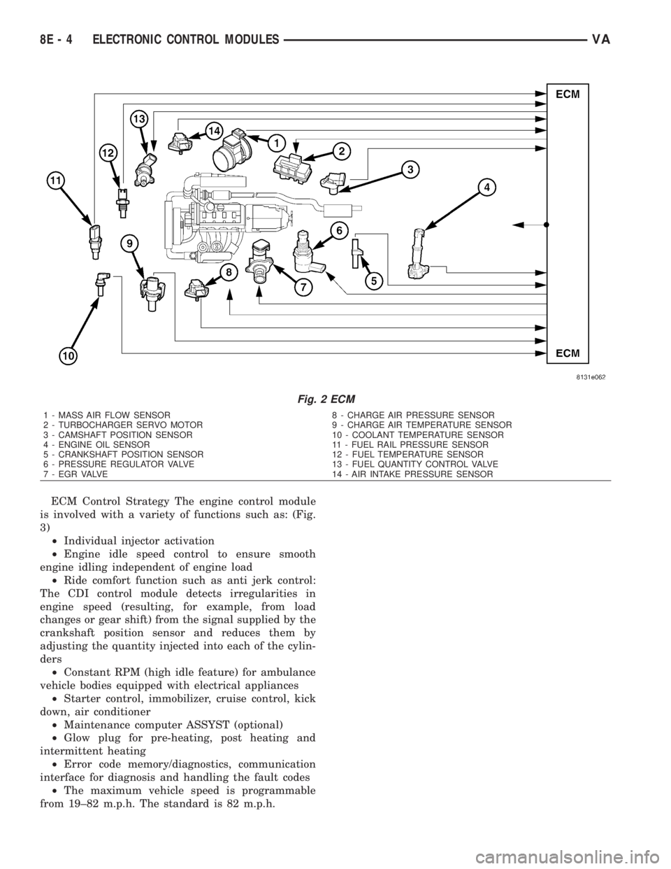
ECM Control Strategy The engine control module
is involved with a variety of functions such as: (Fig.
3)
²Individual injector activation
²Engine idle speed control to ensure smooth
engine idling independent of engine load
²Ride comfort function such as anti jerk control:
The CDI control module detects irregularities in
engine speed (resulting, for example, from load
changes or gear shift) from the signal supplied by the
crankshaft position sensor and reduces them by
adjusting the quantity injected into each of the cylin-
ders
²Constant RPM (high idle feature) for ambulance
vehicle bodies equipped with electrical appliances
²Starter control, immobilizer, cruise control, kick
down, air conditioner
²Maintenance computer ASSYST (optional)
²Glow plug for pre-heating, post heating and
intermittent heating
²Error code memory/diagnostics, communication
interface for diagnosis and handling the fault codes
²The maximum vehicle speed is programmable
from 19±82 m.p.h. The standard is 82 m.p.h.
Fig. 2 ECM
1 - MASS AIR FLOW SENSOR 8 - CHARGE AIR PRESSURE SENSOR
2 - TURBOCHARGER SERVO MOTOR 9 - CHARGE AIR TEMPERATURE SENSOR
3 - CAMSHAFT POSITION SENSOR 10 - COOLANT TEMPERATURE SENSOR
4 - ENGINE OIL SENSOR 11 - FUEL RAIL PRESSURE SENSOR
5 - CRANKSHAFT POSITION SENSOR 12 - FUEL TEMPERATURE SENSOR
6 - PRESSURE REGULATOR VALVE 13 - FUEL QUANTITY CONTROL VALVE
7 - EGR VALVE 14 - AIR INTAKE PRESSURE SENSOR
8E - 4 ELECTRONIC CONTROL MODULESVA
Page 998 of 2305
(1) Begin the cleanup by using a vacuum cleaner
to remove any residual powder from the vehicle inte-
rior. Clean from outside the vehicle and work your
way inside, so that you avoid kneeling or sitting on a
non-cleaned area.
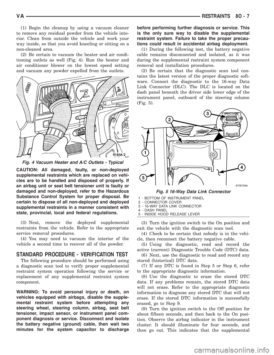
(2) Be certain to vacuum the heater and air condi-
tioning outlets as well (Fig. 4). Run the heater and
air conditioner blower on the lowest speed setting
and vacuum any powder expelled from the outlets.
CAUTION: All damaged, faulty, or non-deployed
supplemental restraints which are replaced on vehi-
cles are to be handled and disposed of properly. If
an airbag unit or seat belt tensioner unit is faulty or
damaged and non-deployed, refer to the Hazardous
Substance Control System for proper disposal. Be
certain to dispose of all non-deployed and deployed
supplemental restraints in a manner consistent with
state, provincial, local and federal regulations.
(3) Next, remove the deployed supplemental
restraints from the vehicle. Refer to the appropriate
service removal procedures.
(4) You may need to vacuum the interior of the
vehicle a second time to recover all of the powder.
STANDARD PROCEDURE - VERIFICATION TEST
The following procedure should be performed using
a diagnostic scan tool to verify proper supplemental
restraint system operation following the service or
replacement of any supplemental restraint system
component.
WARNING: To avoid personal injury or death, on
vehicles equipped with airbags, disable the supple-
mental restraint system before attempting any
steering wheel, steering column, airbag, seat belt
tensioner, impact sensor, or instrument panel com-
ponent diagnosis or service. Disconnect and isolate
the battery negative (ground) cable, then wait two
minutes for the system capacitor to dischargebefore performing further diagnosis or service. This
is the only sure way to disable the supplemental
restraint system. Failure to take the proper precau-
tions could result in accidental airbag deployment.
(1) During the following test, the battery negative
cable remains disconnected and isolated, as it was
during the supplemental restraint system component
removal and installation procedures.
(2) Be certain that the diagnostic scan tool con-
tains the latest version of the proper diagnostic soft-
ware. Connect the diagnostic to the 16-way Data
Link Connector (DLC). The DLC is located on the
dash panel beneath the driver side lower edge of the
instrument panel, outboard of the steering column
(Fig. 5).
(3) Turn the ignition switch to the On position and
exit the vehicle with the diagnostic scan tool.
(4) Check to be certain that nobody is in the vehi-
cle, then reconnect the battery negative cable.
(5) Using the diagnostic, read and record the
active (current) Diagnostic Trouble Code (DTC) data.
(6) Next, use the diagnostic to read and record any
stored (historical) DTC data.
(7) If any DTC is found in Step 5 or Step 6, refer
to the appropriate diagnostic information.
(8) Use the diagnostic to erase the stored DTC
data. If any problems remain, the stored DTC data
will not erase. Refer to the appropriate diagnostic
information to diagnose any stored DTC that will not
erase. If the stored DTC information is successfully
erased, go to Step 9.
(9) Turn the ignition switch to the Off position for
about fifteen seconds, and then back to the On posi-
tion. Observe the airbag indicator in the instrument
cluster. It should illuminate for four seconds, and
then go out. This indicates that the supplemental
Fig. 4 Vacuum Heater and A/C Outlets - Typical
Fig. 5 16-Way Data Link Connector
1 - BOTTOM OF INSTRUMENT PANEL
2 - CONNECTOR COVER
3 - 16-WAY DATA LINK CONNECTOR
4 - DASH PANEL
5 - INSIDE HOOD RELEASE LEVER
VARESTRAINTS 8O - 7
Page 1628 of 2305
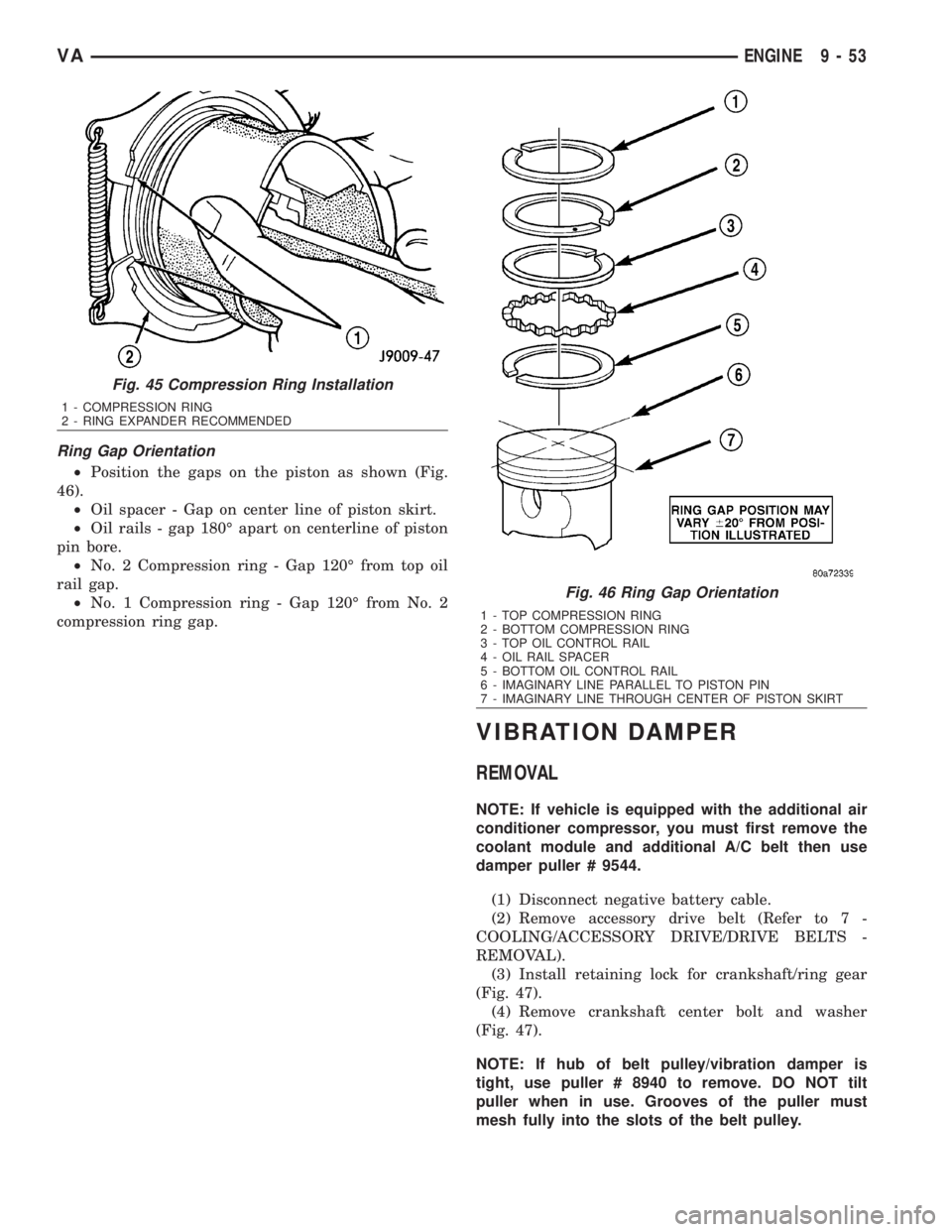
Ring Gap Orientation
²Position the gaps on the piston as shown (Fig.
46).
²Oil spacer - Gap on center line of piston skirt.
²Oil rails - gap 180É apart on centerline of piston
pin bore.
²No. 2 Compression ring - Gap 120É from top oil
rail gap.
²No. 1 Compression ring - Gap 120É from No. 2
compression ring gap.
VIBRATION DAMPER
REMOVAL
NOTE: If vehicle is equipped with the additional air
conditioner compressor, you must first remove the
coolant module and additional A/C belt then use
damper puller # 9544.
(1) Disconnect negative battery cable.
(2) Remove accessory drive belt (Refer to 7 -
COOLING/ACCESSORY DRIVE/DRIVE BELTS -
REMOVAL).
(3) Install retaining lock for crankshaft/ring gear
(Fig. 47).
(4) Remove crankshaft center bolt and washer
(Fig. 47).
NOTE: If hub of belt pulley/vibration damper is
tight, use puller # 8940 to remove. DO NOT tilt
puller when in use. Grooves of the puller must
mesh fully into the slots of the belt pulley.
Fig. 45 Compression Ring Installation
1 - COMPRESSION RING
2 - RING EXPANDER RECOMMENDED
Fig. 46 Ring Gap Orientation
1 - TOP COMPRESSION RING
2 - BOTTOM COMPRESSION RING
3 - TOP OIL CONTROL RAIL
4 - OIL RAIL SPACER
5 - BOTTOM OIL CONTROL RAIL
6 - IMAGINARY LINE PARALLEL TO PISTON PIN
7 - IMAGINARY LINE THROUGH CENTER OF PISTON SKIRT
VAENGINE 9 - 53
Page 1629 of 2305
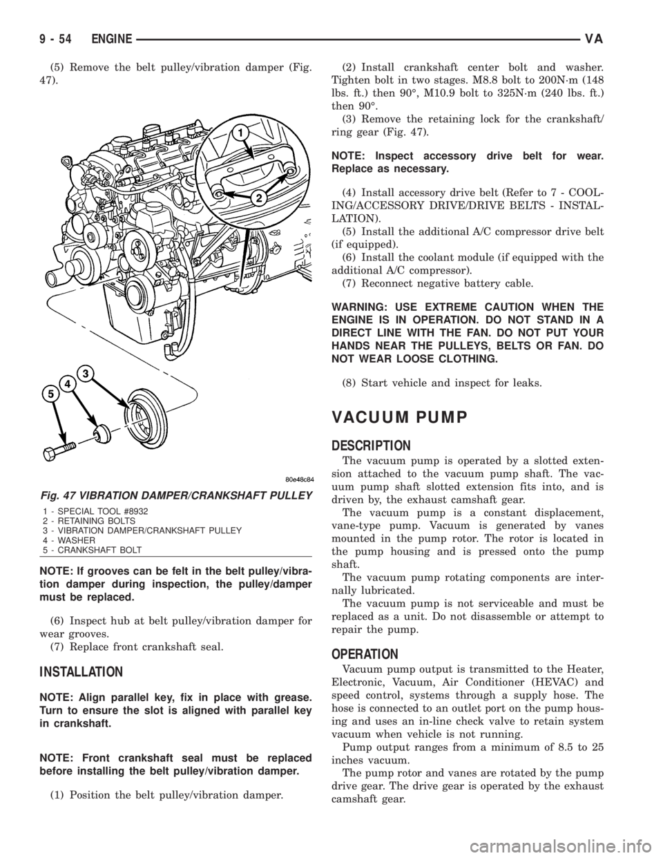
(5) Remove the belt pulley/vibration damper (Fig.
47).
NOTE: If grooves can be felt in the belt pulley/vibra-
tion damper during inspection, the pulley/damper
must be replaced.
(6) Inspect hub at belt pulley/vibration damper for
wear grooves.
(7) Replace front crankshaft seal.
INSTALLATION
NOTE: Align parallel key, fix in place with grease.
Turn to ensure the slot is aligned with parallel key
in crankshaft.
NOTE: Front crankshaft seal must be replaced
before installing the belt pulley/vibration damper.
(1) Position the belt pulley/vibration damper.(2) Install crankshaft center bolt and washer.
Tighten bolt in two stages. M8.8 bolt to 200N´m (148
lbs. ft.) then 90É, M10.9 bolt to 325N´m (240 lbs. ft.)
then 90É.
(3) Remove the retaining lock for the crankshaft/
ring gear (Fig. 47).
NOTE: Inspect accessory drive belt for wear.
Replace as necessary.
(4) Install accessory drive belt (Refer to 7 - COOL-
ING/ACCESSORY DRIVE/DRIVE BELTS - INSTAL-
LATION).
(5) Install the additional A/C compressor drive belt
(if equipped).
(6) Install the coolant module (if equipped with the
additional A/C compressor).
(7) Reconnect negative battery cable.
WARNING: USE EXTREME CAUTION WHEN THE
ENGINE IS IN OPERATION. DO NOT STAND IN A
DIRECT LINE WITH THE FAN. DO NOT PUT YOUR
HANDS NEAR THE PULLEYS, BELTS OR FAN. DO
NOT WEAR LOOSE CLOTHING.
(8) Start vehicle and inspect for leaks.
VACUUM PUMP
DESCRIPTION
The vacuum pump is operated by a slotted exten-
sion attached to the vacuum pump shaft. The vac-
uum pump shaft slotted extension fits into, and is
driven by, the exhaust camshaft gear.
The vacuum pump is a constant displacement,
vane-type pump. Vacuum is generated by vanes
mounted in the pump rotor. The rotor is located in
the pump housing and is pressed onto the pump
shaft.
The vacuum pump rotating components are inter-
nally lubricated.
The vacuum pump is not serviceable and must be
replaced as a unit. Do not disassemble or attempt to
repair the pump.
OPERATION
Vacuum pump output is transmitted to the Heater,
Electronic, Vacuum, Air Conditioner (HEVAC) and
speed control, systems through a supply hose. The
hose is connected to an outlet port on the pump hous-
ing and uses an in-line check valve to retain system
vacuum when vehicle is not running.
Pump output ranges from a minimum of 8.5 to 25
inches vacuum.
The pump rotor and vanes are rotated by the pump
drive gear. The drive gear is operated by the exhaust
camshaft gear.
Fig. 47 VIBRATION DAMPER/CRANKSHAFT PULLEY
1 - SPECIAL TOOL #8932
2 - RETAINING BOLTS
3 - VIBRATION DAMPER/CRANKSHAFT PULLEY
4 - WASHER
5 - CRANKSHAFT BOLT
9 - 54 ENGINEVA
Page 2099 of 2305
CAUTIONS
CAUTION: Never add R-12 to a refrigerant system
designed to use R-134a. Do not use R-12 equipment
or parts on a R-134a A/C system. These refrigerants
are not compatible and damage to the A/C system
will result.
CAUTION: Never use R-12 refrigerant oil in a A/C
system designed to use R-134a refrigerant oil.
These refrigerant oils are not compatible and dam-
age to the A/C system will result.
CAUTION: The use of A/C system sealers may
result in damage to A/C refrigerant recovery/evacu-
ation/recharging equipment and/or A/C system.
Many federal, state/provincial and local regulations
prohibit the recharge of A/C systems with known
leaks. DaimlerChrysler recommends the detection
of A/C system leaks through the use of approved
leak detectors and fluorescent leak detection dyes.
Vehicles found with A/C system sealers should be
treated as contaminated and replacement of the
entire A/C refrigerant system is recommended. A/C
systems found to be contaminated with A/C system
sealers, A/C stop-leak products or seal conditioners
voids the warranty for the A/C system.
CAUTION: Recover the refrigerant before opening
any fitting or connection. Open the fittings with
caution, even after the system has been dis-
charged. Never open or loosen a connection before
recovering the refrigerant.
CAUTION: If equipped, do not remove the second-
ary retention clip from any spring-lock coupler con-
nection while the refrigerant system is under
pressure. Recover the refrigerant before removing
the secondary retention clip. Open the fittings with
caution, even after the system has been dis-
charged. Never open or loosen a connection before
recovering the refrigerant.
CAUTION: The internal parts of the A/C system will
remain stable as long as moisture-free refrigerant
and refrigerant oil is used. Abnormal amounts of
dirt, moisture or air can upset the chemical stability.
This may cause operational troubles or even seri-
ous damage if present in more than very small
quantities. Before disconnecting a component,
clean the outside of the fittings thoroughly to pre-
vent contamination from entering the refrigerant
system. Keep service tools and the work area clean.
Do not open the refrigerant system or uncap areplacement component until you are ready to ser-
vice the system. Immediately after disconnecting a
component from the refrigerant system, seal the
open fittings with a cap or plug. This will prevent
contamination from entering the A/C system.
CAUTION: Refrigerant oil will absorb moisture from
the atmosphere if left uncapped. Do not open a
container of refrigerant oil until you are ready to
use it. Replace the cap on the oil container immedi-
ately after using. Store refrigerant oil only in a
clean, airtight, and moisture-free container.
CAUTION: Do not overcharge the refrigerant sys-
tem. Overcharging will cause excessive compressor
head pressure and can cause compressor noise
and A/C system failure.
DIAGNOSIS AND TESTING
REFRIGERANT SYSTEM LEAKS
WARNING: R-134a service equipment or vehicle A/C
system should not be pressure tested or leak tested
with compressed air. Mixture of air and R-134a can
be combustible at elevated pressures. These mix-
tures are potentially dangerous and may result in
fire or explosion causing property damage, per-
sonal injury or death.
Avoid breathing A/C refrigerant and lubricant vapor
or mist. Exposure may irritate eyes, nose and
throat. Use only approved service equipment meet-
ing SAE requirements to discharge R-134a system.
If accidental system discharge occurs, ventilate
work area before resuming service.
If the A/C system is not cooling properly, determine
if the refrigerant system is fully charged with
R-134a. This is accomplished by performing a Refrig-
erant System Charge Level test (Refer to 24 - HEAT-
ING & AIR CONDITIONING/PLUMBING -
DIAGNOSIS AND TESTING - REFRIGERANT SYS-
TEM CHARGE LEVEL) or by completely evacuating
and recharging the A/C system. If the A/C liquid line
pressure is found to be less than 345 kPa (50 psi)
while performing the Refrigerant System Charge
Level test, proceed to the System Empty procedure
below. If liquid line pressure is found to be greater
than 345 kPa (50 psi), proceed to the System Low
procedure. If the refrigerant system is empty or low
in refrigerant charge, a leak at any line fitting or
component seal is likely. A review of the fittings,
lines and components for oily residue is an indication
of the leak location. To detect a leak in the refriger-
ant system, perform one of the following procedures
as indicated by the symptoms.
24 - 62 PLUMBINGVA
Page 2101 of 2305
FRONTA/CSYSTEM
²LOW PRESSURE GAUGE HOSEÐThe low
pressure hose (Blue with Black stripe) attaches to
the suction line service port. This port is located on
the suction line near the dash panel.
²HIGH PRESSURE GAUGE HOSEÐThe high
pressure hose (Red with Black stripe) attaches to the
discharge line service port. This port is located on the
liquid line between the condenser and the reciver-
drier.
²RECOVERY/RECYCLING/EVACUATION/
CHARGING HOSEÐThe center manifold hose (Yel-
low, or White, with Black stripe) is used to recover,
evacuate, and charge the refrigerant system. When
the low or high pressure valves on the manifold
gauge set are opened, the refrigerant in the system
will escape through this hose.
REARA/CSYSTEM
²LOW PRESSURE GAUGE HOSEÐThe low
pressure hose (Blue with Black stripe) attaches to
the suction line service port. This port is located
within the rear A/C evaporator housing near the left
side of the evaporator, below the high-pressure ser-
vice port.
²HIGH PRESSURE GAUGE HOSEÐThe high
pressure hose (Red with Black stripe) attaches to the
liquid line service port. This port is located within
the rear A/C evaporator housing near the left side of
the evaporator, above the low-pressure service port.
²RECOVERY/RECYCLING/EVACUATION/
CHARGING HOSEÐThe center manifold hose (Yel-
low, or White, with Black stripe) is used to recover,
evacuate, and charge the refrigerant system. When
the low or high pressure valves on the manifold
gauge set are opened, the refrigerant in the system
will escape through this hose.
REFRIGERANT SYSTEM RECOVERY
WARNING: Refer to the applicable warnings and
cautions for this system before performing the fol-
lowing operation (Refer to 24 - HEATING & AIR
CONDITIONING/PLUMBING - WARNINGS) and (Refer
to 24 - HEATING & AIR CONDITIONING/PLUMBING -
CAUTIONS). Failure to follow the warnings and cau-
tions could result in possible personal injury or
death.
A R-134a refrigerant recovery/recycling/charging
station that meets SAE Standard J2210 must be
used to recover the refrigerant from an R-134a refrig-
erant system. Refer to the operating instructions sup-
plied by the equipment manufacturer for the proper
care and use of this equipment.
REFRIGERANT SYSTEM EVACUATE
WARNING: Refer to the applicable warnings and
cautions for this system before performing the fol-
lowing operation (Refer to 24 - HEATING & AIR
CONDITIONING/PLUMBING - WARNINGS) and (Refer
to 24 - HEATING & AIR CONDITIONING/PLUMBING -
CAUTIONS). Failure to follow the warnings and cau-
tions could result in possible personal injury or
death.
If the refrigerant system has been open to the
atmosphere, it must be evacuated before the system
can be charged. If moisture and air enters the system
and becomes mixed with the refrigerant, the com-
pressor head pressure will rise above acceptable
operating levels. This will reduce the performance of
the air conditioner and damage the compressor.
Evacuating the refrigerant system will remove the
air and boil the moisture out of the system at near
room temperature. To evacuate the refrigerant sys-
tem, use the following procedure:
(1) Connect a R-134a refrigerant recovery/recy-
cling/charging station that meets SAE Standard
J2210 and a manifold gauge set to the refrigerant
system of the vehicle.
(2) Open the low and high side valves and start
the charging station vacuum pump. When the suc-
tion gauge reads 88 kPa (26 in. Hg.) vacuum or
greater, close all of the valves and turn off the vac-
uum pump.
(a) If the refrigerant system fails to reach the
specified vacuum, the system has a leak that must
be corrected. (Refer to 24 - HEATING & AIR CON-
DITIONING/PLUMBING - DIAGNOSIS AND
TESTING - REFRIGERANT SYSTEM LEAKS)
(b) If the refrigerant system maintains the spec-
ified vacuum for five minutes, restart the vacuum
pump, open the suction and discharge valves and
evacuate the system for an additional ten minutes.
(3) Close all of the valves, and turn off the charg-
ing station vacuum pump.
(4) The refrigerant system is now ready to be
charged with R-134a refrigerant. (Refer to 24 -
HEATING & AIR CONDITIONING/PLUMBING -
STANDARD PROCEDURE - REFRIGERANT SYS-
TEM CHARGE)
REFRIGERANT SYSTEM CHARGE
WARNING: Refer to the applicable warnings and
cautions for this system before performing the fol-
lowing operation (Refer to 24 - HEATING & AIR
CONDITIONING/PLUMBING - WARNINGS) and (Refer
to 24 - HEATING & AIR CONDITIONING/PLUMBING -
CAUTIONS). Failure to follow the warnings and cau-
tions could result in possible personal injury or
death.
24 - 64 PLUMBINGVA
Page 2173 of 2305
5.0 REQUIRED TOOLS AND
EQUIPMENT
> DRBIIIt(diagnostic read-out box) - DRBIIIt
must use the latest release level.
> Jumper wires
> Test Light
> Ohmmeter
> Voltmeter
6.0 GLOSSARY OF TERMS
6.1 ACRONYMS
ABSAntilock Braking system
A/CAir conditioner
A/DAnalog to Digital conversion
APPAccelerator Pedal Position
CANController Area Network (Vehicle
Bus System)
CKTCircuit
DLCData Link Connector
DRBIIItDiagnostic Readout Box
DTCDiagnostic Trouble Code
ECMDiesel Engine Controller
EMCCElectronically Modulated Converter
Clutch
IODIgnition off-draw
ISSInput Speed Sensor (N2 and N3)
KK line communication bus
LEDLight Emitting Diode
MILMalfunction Indicator LampOSSOutput Speed Sensor (derived from
the ABS controller)
PEMCCPartial Electronically Modulated
Converter Clutch
PWMPulse width modulated
SKREEMSentry Key Remote Entry Module
SLAShift Lever Assembly
SWSwitch
TCCTorque Converter Clutch
TCMTransmission Control Module
TPThrottle Position
TRDTorque Reduction
TTSTransmission Temperature Sensor
1-2/4-5
solenoidcontrols the shift into and out of
2nd gear or 5th gear.
V2-3 so-
lenoidcontrols the shift into and out of 3rd
gear
V3-4 so-
lenoidcontrols the shift into and out of 4th
gear
VTCC
solenoidis pulse width modulated and con-
trols the TCC clutch
Shift
Pressure
Solenoidis a pulse width modulated solenoid
and controls the hydraulic pressure
to the shift elements.
Modula-
tion
pressure
solenoidis a pulse width modulated solenoid
and controls the hydraulic system
pressure
6.2 DEFINITIONS
Driving cycle counter) -The starts since first set
counter indicates the number of driving cycles since
the first occurrence of an error.
8
GENERAL INFORMATION