charging MERCEDES-BENZ SPRINTER 2006 Service Manual
[x] Cancel search | Manufacturer: MERCEDES-BENZ, Model Year: 2006, Model line: SPRINTER, Model: MERCEDES-BENZ SPRINTER 2006Pages: 2305, PDF Size: 48.12 MB
Page 109 of 2305
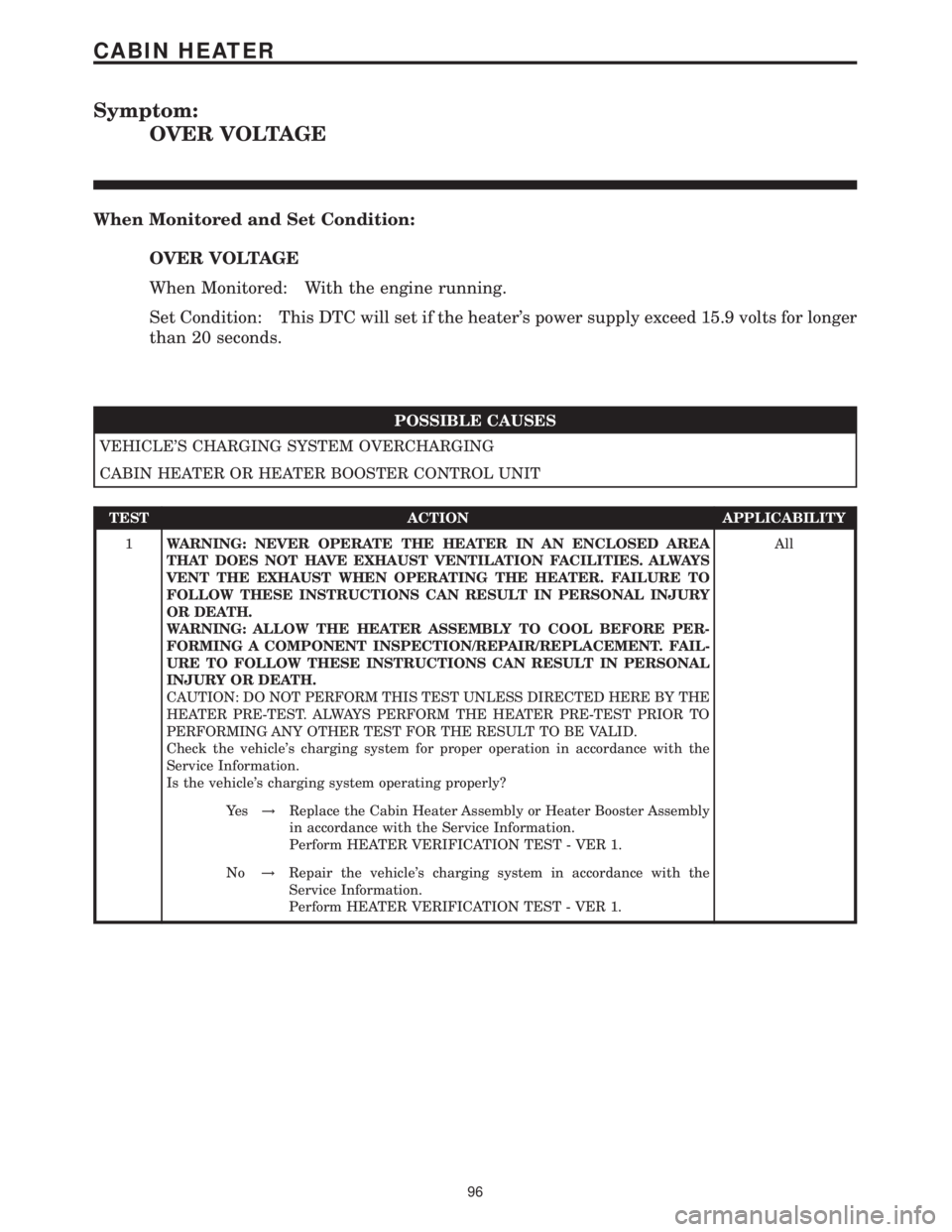
Symptom:
OVER VOLTAGE
When Monitored and Set Condition:
OVER VOLTAGE
When Monitored: With the engine running.
Set Condition: This DTC will set if the heater's power supply exceed 15.9 volts for longer
than 20 seconds.
POSSIBLE CAUSES
VEHICLE'S CHARGING SYSTEM OVERCHARGING
CABIN HEATER OR HEATER BOOSTER CONTROL UNIT
TEST ACTION APPLICABILITY
1WARNING: NEVER OPERATE THE HEATER IN AN ENCLOSED AREA
THAT DOES NOT HAVE EXHAUST VENTILATION FACILITIES. ALWAYS
VENT THE EXHAUST WHEN OPERATING THE HEATER. FAILURE TO
FOLLOW THESE INSTRUCTIONS CAN RESULT IN PERSONAL INJURY
OR DEATH.
WARNING: ALLOW THE HEATER ASSEMBLY TO COOL BEFORE PER-
FORMING A COMPONENT INSPECTION/REPAIR/REPLACEMENT. FAIL-
URE TO FOLLOW THESE INSTRUCTIONS CAN RESULT IN PERSONAL
INJURY OR DEATH.
CAUTION: DO NOT PERFORM THIS TEST UNLESS DIRECTED HERE BY THE
HEATER PRE-TEST. ALWAYS PERFORM THE HEATER PRE-TEST PRIOR TO
PERFORMING ANY OTHER TEST FOR THE RESULT TO BE VALID.
Check the vehicle's charging system for proper operation in accordance with the
Service Information.
Is the vehicle's charging system operating properly?All
Ye s!Replace the Cabin Heater Assembly or Heater Booster Assembly
in accordance with the Service Information.
Perform HEATER VERIFICATION TEST - VER 1.
No!Repair the vehicle's charging system in accordance with the
Service Information.
Perform HEATER VERIFICATION TEST - VER 1.
96
CABIN HEATER
Page 112 of 2305
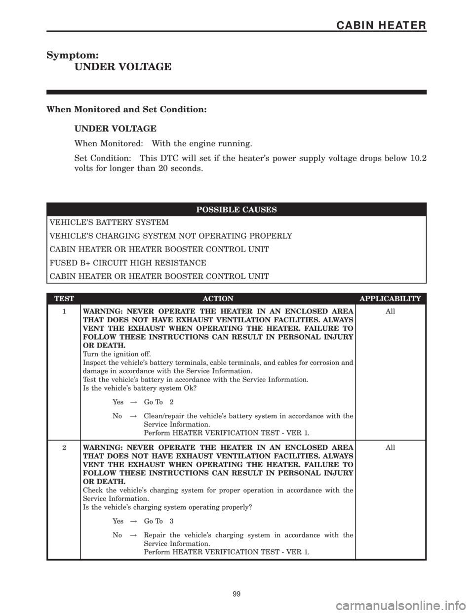
Symptom:
UNDER VOLTAGE
When Monitored and Set Condition:
UNDER VOLTAGE
When Monitored: With the engine running.
Set Condition: This DTC will set if the heater's power supply voltage drops below 10.2
volts for longer than 20 seconds.
POSSIBLE CAUSES
VEHICLE'S BATTERY SYSTEM
VEHICLE'S CHARGING SYSTEM NOT OPERATING PROPERLY
CABIN HEATER OR HEATER BOOSTER CONTROL UNIT
FUSED B+ CIRCUIT HIGH RESISTANCE
CABIN HEATER OR HEATER BOOSTER CONTROL UNIT
TEST ACTION APPLICABILITY
1WARNING: NEVER OPERATE THE HEATER IN AN ENCLOSED AREA
THAT DOES NOT HAVE EXHAUST VENTILATION FACILITIES. ALWAYS
VENT THE EXHAUST WHEN OPERATING THE HEATER. FAILURE TO
FOLLOW THESE INSTRUCTIONS CAN RESULT IN PERSONAL INJURY
OR DEATH.
Turn the ignition off.
Inspect the vehicle's battery terminals, cable terminals, and cables for corrosion and
damage in accordance with the Service Information.
Test the vehicle's battery in accordance with the Service Information.
Is the vehicle's battery system Ok?All
Ye s!Go To 2
No!Clean/repair the vehicle's battery system in accordance with the
Service Information.
Perform HEATER VERIFICATION TEST - VER 1.
2WARNING: NEVER OPERATE THE HEATER IN AN ENCLOSED AREA
THAT DOES NOT HAVE EXHAUST VENTILATION FACILITIES. ALWAYS
VENT THE EXHAUST WHEN OPERATING THE HEATER. FAILURE TO
FOLLOW THESE INSTRUCTIONS CAN RESULT IN PERSONAL INJURY
OR DEATH.
Check the vehicle's charging system for proper operation in accordance with the
Service Information.
Is the vehicle's charging system operating properly?All
Ye s!Go To 3
No!Repair the vehicle's charging system in accordance with the
Service Information.
Perform HEATER VERIFICATION TEST - VER 1.
99
CABIN HEATER
Page 200 of 2305
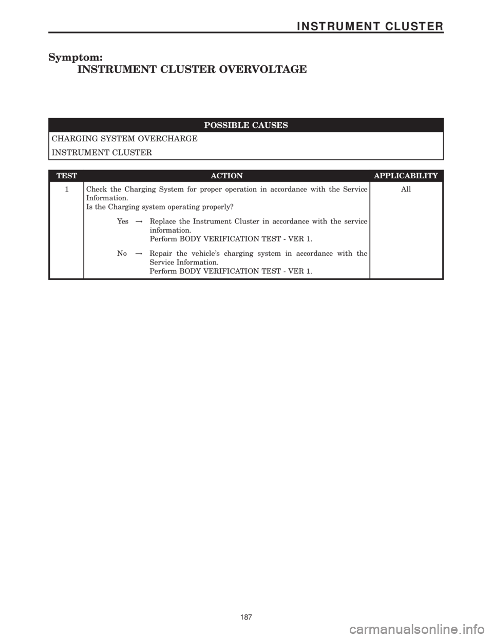
Symptom:
INSTRUMENT CLUSTER OVERVOLTAGE
POSSIBLE CAUSES
CHARGING SYSTEM OVERCHARGE
INSTRUMENT CLUSTER
TEST ACTION APPLICABILITY
1 Check the Charging System for proper operation in accordance with the Service
Information.
Is the Charging system operating properly?All
Ye s!Replace the Instrument Cluster in accordance with the service
information.
Perform BODY VERIFICATION TEST - VER 1.
No!Repair the vehicle's charging system in accordance with the
Service Information.
Perform BODY VERIFICATION TEST - VER 1.
187
INSTRUMENT CLUSTER
Page 381 of 2305
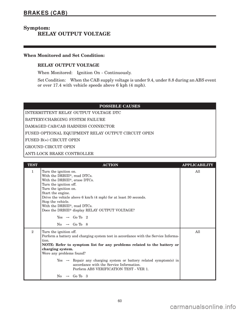
Symptom:
RELAY OUTPUT VOLTAGE
When Monitored and Set Condition:
RELAY OUTPUT VOLTAGE
When Monitored: Ignition On - Continuously.
Set Condition: When the CAB supply voltage is under 9.4, under 8.8 during an ABS event
or over 17.4 with vehicle speeds above 6 kph (4 mph).
POSSIBLE CAUSES
INTERMITTENT RELAY OUTPUT VOLTAGE DTC
BATTERY/CHARGING SYSTEM FAILURE
DAMAGED CAB/CAB HARNESS CONNECTOR
FUSED OPTIONAL EQUIPMENT RELAY OUTPUT CIRCUIT OPEN
FUSED B(+) CIRCUIT OPEN
GROUND CIRCUIT OPEN
ANTI-LOCK BRAKE CONTROLLER
TEST ACTION APPLICABILITY
1 Turn the ignition on.
With the DRBIIIt, read DTCs.
With the DRBIIIt, erase DTCs.
Turn the ignition off.
Turn the ignition on.
Start the engine.
Drive the vehicle above 6 km/h (4 mph) for at least 30 seconds.
Stop the vehicle.
With the DRBIIIt, read DTCs.
Does the DRBIIItdisplay RELAY OUTPUT VOLTAGE?All
Ye s!Go To 2
No!Go To 8
2 Turn the ignition off.
Perform a battery and charging system test in accordance with the Service Informa-
tion.
NOTE: Refer to symptom list for any problems related to the battery or
charging system.
Were any problems found?All
Ye s!Repair any charging system or battery related symptom(s) in
accordance with the Service Information.
Perform ABS VERIFICATION TEST - VER 1.
No!Go To 3
60
BRAKES (CAB)
Page 383 of 2305
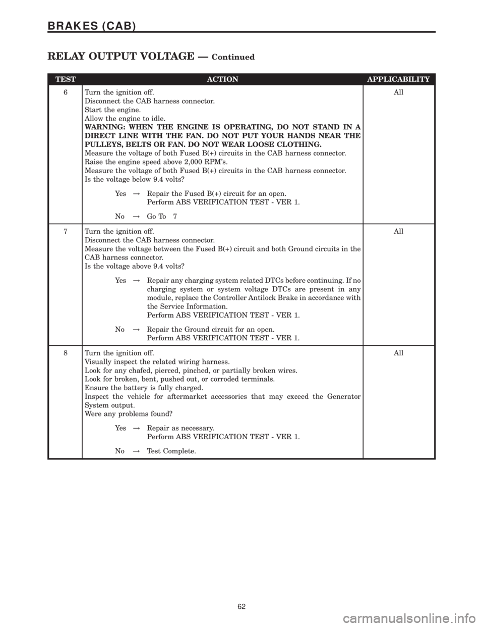
TEST ACTION APPLICABILITY
6 Turn the ignition off.
Disconnect the CAB harness connector.
Start the engine.
Allow the engine to idle.
WARNING: WHEN THE ENGINE IS OPERATING, DO NOT STAND IN A
DIRECT LINE WITH THE FAN. DO NOT PUT YOUR HANDS NEAR THE
PULLEYS, BELTS OR FAN. DO NOT WEAR LOOSE CLOTHING.
Measure the voltage of both Fused B(+) circuits in the CAB harness connector.
Raise the engine speed above 2,000 RPM's.
Measure the voltage of both Fused B(+) circuits in the CAB harness connector.
Is the voltage below 9.4 volts?All
Ye s!Repair the Fused B(+) circuit for an open.
Perform ABS VERIFICATION TEST - VER 1.
No!Go To 7
7 Turn the ignition off.
Disconnect the CAB harness connector.
Measure the voltage between the Fused B(+) circuit and both Ground circuits in the
CAB harness connector.
Is the voltage above 9.4 volts?All
Ye s!Repair any charging system related DTCs before continuing. If no
charging system or system voltage DTCs are present in any
module, replace the Controller Antilock Brake in accordance with
the Service Information.
Perform ABS VERIFICATION TEST - VER 1.
No!Repair the Ground circuit for an open.
Perform ABS VERIFICATION TEST - VER 1.
8 Turn the ignition off.
Visually inspect the related wiring harness.
Look for any chafed, pierced, pinched, or partially broken wires.
Look for broken, bent, pushed out, or corroded terminals.
Ensure the battery is fully charged.
Inspect the vehicle for aftermarket accessories that may exceed the Generator
System output.
Were any problems found?All
Ye s!Repair as necessary.
Perform ABS VERIFICATION TEST - VER 1.
No!Test Complete.
62
BRAKES (CAB)
RELAY OUTPUT VOLTAGE ÐContinued
Page 396 of 2305
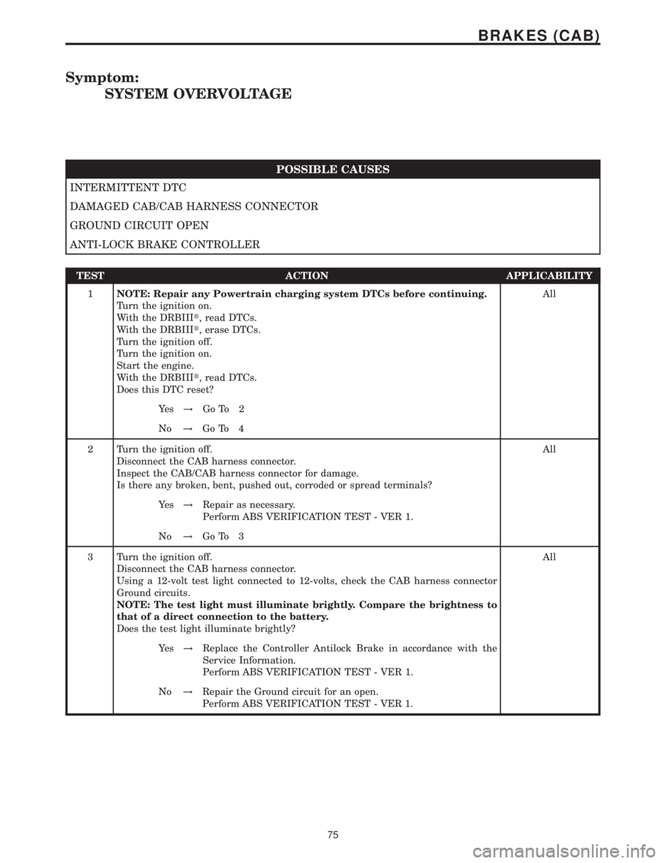
Symptom:
SYSTEM OVERVOLTAGE
POSSIBLE CAUSES
INTERMITTENT DTC
DAMAGED CAB/CAB HARNESS CONNECTOR
GROUND CIRCUIT OPEN
ANTI-LOCK BRAKE CONTROLLER
TEST ACTION APPLICABILITY
1NOTE: Repair any Powertrain charging system DTCs before continuing.
Turn the ignition on.
With the DRBIIIt, read DTCs.
With the DRBIIIt, erase DTCs.
Turn the ignition off.
Turn the ignition on.
Start the engine.
With the DRBIIIt, read DTCs.
Does this DTC reset?All
Ye s!Go To 2
No!Go To 4
2 Turn the ignition off.
Disconnect the CAB harness connector.
Inspect the CAB/CAB harness connector for damage.
Is there any broken, bent, pushed out, corroded or spread terminals?All
Ye s!Repair as necessary.
Perform ABS VERIFICATION TEST - VER 1.
No!Go To 3
3 Turn the ignition off.
Disconnect the CAB harness connector.
Using a 12-volt test light connected to 12-volts, check the CAB harness connector
Ground circuits.
NOTE: The test light must illuminate brightly. Compare the brightness to
that of a direct connection to the battery.
Does the test light illuminate brightly?All
Ye s!Replace the Controller Antilock Brake in accordance with the
Service Information.
Perform ABS VERIFICATION TEST - VER 1.
No!Repair the Ground circuit for an open.
Perform ABS VERIFICATION TEST - VER 1.
75
BRAKES (CAB)
Page 398 of 2305
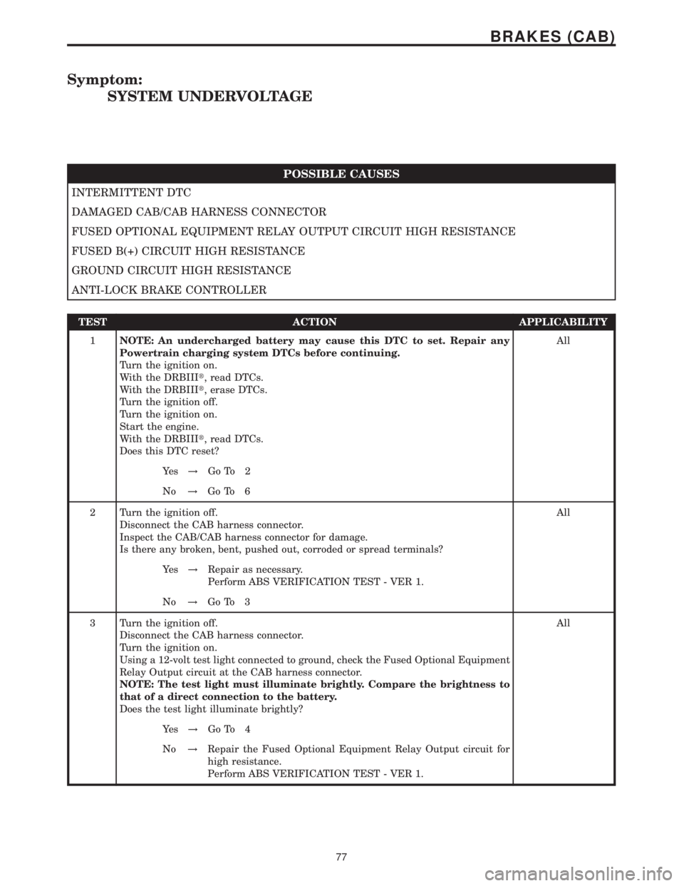
Symptom:
SYSTEM UNDERVOLTAGE
POSSIBLE CAUSES
INTERMITTENT DTC
DAMAGED CAB/CAB HARNESS CONNECTOR
FUSED OPTIONAL EQUIPMENT RELAY OUTPUT CIRCUIT HIGH RESISTANCE
FUSED B(+) CIRCUIT HIGH RESISTANCE
GROUND CIRCUIT HIGH RESISTANCE
ANTI-LOCK BRAKE CONTROLLER
TEST ACTION APPLICABILITY
1NOTE: An undercharged battery may cause this DTC to set. Repair any
Powertrain charging system DTCs before continuing.
Turn the ignition on.
With the DRBIIIt, read DTCs.
With the DRBIIIt, erase DTCs.
Turn the ignition off.
Turn the ignition on.
Start the engine.
With the DRBIIIt, read DTCs.
Does this DTC reset?All
Ye s!Go To 2
No!Go To 6
2 Turn the ignition off.
Disconnect the CAB harness connector.
Inspect the CAB/CAB harness connector for damage.
Is there any broken, bent, pushed out, corroded or spread terminals?All
Ye s!Repair as necessary.
Perform ABS VERIFICATION TEST - VER 1.
No!Go To 3
3 Turn the ignition off.
Disconnect the CAB harness connector.
Turn the ignition on.
Using a 12-volt test light connected to ground, check the Fused Optional Equipment
Relay Output circuit at the CAB harness connector.
NOTE: The test light must illuminate brightly. Compare the brightness to
that of a direct connection to the battery.
Does the test light illuminate brightly?All
Ye s!Go To 4
No!Repair the Fused Optional Equipment Relay Output circuit for
high resistance.
Perform ABS VERIFICATION TEST - VER 1.
77
BRAKES (CAB)
Page 523 of 2305
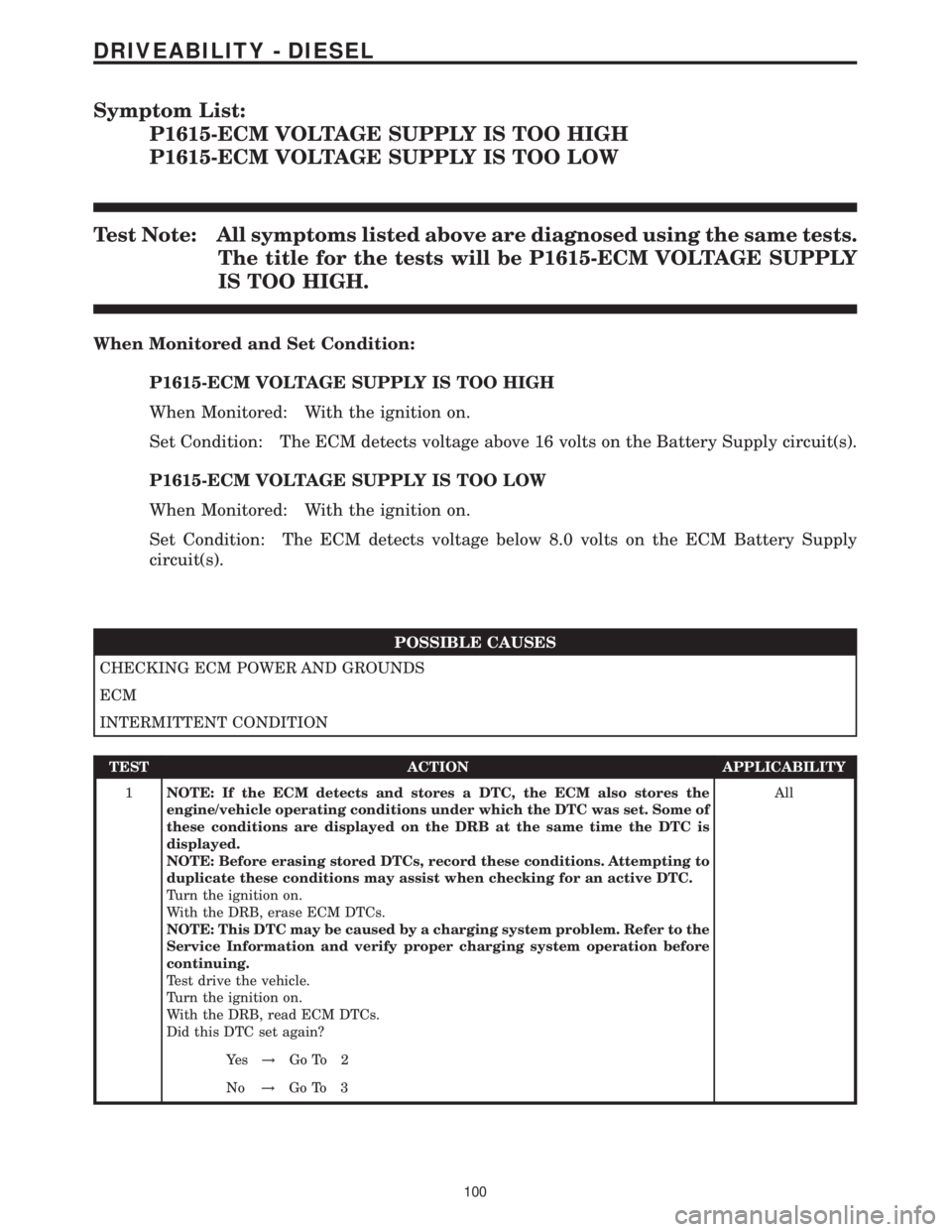
Symptom List:
P1615-ECM VOLTAGE SUPPLY IS TOO HIGH
P1615-ECM VOLTAGE SUPPLY IS TOO LOW
Test Note: All symptoms listed above are diagnosed using the same tests.
The title for the tests will be P1615-ECM VOLTAGE SUPPLY
IS TOO HIGH.
When Monitored and Set Condition:
P1615-ECM VOLTAGE SUPPLY IS TOO HIGH
When Monitored: With the ignition on.
Set Condition: The ECM detects voltage above 16 volts on the Battery Supply circuit(s).
P1615-ECM VOLTAGE SUPPLY IS TOO LOW
When Monitored: With the ignition on.
Set Condition: The ECM detects voltage below 8.0 volts on the ECM Battery Supply
circuit(s).
POSSIBLE CAUSES
CHECKING ECM POWER AND GROUNDS
ECM
INTERMITTENT CONDITION
TEST ACTION APPLICABILITY
1NOTE: If the ECM detects and stores a DTC, the ECM also stores the
engine/vehicle operating conditions under which the DTC was set. Some of
these conditions are displayed on the DRB at the same time the DTC is
displayed.
NOTE: Before erasing stored DTCs, record these conditions. Attempting to
duplicate these conditions may assist when checking for an active DTC.
Turn the ignition on.
With the DRB, erase ECM DTCs.
NOTE: This DTC may be caused by a charging system problem. Refer to the
Service Information and verify proper charging system operation before
continuing.
Test drive the vehicle.
Turn the ignition on.
With the DRB, read ECM DTCs.
Did this DTC set again?All
Ye s!Go To 2
No!Go To 3
100
DRIVEABILITY - DIESEL
Page 708 of 2305
FASTENER IDENTIFICATION
DESCRIPTION
The SAE bolt strength grades range from grade 2
to grade 8. The higher the grade number, the greater
the bolt strength. Identification is determined by the
line marks on the top of each bolt head. The actual
bolt strength grade corresponds to the number of line
marks plus 2. The most commonly used metric bolt
strength classes are 9.8 and 10.9. The metric
strength class identification number is imprinted on
the head of the bolt. The higher the class number,
the greater the bolt strength. Some metric nuts are
imprinted with a single-digit strength class on the
nut face. Refer to the Fastener Identification and
Fastener Strength Charts (Fig. 2) and (Fig. 3).
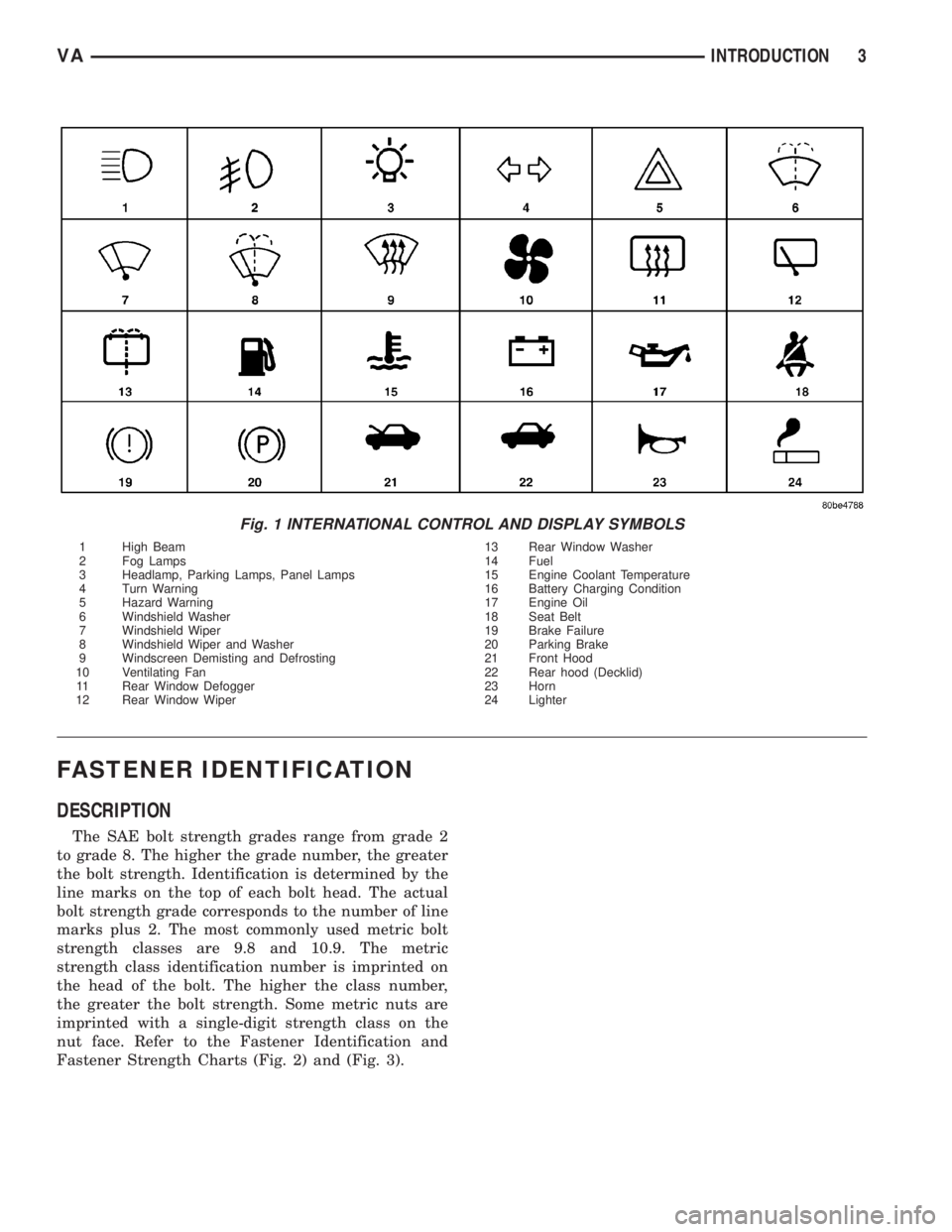
Fig. 1 INTERNATIONAL CONTROL AND DISPLAY SYMBOLS
1 High Beam 13 Rear Window Washer
2 Fog Lamps 14 Fuel
3 Headlamp, Parking Lamps, Panel Lamps 15 Engine Coolant Temperature
4 Turn Warning 16 Battery Charging Condition
5 Hazard Warning 17 Engine Oil
6 Windshield Washer 18 Seat Belt
7 Windshield Wiper 19 Brake Failure
8 Windshield Wiper and Washer 20 Parking Brake
9 Windscreen Demisting and Defrosting 21 Front Hood
10 Ventilating Fan 22 Rear hood (Decklid)
11 Rear Window Defogger 23 Horn
12 Rear Window Wiper 24 Lighter
VAINTRODUCTION 3
Page 721 of 2305
HOIST
A vehicle can be lifted with:
²A single-post, frame-contact hoist.
²A twin-post, chassis hoist.
²A ramp-type, drive-on hoist.
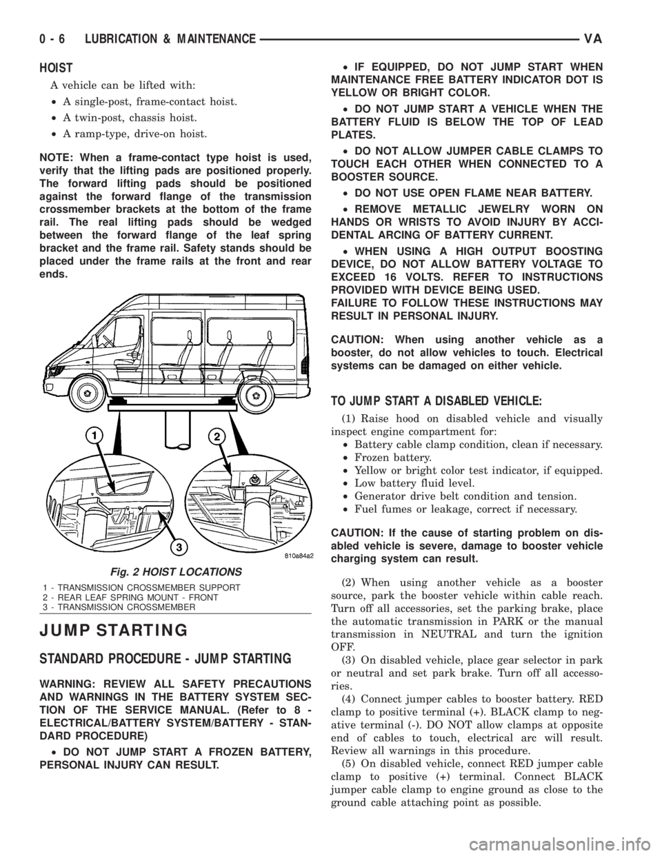
NOTE: When a frame-contact type hoist is used,
verify that the lifting pads are positioned properly.
The forward lifting pads should be positioned
against the forward flange of the transmission
crossmember brackets at the bottom of the frame
rail. The real lifting pads should be wedged
between the forward flange of the leaf spring
bracket and the frame rail. Safety stands should be
placed under the frame rails at the front and rear
ends.
JUMP STARTING
STANDARD PROCEDURE - JUMP STARTING
WARNING: REVIEW ALL SAFETY PRECAUTIONS
AND WARNINGS IN THE BATTERY SYSTEM SEC-
TION OF THE SERVICE MANUAL. (Refer to 8 -
ELECTRICAL/BATTERY SYSTEM/BATTERY - STAN-
DARD PROCEDURE)
²DO NOT JUMP START A FROZEN BATTERY,
PERSONAL INJURY CAN RESULT.²IF EQUIPPED, DO NOT JUMP START WHEN
MAINTENANCE FREE BATTERY INDICATOR DOT IS
YELLOW OR BRIGHT COLOR.
²DO NOT JUMP START A VEHICLE WHEN THE
BATTERY FLUID IS BELOW THE TOP OF LEAD
PLATES.
²DO NOT ALLOW JUMPER CABLE CLAMPS TO
TOUCH EACH OTHER WHEN CONNECTED TO A
BOOSTER SOURCE.
²DO NOT USE OPEN FLAME NEAR BATTERY.
²REMOVE METALLIC JEWELRY WORN ON
HANDS OR WRISTS TO AVOID INJURY BY ACCI-
DENTAL ARCING OF BATTERY CURRENT.
²WHEN USING A HIGH OUTPUT BOOSTING
DEVICE, DO NOT ALLOW BATTERY VOLTAGE TO
EXCEED 16 VOLTS. REFER TO INSTRUCTIONS
PROVIDED WITH DEVICE BEING USED.
FAILURE TO FOLLOW THESE INSTRUCTIONS MAY
RESULT IN PERSONAL INJURY.
CAUTION: When using another vehicle as a
booster, do not allow vehicles to touch. Electrical
systems can be damaged on either vehicle.
TO JUMP START A DISABLED VEHICLE:
(1) Raise hood on disabled vehicle and visually
inspect engine compartment for:
²Battery cable clamp condition, clean if necessary.
²Frozen battery.
²Yellow or bright color test indicator, if equipped.
²Low battery fluid level.
²Generator drive belt condition and tension.
²Fuel fumes or leakage, correct if necessary.
CAUTION: If the cause of starting problem on dis-
abled vehicle is severe, damage to booster vehicle
charging system can result.
(2) When using another vehicle as a booster
source, park the booster vehicle within cable reach.
Turn off all accessories, set the parking brake, place
the automatic transmission in PARK or the manual
transmission in NEUTRAL and turn the ignition
OFF.
(3) On disabled vehicle, place gear selector in park
or neutral and set park brake. Turn off all accesso-
ries.
(4) Connect jumper cables to booster battery. RED
clamp to positive terminal (+). BLACK clamp to neg-
ative terminal (-). DO NOT allow clamps at opposite
end of cables to touch, electrical arc will result.
Review all warnings in this procedure.
(5) On disabled vehicle, connect RED jumper cable
clamp to positive (+) terminal. Connect BLACK
jumper cable clamp to engine ground as close to the
ground cable attaching point as possible.
Fig. 2 HOIST LOCATIONS
1 - TRANSMISSION CROSSMEMBER SUPPORT
2 - REAR LEAF SPRING MOUNT - FRONT
3 - TRANSMISSION CROSSMEMBER
0 - 6 LUBRICATION & MAINTENANCEVA