reset MERCEDES-BENZ SPRINTER 2015 MY15 Operator’s Manual
[x] Cancel search | Manufacturer: MERCEDES-BENZ, Model Year: 2015, Model line: SPRINTER, Model: MERCEDES-BENZ SPRINTER 2015Pages: 334, PDF Size: 5.94 MB
Page 18 of 334
Releasing the parking lock man-
ually (automatic transmission)
........ 145
Remote control
Changing the operating duration
(auxiliary heating) .......................... 126
Replacing the battery (auxiliary
heating ) ........................................ 130
Switching on/off (auxiliary heat-
ing) ................................................ 126
Synchronizing (auxiliary heating) ... 126
Replacing bulbs
Important safety notes .................... 99
Replacing the battery (auxiliary
heating remote control) .................... 130
Restraint system
Introduction ..................................... 42
Warning lamp (function) .......... 42, 222
Reverse warning feature .................. 140
Roof carrier
Maximum payloa d.......................... 328
Notes ............................................. 245
Roof load (roof carrier) ..................... 328S
Safety Child restraint systems .................... 52
Children in the vehicle ..................... 51
Safety system
see Driving safety systems
Seat belts
Adjusting the height ......................... 45
Cleaning ......................................... 271
Correct usage .................................. 45
Display message ............................ 207
Fastening ......................................... 45
Important safety guidelines ............. 44
Introduction ..................................... 43
Releasing ......................................... 46
Warning lamp ................................. 227
Warning lamp (function) ................... 46
Seat heating ......................................... 87
Seats
Adjusting lumbar support ................ 83
Adjusting the co-driver's sea t.......... 83
Adjusting the head restraint ............ 86
Armrest ............................................ 87
Cleaning the cover ......................... 271 Correct driver's seat position ........... 82
Folding seat ..................................... 85
Important safety notes .................... 82
Rear bench seat ............................... 85
Seat heating .................................... 87
Setting the driver's seat ................... 83
Swivel seat ....................................... 84
Twin co-driver's seat ........................ 85
Securing loads
Important safety notes .................. 242
Selector lever
Cleaning ......................................... 270
Sensors (cleaning instructions) ....... 268
Service center
see Qualified specialist workshop
Service interval display
Calling up the service due date ...... 258
Exceeding a service due date ........ 258
Notes ............................................. 257
Service due date (automatic dis-
play) ............................................... 257
Service products
Brake fluid ..................................... 324
Coolant (engine) ............................ 325
Diesel ............................................ 318
Diesel Exhaust Fluid (DEF) ............. 320
Engine oil ....................................... 322
Fuel ................................................ 318
Important safety notes .................. 318
Power steering fluid ....................... 324
Refrigerant ..................................... 326
Transmission oil ............................. 324
Washer fluid ................................... 326
Setting the air distribution ............... 117
Setting the airflow ............................ 118
Setting the clock
Vehicles with steering wheel but-
tons ............................................... 191
Vehicles without steering wheel
buttons .......................................... 183
Settings
Resetting all (vehicles with steer-
ing wheel buttons) ......................... 188
Resetting submenus (vehicles
with steering wheel buttons) ......... 189
Short journeys (diesel particle fil-
ter) ...................................................... 153 16
Index
Page 19 of 334
Side windows
Cleaning ......................................... 267
Hinged side windows ....................... 78
Important safety information ........... 78
Opening/closing .............................. 78
Overview .......................................... 78
Problem (malfunction) ..................... 79
Resetting ......................................... 79
Sliding door
Child-proof locks .............................. 56
Cleaning ......................................... 269
Closing assist ................................... 73
Important safety notes .................... 72
Opening/closing .............................. 72
Opening/closing from the inside ..... 73
Opening/closing from the out-
side .................................................. 73
SmartKey
Changing the battery ....................... 69
Changing the locking system set-
tings ............................................... 194
Checking the battery ....................... 68
Display message ............................2 17
Door central locking/unlocking ....... 66
Important safety notes .................... 66
Loss ................................................. 70
Problem (malfunction) ..................... 70
SmartKey positions (ignition lock) .. 138
Snow chains ...................................... 287
Sockets .............................................. 236
Spare wheel
General notes ................................ 312
Important safety notes .................. 312
Removing/mounting ..................... .313
Special seat belt retractor .................. 52
Specialist workshop ............................ 25
Speed, controlling
see Cruise control
Speedometer
Digital (vehicles with steering
wheel buttons) ............................... 191
Digital (vehicles without steering
wheel buttons) ............................... 182
Selecting display unit (vehicles
with steering- wheel buttons) ....... .190
see Instrument cluster Sprinter Dealer
see Qualified specialist workshop
Standing lamps
Replacing bulbs ............................ .100
Replacing bulbs (rear) .................... 103
Standing lamps (Chassis Cab)
Replacing bulbs (rear) .................... 104
Start-off assist
Display message ............................ 205
Starting (engine) ................................ 139
Station
see Radio
Steering wheel
Adjusting ......................................... 88
Button overview ............................... 37
Cleaning ......................................... 270
Step
see Electrical step
Stickers
General safety notes ........................ 22
Stowage spaces
see Stowage spaces and stowagecompartments
Stowage spaces and stowage com-
partments
Eyeglasses compartment .............. .231
Glove box ....................................... 230
Important safety notes .................. 230
Paper holder .................................. 233
Stowage compartment above the
windshield ..................................... 232
Stowage compartment in the cen-
ter console ..................................... 232
Stowage compartment in the
dashboard ...................................... 231
Stowage space above the head-
liner ............................................... 232
Stowage space under the rear
bench seat ..................................... 233
Stowage space under the twin co-
driver's sea t................................... 232
Summer tires ..................................... 286
Switch unit
see Control panel
Switching off the alarm (ATA) ............ 61
Switching the heater booster func-
tion on/off ......................................... 130 Index
17
Page 22 of 334
Trailer
Brake force booster malfunction ... 219
Trailer coupling
see Towing a trailer
Trailer loads and drawbar nose-
weights .............................................. .177
Trailer towing
Blind Spot Assist ............................ 165
PARKTRONIC ................................. 170
Permissible trailer loads and
drawbar noseweights ..................... 177
Transmission
see Automatic transmission
Transmission oil ................................ 324
Transport
Loading guidelines ......................... 240
Vehicle .......................................... .280
Transport by rail ................................ 154
Transportation
Rail ................................................ 154
Transporting
Load distribution ............................ 242
Securing a load .............................. 242
Trim pieces (cleaning instruc-
tions) ................................................. .270
Trip computer (on-board com-
puter) ................................................. .195
Trip meter
see Trip odometer
Trip odometer
Display (vehicles with steering
wheel buttons) ............................... 187
Display (vehicles without steeringwheel buttons) ............................... 182
Resetting ....................................... 181
see Trip computer (on-board computer)
Turn signals
Replacing bulbs (front) ................... 102
Replacing bulbs (rear) .................... 103
Switching on/off .............................. 94
Turn signals (Chassis Cab)
Replacing bulbs (rear) .................... 104
Twin co-driver's seat
Folding table .................................. 234
Stowage compartment .................. 232
Two-way radios
Type approval/frequency .............. 316 TWR (Tongue Weight Rating) (defi-
nition)
................................................. 305 U
Unlocking From inside the vehicle (central
unlocking button) ............................ .71
USB port .............................................2 38 V
Vehicle Data acquisition ............................... 29
Display message ............................ 216
Electronics ..................................... 316
Equipment ....................................... 22
Individual settings (vehicles with
steering wheel buttons) ................. 188
Limited Warranty ............................ .22
Loading .......................................... 295
Locking (SmartKey) .......................... 66
Lowering ........................................ 310
Maintenance .................................... 28
Parking for a long period ................ 151
Pulling away ................................... 140
Raising ........................................... 307
Registration ............................... 25, 28
Reporting problems ......................... 28
Securing from rolling away ............ 149
Towing away .................................. 277
Transporting .................................. 280
Unlocking (SmartKey )...................... 66
Vehicle battery
see Battery (vehicle)
Vehicle bodies
Body/equipment mounting direc-
tives for trucks ................................. 26
Vehicle data ....................................... 327
Vehicle identification number .......... 316
Vehicle identification plate .............. 316
Vehicle tool kit .................................. 274
Vents
see Air vents
Voltage supply
Fuses ............................................. 280 20
Index
Page 36 of 334
Instrument cluster
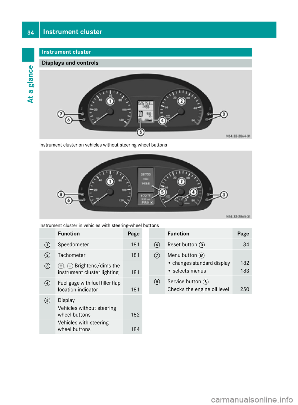
Displays and controls
Instrument cluster on vehicles without steering wheel buttons
Instrument cluster in vehicles with steering-wheel buttons
Function Page
0043
Speedometer 181
0044
Tachometer 181
0087
0074,
0075Brightens/dims the
instrument cluster lighting 181
0085
Fuel gage with fuel filler flap
location indicator 181
0083
Display
Vehicles without steering
wheel buttons
182
Vehicles with steering
wheel buttons 184 Function Page
0084
Reset button
0045 34
006B
Menu button
0079 • changes standard display 182
• selects menus 183
006C
Service button
0098 Checks the engine oil level 25034
Instrument clusterAt a glance
Page 81 of 334
Resetting the side windows
You must reset the side windows if there has
been a malfunction or an interruption in the
voltage supply.
X Turn the key to position 2in the ignition
lock.
X Pull the two power window switches and
hold for approximately 1 second after clos- ing the side window. Problems with the side windows
If you cannot completely open or close a side
window:
If there are no objects or leaves in the window guide that prevent the sliding sunroof from
closing, there has been a malfunction or the
on-board voltage has been interrupted.
X Reset the side window (Y page 79). Side windows
79Opening and closing Z
Page 127 of 334
Setting the switch-on time
X Use the same method to select a switch-on
time as described in the "Preselecting a
switch-on time" section.
On-board computer without steering
wheel buttons
X Press the 0045reset button on the instru-
ment cluster.
The hour display flashes.
X Use the 0074and 0075buttons on the instru-
ment cluster to set the hours.
X Press the 0045reset button
The minute display flashes.
X Use the 0074and 0075buttons to set the
minutes.
The switch-on time is set and selected.
On-board computer with steering wheel
buttons
X Press the 0063button on the steering
wheel.
The display shows the Hours
Hours menu.
X Use the 0081and0082 buttons on the
steering wheel to set the hours.
X Press the 0063button.
The display shows the Minutes
Minutes menu.
X Use the 0081and0082 buttons to set the
minutes.
X Press the 0080button.
The switch-on time is set and selected. Operation with the remote control
Important information You can switch the auxiliary heating on/off
and set the operating duration using the
remote control. You can use up to 4 remote
control units on the vehicle. These must be
synchronized for the receiver in your vehicle
(Y page 126). The remote control has a maximum range of
approximately 600 meters. This range is
reduced by:
R sources of interference
R solid objects between the remote control
and the vehicle
R the remote control being in an unfavorable
position in relation to the vehicle
R transmitting from an enclosed space
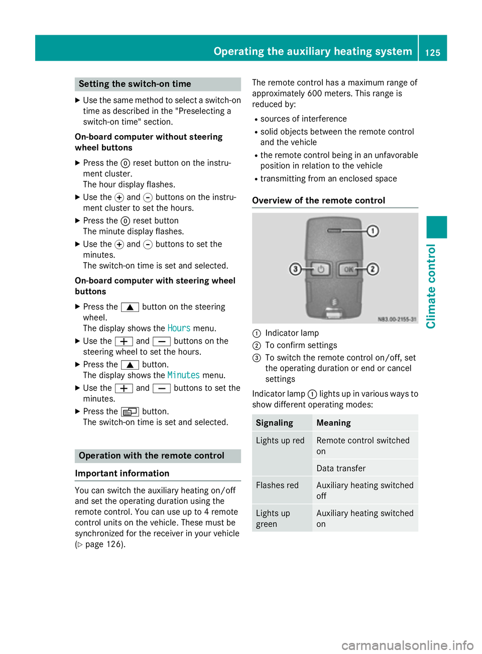
Overview of the remote control 0043
Indicator lamp
0044 To confirm settings
0087 To switch the remote control on/off, set
the operating duration or end or cancel
settings
Indicator lamp 0043lights up in various ways to
show different operating modes: Signaling Meaning
Lights up red Remote control switched
on
Data transfer
Flashes red Auxiliary heating switched
off
Lights up
green Auxiliary heating switched
onOperating the auxiliary heating system
125Climate control Z
Page 130 of 334
006C
Selects options in program column 0043or
menu bar 0044(backwards)
Reduces values
Activating the timer The timer switches to standby mode after
10 seconds. The display goes off.
X Press and hold the 00D0button until the
menu bar appears in the display and the
time is shown.
Setting the day, time and operating
duration You must reset the day, time, and default
value for the operating duration:
R during initial operation
R after a voltage supply interruption (e.g. if
the battery has been disconnected)
R after a malfunction.
You can find further information on malfunc-
tions in the "Problems with the auxiliary heat-
ing" section (Y page 132).
X Press the 00CFor00DB button until the
0045 symbol in menu bar 0044flashes.
X Press the 0070button.
In program column 0043, the day selected
flashes.
X Press the 00CFor00DB button to set the
desired day.
X Press the 0070button.
The day selected is stored. The hour setting
of the clock flashes.
X In the same way, set the hour and subse-
quently the minutes, then confirm by press- ing the 0070button.
The time is stored. Program column 0043dis-
appears and the operating duration
flashes.
i The operating duration set is the default
setting for immediate heating mode. You
can set the operating duration from 10 to
120 minutes or activate continuous opera-
tion. X
Using the 00CFor00DB button, set the
minute value or select the 00D5symbol for
continuous operation.
X Press the 0070button.
The operating duration is stored. The time
is shown.
Activating/deactivating immediate
heating mode X
To switch on: press the00CFor00DB but-
ton until the 0084symbol in the menu bar
flashes.
X Press the 0070button.
The operation duration flashes in the dis-
play.
i You can preset the default value that is
shown (Y page 128).
X Using the 00CFor00DB button, set the
minute value (10 – 120) or select the 00D5
symbol for continuous operation.
X Press the 0070button.
Immediate heating mode is activated. The
time and the 0084symbol appear.
X To switch off: press the00CFor00DB
button until the 0084symbol flashes in the
menu bar, and then press the 0070button.
Immediate heating mode is deactivated.
The 0084 symbol disappears.
The auxiliary heating operates for another
two minutes and then switches off auto-
matically.
i If you switch off the ignition while imme-
diate heating mode (operating duration
10– 120 minutes) is active, immediate
heating mode is also switched off. The aux- iliary heating operates for another
two minutes and then switches off auto-
matically.
If you have set continuous operation as the
operating duration and you switch off the
ignition, the auxiliary heating switches off
automatically after about 15 minute s.If, in
the remaining time, the ignition is switched
on again, continuous operation of the aux-
iliary heating continues. 128
Operating the auxiliary heating systemClimate control
Page 131 of 334
Setting the preselection time
G
WARNING
The auxiliary heating must not be operated if
there are highly flammable substances
nearby or in enclosed spaces without an
extraction system. Make sure that the auxili-
ary heating is not switched on automatically
by the timer in such places. If this possibility
exists, deactivate the respective programmed time.
You can set three preselection times using
the timer.
Observe that when setting the preselection
time, this does not correspond to the switch- on time but to the switch-off or departure
time. The auxiliary heating system starts up
automatically and runs for the operating dura-
tion set prior to departure.
Example: For a planned departure time of
7:00 a.m., you should also set the preselec-
tion time to 7:00 a.m. If the operating dura-
tion is preset to 40 minutes, for example, the
auxiliary heating starts up at 6:20 a.m.
If an identical time (time and day) is set in the preselection memory, only the last time set is
saved.
After a malfunction or if the battery has been disconnected, you must set the preselection
times again. You can find further information
on malfunctions in the "Problems with the
auxiliary heating" section (Y page 132).
X Press the 00CFor00DB button until the
0045 symbol in the menu bar flashes.
X Press the 0070button.
In the program column, the 0059preselec-
tion memory numbers appear. The selected preselection memory flashes.
X Press the 00CFor00DB button to select the
desired preselection memory.
X Press the 0070button.
The preselection memory is selected. The
days are shown. X
Set the day and time as described in the
"Setting the day, time and operating dura-
tion" section (Y page 128).
The preselection time is stored. The pro-
gram column disappears. In the display
panel, the on
on message and the 0084sym-
bol appear.
X Press the 0070button.
The operating duration flashes.
X Press the 00CFor00DB button to set the
minute value (10 – 120).
X Press the 0070button.
The operating duration for the preselection time is saved. The time and number of the
selected preselection memory are shown.
i The preselection memory that will be acti-
vated next is underlined. Additionally, the
day that is set appears.
Deactivating the preselection time X
Carry out the steps as described in the
"Setting the preselection time" section.
If the 0084 symbol in the status bar is shown:
X Press the 00CFor00DB button until the off off
message in the display panel is shown.
X Press the 0070button.
The preselection time is deactivated. The
time is shown.
Setting the heating level You can set the heating level to a range
between 10 and 30.
The heating level corresponds to a preselec-
tion temperature for the vehicle interior. This
is a guide value and may, depending on the
outside temperature, differ from the actual
vehicle interior temperature.
X Press the 00CFor00DB button until the
00D1 symbol in the menu bar flashes.
X Press the 0070button.
The heating level display flashes. Operating the auxiliary heating system
129Climate control Z
Page 139 of 334
Battery isolating switch
Important safety notes !
Make sure that the key is in position
0in
the ignition lock and wait at least 20 sec-
onds before disconnecting or connecting
the battery isolating switch. You could oth-
erwise damage electrical system compo-
nents.
You can use the battery isolating switch to
disconnect the power supply to all your vehi- cle's consumers. This will prevent uncontrol-
led battery discharge caused by off-load cur-
rent consumption.
If your vehicle is equipped with an auxiliary
battery in the engine compartment, you will
need to disconnect both batteries. Only then
is the electrical system fully disconnected
from the power supply.
i Only switch the vehicle to de-energized
using the battery main switch if:
R the vehicle is stationary for a lengthy
period
R it is absolutely necessary
After the power supply has been activated,
you will need to reset the side windows
(Y page 79).
Switching off the power supply !
When you clamp the connector under the
accelerator pedal, make sure that the con- nector does not become damaged or dirty.
It may otherwise not be possible to restore
the electrical connection when the parts
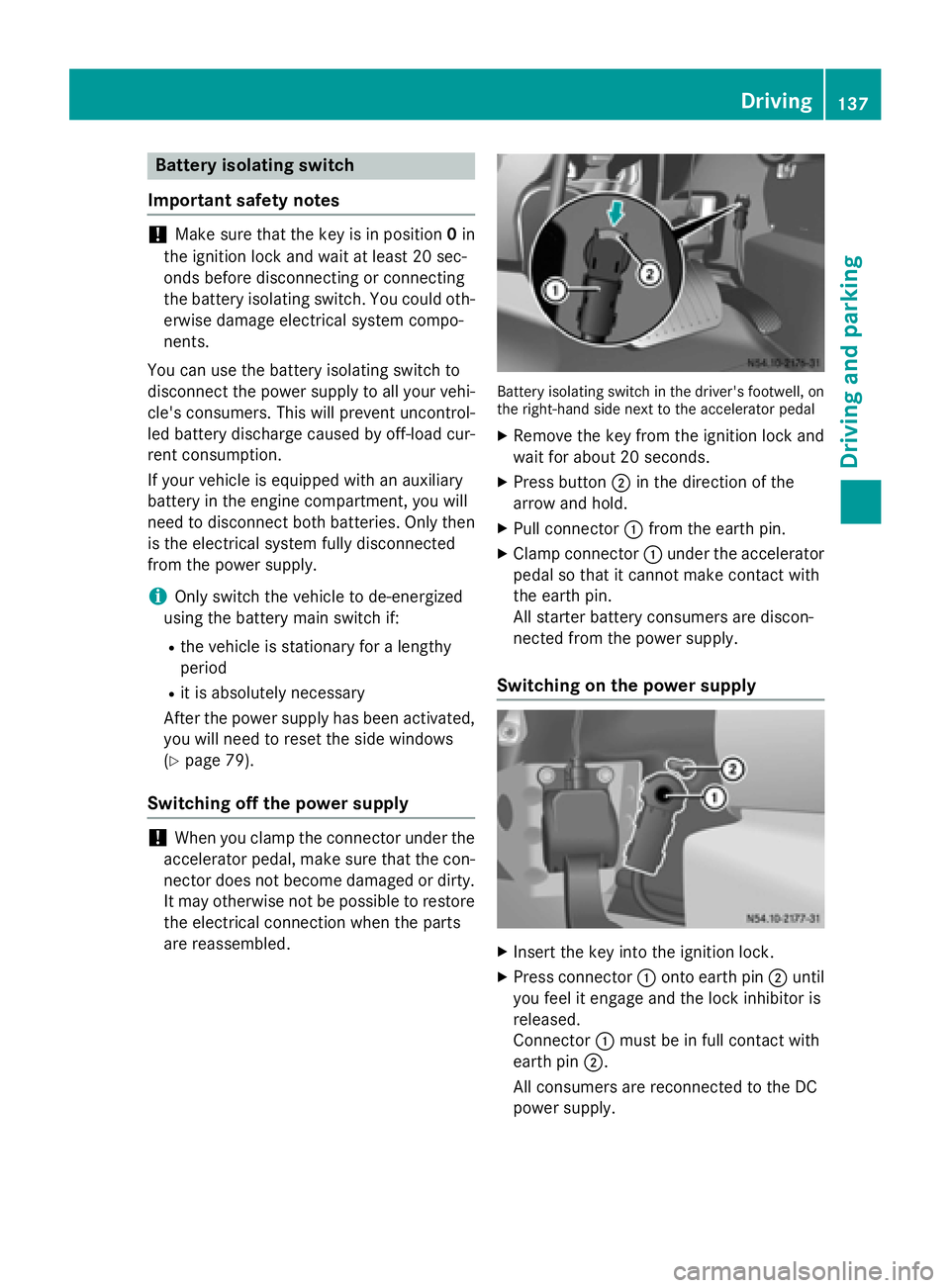
are reassembled. Battery isolating switch in the driver's footwell, on
the right-hand side next to the accelerator pedal
X Remove the key from the ignition lock and
wait for about 20 seconds.
X Press button 0044in the direction of the
arrow and hold.
X Pull connector 0043from the earth pin.
X Clamp connector 0043under the accelerator
pedal so that it cannot make contact with
the earth pin.
All starter battery consumers are discon-
nected from the power supply.
Switching on the power supply X
Insert the key into the ignition lock.
X Press connector 0043onto earth pin 0044until
you feel it engage and the lock inhibitor is
released.
Connector 0043must be in full contact with
earth pin 0044.
All consumers are reconnected to the DC
power supply. Driving
137Driving an d parking Z
Page 156 of 334
When you return from your journey, and as
close to the border as possible, you will need
to:
R remove the adhesive surfaces from your
halogen headlamps and clean the glass of
the headlamps if necessary
R have the Bi-Xenon headlamps reset to
asymmetrical low beam at a qualified spe-
cialist workshop Transport by rail
Transporting your vehicle by rail may be sub-
ject to certain restrictions or require special
measures to be taken in some countries due
to varying tunnel heights and loading stand-
ards.
You can obtain further information from any
authorized Sprinter dealer. Braking
Important safety notes G
WARNING
If you shift down on a slippery road surface in an attempt to increase the engine's braking
effect, the drive wheels could lose their grip.
There is an increased danger of skidding and
accidents.
Do not shift down for additional engine brak-
ing on a slippery road surface. G
WARNING
If you rest your foot on the brake pedal while
driving, the braking system can overheat. This increases the stopping distance and can even
cause the braking system to fail. There is a
risk of an accident.
Never use the brake pedal as a footrest. Never
depress the brake pedal and the accelerator
pedal at the same time.
! Depressing the brake pedal constantly
results in excessive and premature wear to
the brake pads. Downhill gradients !
Depressing the brake pedal constantly
results in excessive and premature wear to
the brake pads.
On long and steep downhill gradients, you
should change down to shift range 0048or0047
in good time. This should be observed in par- ticular when driving with a laden vehicle and
when towing a trailer.
i You must also change the shift range in
good time when cruise control is switched
on.
You thereby make use of the braking effect of the engine and do not have to brake as oftento maintain the speed. This relieves the load
on the service brake and prevents the brakes
from overheating and wearing too quickly.
Heavy and light loads G
WARNING
If you rest your foot on the brake pedal while
driving, the braking system can overheat. This increases the stopping distance and can even
cause the braking system to fail. There is a
risk of an accident.
Never use the brake pedal as a footrest. Never
depress the brake pedal and the accelerator
pedal at the same time.
! Depressing the brake pedal constantly
results in excessive and premature wear to
the brake pads.
If the brakes have been subjected to a heavy load, do not stop the vehicle immediately.
Drive on for a short while. The brakes are
cooled down more quickly in the airflow.
Wet road surfaces If you have been driving for a long time in
heavy rain without braking, there may be a
delayed response when you first apply the
brakes. This may also occur after driving
through a car wash or deep water. 154
Driving tipsDriving and parking