engine MERCEDES-BENZ SPRINTER 2017 MY17 Operator’s Manual
[x] Cancel search | Manufacturer: MERCEDES-BENZ, Model Year: 2017, Model line: SPRINTER, Model: MERCEDES-BENZ SPRINTER 2017Pages: 286, PDF Size: 4.36 MB
Page 200 of 286
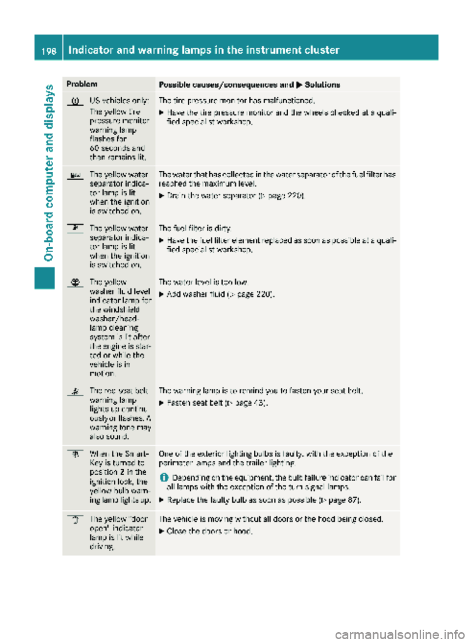
ProblemPossible causes/consequences andMSolutions
h
US vehicles only:
The yellow tire
pressure monitor
warning lamp
flashes for
60 seconds and
then remains lit.The tire pressure monitor has malfunctioned.
XHave the tire pressure monitor and the wheels checked at a quali-
fied specialist workshop.
:
The yellow water
separator indica-
tor lamp is lit
when the ignition
is switched on.The water that has collected in the water separator of the fuel filter has
reached the maximum level.
XDrain the water separator (Ypage 220).
m
The yellow water
separator indica-
tor lamp is lit
when the ignition
is switched on.The fuel filter is dirty.
XHave the fuel filter element replaced as soon as possible at a quali-
fied specialist workshop.
¦The yellow
washer fluid level
indicator lamp for
the windshield
washer/head-
lamp cleaning
system is lit after
the engine is star-
ted or while the
vehicle is in
motion.The water level is too low.
XAdd washer fluid (Ypage 220).
7The red seat belt
warning lamp
lights up continu-
ously or flashes. A
warning tone may
also sound.The warning lamp is to remind you to fasten your seat belt.
XFasten seat belt (Ypage 43).
bWhen the Smart-
Key is turned to
position 2in the
ignition lock, the
yellow bulb warn-
ing lamp lights up.One of the exterior lighting bulbs is faulty, with the exception of the
perimeter lamps and the trailer lighting.
iDepending on the equipment, the bulb failure indicator can fail for
all lamps with the exception of the turn signal lamps.
XReplace the faulty bulb as soon as possible (Ypage 87).
1 The yellow "door
open" indicator
lamp is lit while
driving.The vehicle is moving without all doors or the hood being closed.
XClose the doors or hood.
198Indicator and warning lamps in the instrument cluster
On-board computer and displays
Page 208 of 286
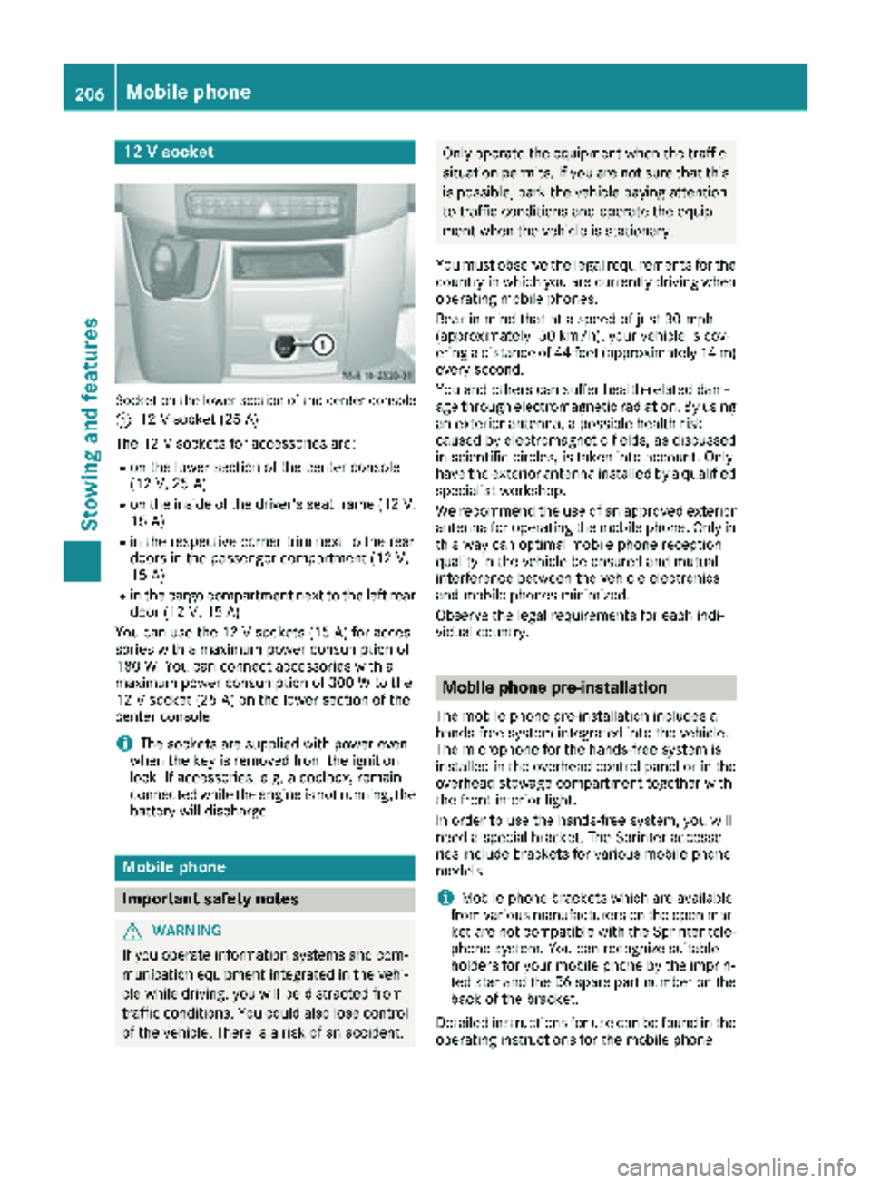
12 V socket
Socket on the lower section of the center console
:
12 V socket (25 A)
The 12 V sockets for accessories are:
Ron the lower section of the center console
(12 V, 25 A)
Ron the inside of the driver's seat frame (12V,
15 A)
Rin the respective corner trim next to the rear
doors in the passenger compartment (12 V,
15 A)
Rin the cargo compartment next to the left rear door (12 V,15 A)
You can use the 12 V sockets (15 A) for acces-
sories with a maximum power consumption of
180 W. You can connect accessories with a
maximum power consumption of 300 W to the
12 V socket (25 A) on the lower section of the
center console.
iThe sockets are supplied with power even
when the key is removed from the ignition
lock. If accessories, e.g. a coolbox, remain
connected while the engine is not running, the
battery will discharge.
Mobile phone
Important safety notes
GWARNING
If you operate information systems and com-
munication equipment integrated in the vehi-
cle while driving, you will be distracted from
traffic conditions. You could also lose control
of the vehicle. There is a risk of an accident.
Only operate the equipment when the traffic
situation permits. If you are not sure that this is possible, park the vehicle paying attention
to traffic conditions and operate the equip-
ment when the vehicle is stationary.
You must observe the legal requirements for the
country in which you are currently driving when
operating mobile phones.
Bear in mind that at a speed of just 30 mph
(approximately 50 km/h), your vehicle is cov-
ering a distance of 44 feet (approximately 14 m)
every second.
You and others can suffer health-related dam-
age through electromagnetic radiation. By using
an exterior antenna, a possible health risk
caused by electromagnetic fields, as discussed
in scientific circles, is taken into account. Only
have the exterior antenna installed by a qualified
specialist workshop.
We recommend the use of an approved exterior
antenna for operating the mobile phone. Only in
this way can optimal mobile phone reception
quality in the vehicle be ensured and mutual
interference between the vehicle electronics
and mobile phones minimized.
Observe the legal requirements for each indi-
vidual country.
Mobile phone pre-installation
The mobile phone pre-installation includes a
hands-free system integrated into the vehicle.
The microphone for the hands-free system is
installed in the overhead control panel or in the
overhead stowage compartment together with
the front interior light.
In order to use the hands-free system, you will
need a special bracket. The Sprinter accesso-
ries include brackets for various mobile phone
models.
iMobile phone brackets which are available
from various manufacturers on the open mar- ket are not compatible with the Sprinter tele-
phone system. You can recognize suitable
holders for your mobile phone by the imprin-
ted star and the B6 spare part number on the back of the bracket.
Detailed instructions for use can be found in the
operating instructions for the mobile phone
206Mobile phone
Stowing and features
Page 211 of 286
Load securing aids and tie downs may not be
used, for example, if:
Ridentification marks are missing or illegible
Rthere are yarn breakages, damage to bearingseams or other signs of tearing
Rthere are signs of shearing, deformation,
pinching or other damage
Rthere is damage to clamping or connecting
elements
Such load securing aids and tie downs are worn;
they should not be used and must be replaced. If
you use load securing aids or tie downs which
are worn, the load may not be sufficiently
secured and could cause damage to property.
After an accident, the following must be
checked at a specialist workshop:
RCargo compartment floor
RLoad surface
RCargo tie-down rings
RTie downs
Otherwise, the load may not be correctly
secured the next time anything is stowed.
Even if you follow all loading guidelines, the load
increases the risk of injury in the event of an
accident. Observe the tips in the "Securing lug-
gage/loads" (
Ypage 210) and "Load distribu-
tion" (Ypage 210) sections.
Before loading
!
The anti-slip mats cannot be used for secur-
ing goods and must be replaced when they
show signs of:
RPermanent deformation and crushing
RCrack formation
RCuts
XTire pressure: check the tire pressure and
correct if necessary (Ypage 246).
XCargo compartment floor: clean the cargo
compartment floor.
The cargo compartment floor must be free
from oil and dust, dry and swept clean to pre-
vent the load from slipping.
XPlace non-slip mats (anti-slip mats) on the
cargo compartment floor if necessary.
During loading
!
On passenger van versions with maximum
seating layout, the permissible rear axle load
would be exceeded if the full payload were to
be loaded in the cargo compartment.
XObserve the gross axle weight rating and per-
missible gross vehicle weight for your vehicle.
Take into account that your vehicle's curb
weight is increased if accessories or optional equipment are installed. The maximum pay-
load is thus reduced.
XObserve the notes on load distribution
(Ypage 210).
The overall center of gravity of the load should
always be as low as possible, centered and
between the axles near the rear axle.
XSecure the load (Ypage 210).
Observe the legal requirements of the country
in which you are currently driving.
Checks after loading
GWARNING
Combustion engines emit poisonous exhaust
gases, such as carbon monoxide. If the sliding door or rear door is open when the engine is
running, exhaust gases can enter the vehicle
interior, especially during the journey. There
is a risk of poisoning.
Always switch off the engine before opening
the sliding door or rear door. Never drive the
vehicle when the sliding door or rear door is
open.
XSecuring loads: check that the load is secure
before every journey and at regular intervals
during a long journey, and correct if neces-
sary.
XDoors: close the sliding doors and rear doors.
XTire pressure: adjust the tire pressures
according to the vehicle load (Ypage 246).
XDriving style: adapt your driving style
according to the vehicle load.
Loading guidelines209
Transporting loads
Z
Page 216 of 286
Useful information
This Operator's Manual describes all models as
well as standard and optional equipment of your
vehicle that were available at the time of going
to print. Country-specific variations are possi-
ble. Note that your vehicle may not be equipped
with all of the described functions. This also
applies to systems and functions relevant to
safety.
Read the information on qualified specialist
workshops (
Ypage 27).
Engine compartment
Hood
Important safety notes
GWARNING
If the hood is unlatched, it may open up when the vehicle is in motion and block your view.
There is a risk of an accident.
Never unlatch the hood while driving.
GWARNING
Opening the hood when the engine is over-
heated or when there is a fire in the engine
compartment could expose you to hot gases
or other service products. There is a risk of
injury.
Let an overheated engine cool down before
opening the hood. If there is a fire in the
engine compartment, keep the hood closed
and contact the fire department.
GWARNING
The engine compartment contains moving
components. Certain components, such as
the radiator fan, may continue to run or start
again suddenly when the ignition is off. There is a risk of injury.
If you need to do any work inside the engine
compartment:
Rswitch off the ignition
Rnever reach into the area where there is a
risk of danger from moving components,
such as the fan rotation area
Rremove jewelry and watches
Rkeep items of clothing and hair, for exam-
ple, away from moving parts
GWARNING
The fuel injection system operates with a high
voltage. If you touch the live components, you could receive an electric shock. There is a risk
of injury.
Never touch components of the fuel injection
system when the ignition is switched on.
The live components of the fuel injection system
are, for example, the injectors.
GWARNING
Certain components in the engine compart-
ment, such as the engine, radiator and parts
of the exhaust system, can become very hot.
Working in the engine compartment poses a
risk of injury.
Where possible, let the engine cool down and touch only the components described in the
following.
If you have to carry out work in the engine com-
partment, only touch the following components:
RHood
ROil dipstick
REngine oil filler neck cap
RWasher fluid reservoir cap
RCoolant expansion tank cap
Opening the hood
!Make sure that the windshield wipers are
not folded away from the windshield. You
could otherwise damage the windshield wip-
ers or the hood.
214Engine compartment
Maintenance and care
Page 217 of 286
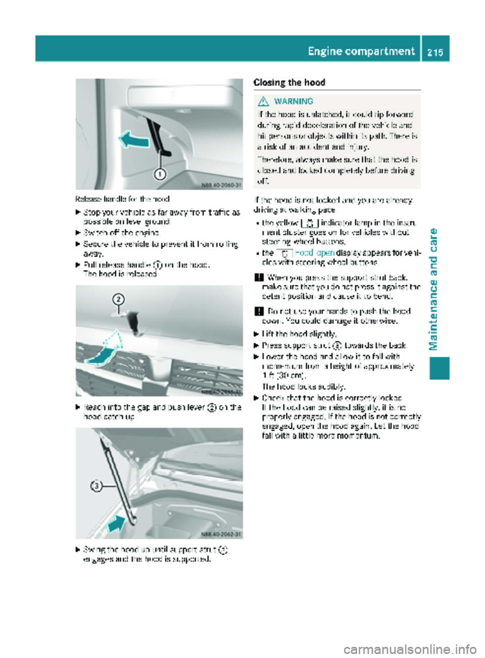
Releasehandle for th ehoo d
XStop your veh icleas far away fr omtraff icas
possible on level ground.
XSwitch off the engine.
XSecure the veh icleto prevent itfrom rolling
away.
XPull release handle :onthe hood.
The hoodis released.
XReach into the gap and push lever ;onthe
hoo d catch up.
XSwin g the hood up unt ilsupport strut =
engages and the hood issupported.
Closing the hood
GWARNIN G
If the hoodis unlatched, it could tip forward
during rapid decelerati on ofthe vehicle and
hit persons or objectswithin its path. There is
a risk ofan accident and injury.
Therefore, always make sure that the hood is
closed and locked co mpletely before driv ing
off.
If the hood is not locked and you are alrea dy
driving at walkingpace:
Rthe yellow 1indicat or lamp in theinstru-
ment cluster goes onfor vehicles without
steering-wheel butto ns.
Rthe 1 Hoodopendisp lay appears for vehi-
cles with steering-wheel butto ns.
!When you press the support strut back,
make sure that you do not press it against the
detent position and cause itto bend.
!Do no t use your hands to push thehood
down .You could damage it otherwise.
XLift the hood slightly.
XPress support strut =towards the back.
XLowe r the hood and allow itto fall with
mom entum fr oma height of approximat ely
1 ft (30 cm).
The hood locks audibly.
XChec k that the hood is correctly locke d.
If the hood can beraised slightly, it is not
properly engaged. If the hood is not correctly
engaged, openthehood again. Let the hood
fall with a little moremom entum.
Engine compartment215
Maintenance and care
Z
Page 218 of 286
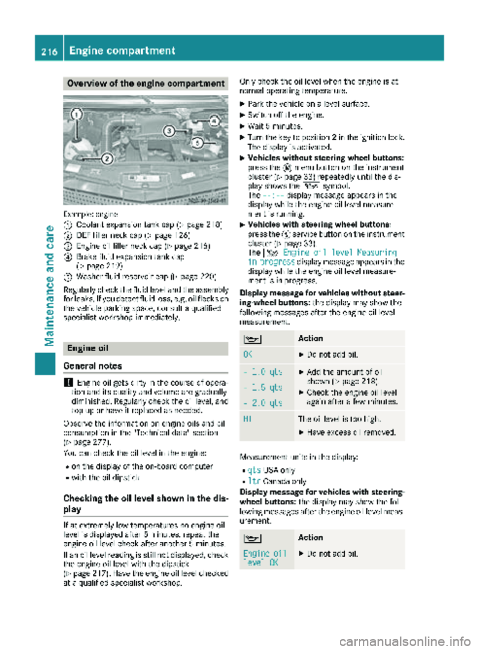
Overview of the engine compartment
Example: engine
:
Coolant expansion tank cap (Ypage 218)
;DEF filler neck cap (Ypage 126)
=Engine oil filler neck cap (Ypage 216)
?Brake fluid expansion tank cap
(Ypage 219)
AWasher fluid reservoir cap (Ypage 220)
Regularly check the fluid level and the assembly
for leaks. If you detect fluid loss, e.g. oil flecks on
the vehicle parking space, consult a qualified
specialist workshop immediately.
Engine oil
General notes
!Engine oil gets dirty in the course of opera-
tion and its quality and volume are gradually
diminished. Regularly check the oil level, and
top up or have it replaced as needed.
Observe the information on engine oils and oil
consumption in the "Technical data" section
(
Ypage 277).
You can check the oil level in the engine:
Ron the display of the on-board computer
Rwith the oil dipstick
Checking the oil level shown in the dis-
play
If at extremely low temperatures no engine oil
level is displayed after 5 minutes, repeat the
engine oil level check after another 5 minutes.
If an oil level reading is still not displayed, check
the engine oil level with the dipstick
(
Ypage 217). Have the engine oil level checked
at a qualified specialist workshop. Only check the oil level when the engine is at
normal operating temperature.
XPark the vehicle on a level surface.
XSwitch off the engine.
XWait 5 minutes.
XTurn the key to position
2in the ignition lock.
The display is activated.
XVehicles without steering wheel buttons:
press the 4menu button on the instrument
cluster (
Ypage 33) repeatedly until the dis-
play shows the 1symbol.
The --:--
display message appears in the
display while the engine oil level measure-
ment is running.
XVehicles with steering wheel buttons:
press the Ëservice button on the instrument
cluster (
Ypage 33).
The 4 Engine oil level Measuring
inprogressdisplay message appears in the
display while the engine oil level measure-
ment is in progress.
Display message for vehicles without steer-
ing-wheel buttons: the display may show the
following messages after the engine oil level
measurement.
1Action
OKXDo not add oil.
– 1.0 qtsXAdd the amount of oil
shown (Ypage 218).
XCheck the engine oil level
again after a few minutes.– 1.5 qts
– 2.0 qts
HIThe oil level is too high.
XHave excess oil removed.
Measurement units in the display:
RqtsUSA only
RltrCanada only
Display message for vehicles with steering- wheel buttons: the display may show the fol-
lowing messages after the engine oil level meas-
urement.
1Action
Engineoillevel OKXDo not add oil.
216Engine compartment
Maintenance and care
Page 219 of 286
EngineoilAdd1.0 quart
XAdd the amount of oil
shown (Ypage 218).
XCheck the engine oil level
again after a few minutes.
EngineoilAdd1.5quarts
EngineoilAdd2.0quarts
EngineoillevelReduceoillevel
The oil level is too high.
XHave excess oil removed.
Eng. oillev. Turnignitionon forlevel
XTurn the key to position2in
the ignition lock.
Observewait.period
XRepeat the engine oil
measurement after about
5 minutes if the engine is at
normal operating tempera-
ture.
XRepeat the engine oil
measurement after about
30 minutes if the engine is
not at normal operating
temperature.
Engineoillevel Notwhen eng.running
XSwitch off the engine when it is at normal operating
temperature and wait
approximately 5 minutes
before measuring the
engine oil level.
Measurement units in the display:
RqtsUSA only
RltrCanada only
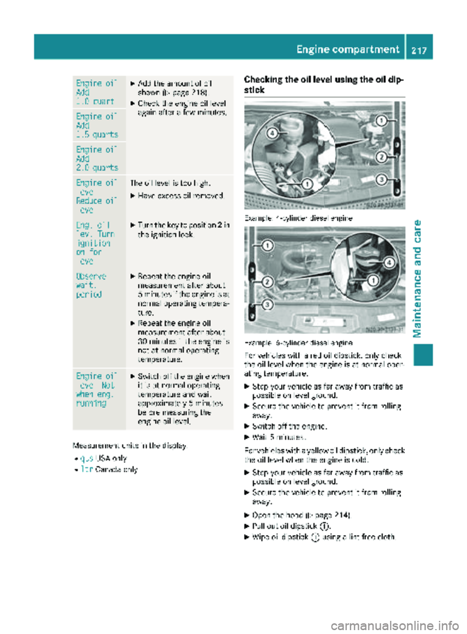
Checking the oil level using the oil dip-
stick
Example: 4-cylinder diesel engine
Example: 6-cylinder diesel engine
For vehicles with a red oil dipstick, only check
the oil level when the engine is at normal oper-
ating temperature:
XStop your vehicle as far away from traffic as
possible on level ground.
XSecure the vehicle to prevent it from rolling
away.
XSwitch off the engine.
XWait 5 minutes.
For vehicles with a yellow oil dipstick, only check
the oil level when the engine is cold.
XStop your vehicle as far away from traffic as
possible on level ground.
XSecure the vehicle to prevent it from rolling
away.
XOpen the hood (Ypage 214).
XPull out oil dipstick :.
XWipe oil dipstick:using a lint-free cloth.
Engine compartment217
Maintenance and care
Z
Page 220 of 286
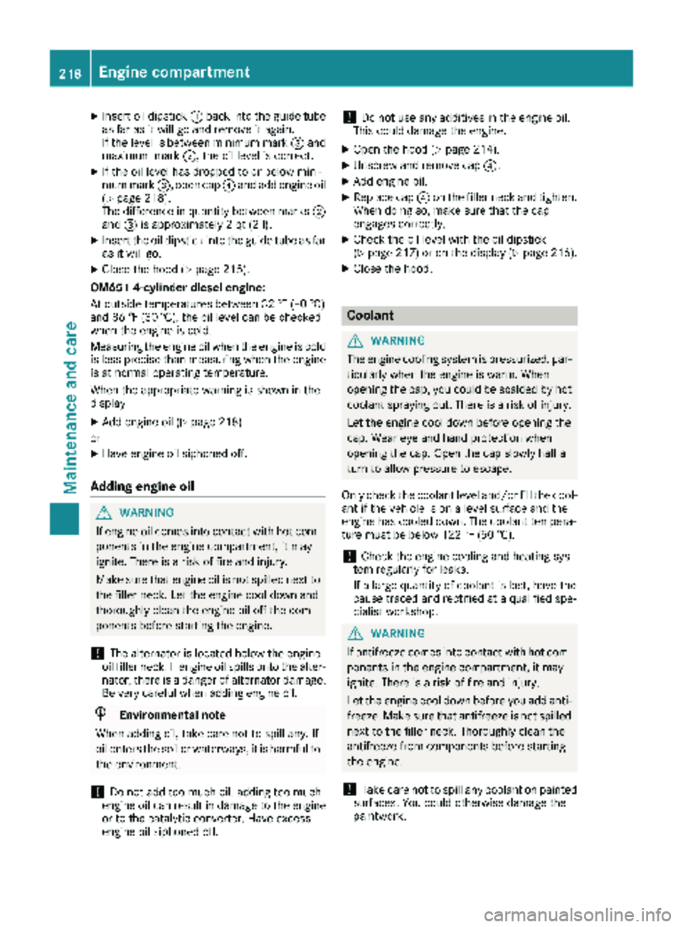
XInsert oil dipstick:back into the guide tube
as far as it will go and remove it again.
If the level is between minimum mark =and
maximum mark ;, the oil level is correct.
XIf the oil level has dropped to or below mini-
mum mark=, open cap ?and add engine oil
(
Ypage 218).
The difference in quantity between marks ;
and =is approximately 2 qt (2 l).
XInsert the oil dipstick into the guide tube as far
as it will go.
XClose the hood (Ypage 215).
OM651 4-cylinder diesel engine:
At outside temperatures between 32 ‡ (–0 †)
and 86 ‡ (30 †), the oil level can be checked
when the engine is cold.
Measuring the engine oil when the engine is cold
is less precise than measuring when the engine
is at normal operating temperature.
When the appropriate warning is shown in the
display
XAdd engine oil (Ypage 218)
or
XHave engine oil siphoned off.
Adding engine oil
GWARNING
If engine oil comes into contact with hot com- ponents in the engine compartment, it may
ignite. There is a risk of fire and injury.
Make sure that engine oil is not spilled next to
the filler neck. Let the engine cool down and
thoroughly clean the engine oil off the com-
ponents before starting the engine.
!The alternator is located below the engine
oil filler neck. If engine oil spills onto the alter-
nator, there is a danger of alternator damage.
Be very careful when adding engine oil.
HEnvironmental note
When adding oil, take care not to spill any. If
oil enters the soil or waterways, it is harmful to
the environment.
!Do not add too much oil. adding too much
engine oil can result in damage to the engine
or to the catalytic converter. Have excess
engine oil siphoned off.
!Do not use any additives in the engine oil.
This could damage the engine.
XOpen the hood (Ypage 214).
XUnscrew and remove cap ?.
XAdd engine oil.
XReplace cap?on the filler neck and tighten.
When doing so, make sure that the cap
engages correctly.
XCheck the oil level with the oil dipstick
(Ypage 217) or on the display (Ypage 216).
XClose the hood.
Coolant
GWARNING
The engine cooling system is pressurized, par-
ticularly when the engine is warm. When
opening the cap, you could be scalded by hot
coolant spraying out. There is a risk of injury.
Let the engine cool down before opening the
cap. Wear eye and hand protection when
opening the cap. Open the cap slowly half a
turn to allow pressure to escape.
Only check the coolant level and/or fill the cool-
ant if the vehicle is on a level surface and the
engine has cooled down. The coolant tempera-
ture must be below 122 ‡ (50 †).
!Check the engine cooling and heating sys-
tem regularly for leaks.
If a large quantity of coolant is lost, have the
cause traced and rectified at a qualified spe-
cialist workshop.
GWARNING
If antifreeze comes into contact with hot com- ponents in the engine compartment, it may
ignite. There is a risk of fire and injury.
Let the engine cool down before you add anti-
freeze. Make sure that antifreeze is not spilled
next to the filler neck. Thoroughly clean the
antifreeze from components before starting
the engine.
!Take care not to spill any coolant on painted
surfaces. You could otherwise damage the
paintwork.
218Engine compartment
Maintenance and care
Page 221 of 286
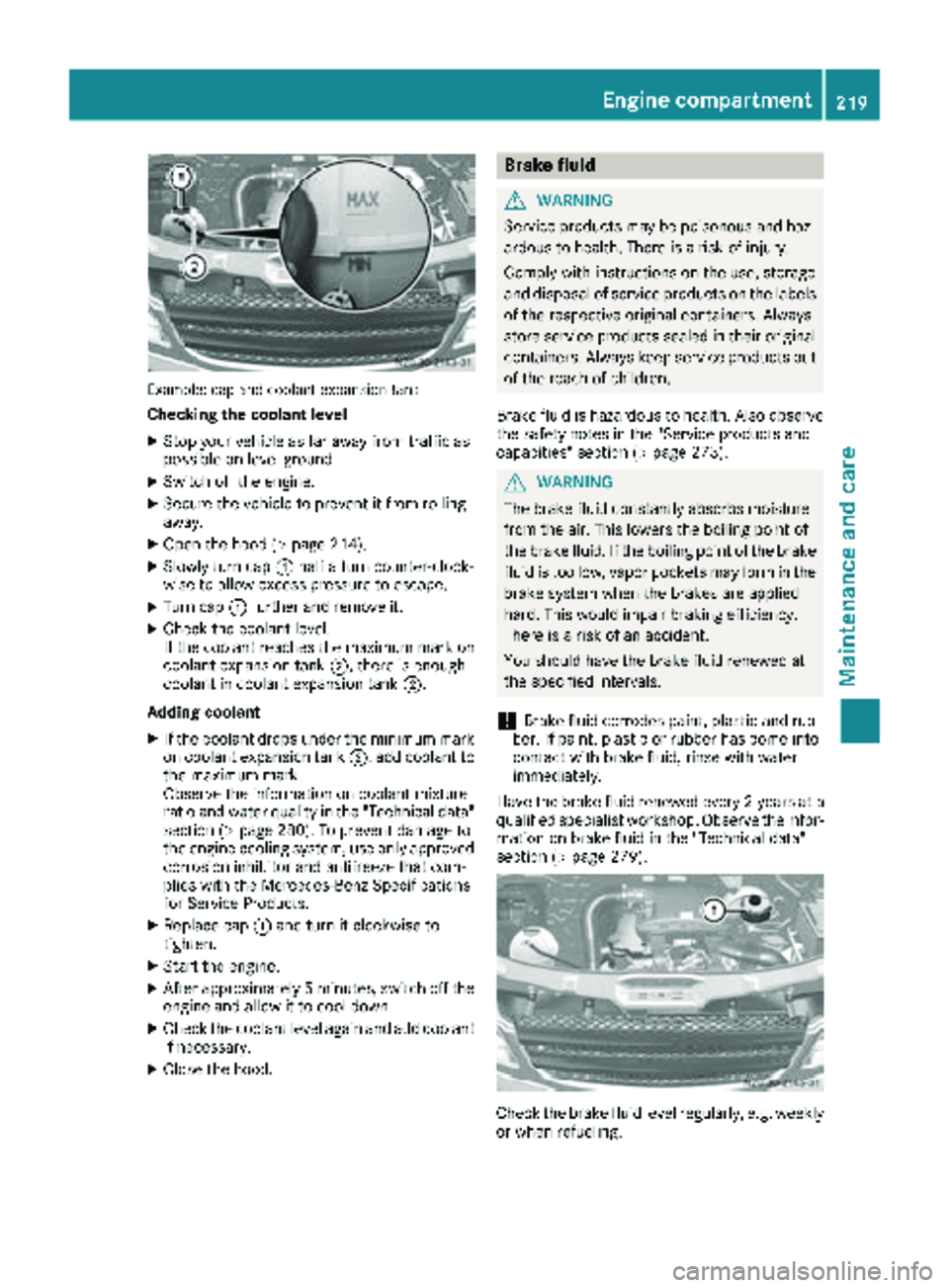
Example: cap and coolant expansion tank
Checking the coolant level
XStop your vehicle as far away from traffic as
possible on level ground.
XSwitch off the engine.
XSecure the vehicle to prevent it from rolling
away.
XOpen the hood (Ypage 214).
XSlowly turn cap:half a turn counter-clock-
wise to allow excess pressure to escape.
XTurn cap :further and remove it.
XCheck the coolant level.
If the coolant reaches the maximum mark on
coolant expansion tank ;, there is enough
coolant in coolant expansion tank ;.
Adding coolant
XIf the coolant drops under the minimum mark
on coolant expansion tank ;, add coolant to
the maximum mark.
Observe the information on coolant mixture
ratio and water quality in the "Technical data"
section (
Ypage 280). To prevent damage to
the engine cooling system, use only approved
corrosion inhibitor and antifreeze that com-
plies with the Mercedes-Benz Specifications
for Service Products.
XReplace cap :and turn it clockwise to
tighten.
XStart the engine.
XAfter approximately 5 minutes, switch off the
engine and allow it to cool down.
XCheck the coolant level again and add coolant
if necessary.
XClose the hood.
Brake fluid
GWARNING
Service products may be poisonous and haz-
ardous to health. There is a risk of injury.
Comply with instructions on the use, storage
and disposal of service products on the labels
of the respective original containers. Always
store service products sealed in their original
containers. Always keep service products out
of the reach of children.
Brake fluid is hazardous to health. Also observe
the safety notes in the "Service products and
capacities" section (
Ypage 273).
GWARNING
The brake fluid constantly absorbs moisture
from the air. This lowers the boiling point of
the brake fluid. If the boiling point of the brake
fluid is too low, vapor pockets may form in the
brake system when the brakes are applied
hard. This would impair braking efficiency.
There is a risk of an accident.
You should have the brake fluid renewed at
the specified intervals.
!Brake fluid corrodes paint, plastic and rub-
ber. If paint, plastic or rubber has come into
contact with brake fluid, rinse with water
immediately.
Have the brake fluid renewed every 2 year sat a
qualified specialist workshop. Observe the infor- mation on brake fluid in the "Technical data"
section (
Ypage 279).
Check the brake fluid level regularly, e.g. weekly
or when refueling.
Engine compartment219
Maintenance and care
Z
Page 222 of 286
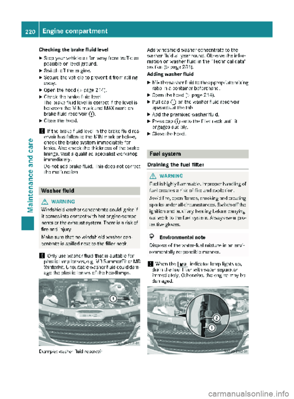
Checking the brake fluid level
XStop your vehicle as far away from traffic as
possible on level ground.
XSwitch off the engine.
XSecure the vehicle to prevent it from rolling
away.
XOpen the hood (Ypage 214).
XCheck the brake fluid level.
The brake fluid level is correct if the level is
between the MIN mark and MAX mark on
brake fluid reservoir:.
XClose the hood.
!If the brake fluid level in the brake fluid res-
ervoir has fallen to the MIN mark or below,
check the brake system immediately for
leaks. Also check the thickness of the brake
linings. Visit a qualified specialist workshop
immediately.
Do not add brake fluid. This does not correct
the malfunction.
Washer fluid
GWARNING
Windshield washer concentrate could ignite if it comes into contact with hot engine compo-
nents or the exhaust system. There is a risk of
fire and injury.
Make sure that no windshield washer con-
centrate is spilled next to the filler neck.
!Only use washer fluid that is suitable for
plastic lamp lenses, e.g. MB SummerFit or MB WinterFit. Unsuitable washer fluid could dam-
age the plastic lenses of the headlamps.
Example: washer fluid reservoir
Add windshield washer concentrate to the
washer fluid all year round. Observe the infor-
mation on washer fluid in the "Technical data"
section (
Ypage 281).
Adding washer fluid
XMix the washer fluid to the appropriate mixing ratio in a container beforehand.
XOpen the hood (Ypage 214).
XPull cap :on the washer fluid reservoir
upwards at the tab.
XAdd the premixed washer fluid.
XPress cap :onto the filler neck until it
engages audibly.
XClose the hood.
Fuel system
Draining the fuel filter
GWARNING
Fuel is highly flammable. Improper handling of
fuel creates a risk of fire and explosion.
Avoid fire, open flames, smoking and creating
sparks under all circumstances. Switch off the
ignition and auxiliary heating before carrying
out work to the fuel system. Always wear pro-
tective gloves.
HEnvironmental note
Dispose of the water-fuel mixture in an envi-
ronmentally responsible manner.
!When the :indicator lamp lights up,
drain the fuel filter with water separator
immediately. Otherwise, the engine may be
damaged.
220Engine compartment
Maintenance and care