fuel cap MERCEDES-BENZ SPRINTER 2018 MY18 Operator’s Manual
[x] Cancel search | Manufacturer: MERCEDES-BENZ, Model Year: 2018, Model line: SPRINTER, Model: MERCEDES-BENZ SPRINTER 2018Pages: 294, PDF Size: 4.36 MB
Page 12 of 294
Driving systemsBlind Spot Assis t............................ 14 3
Cruis econtrol ................................ 13 9
Displa ymessage ............................ 19 1
Lan eKeepin gAssis t...................... 14 5
PARKTRONI C................................. 150
Driving tips
Automati ctransmissio n................ .125
Brakes ...........................................1 34
Break-in period .............................. 118
Checking brake lining thickness .... 135
Downhill gradient ........................... 134
Drinking and driving ....................... 132
Driving abroad ............................... 133
Driving in winter .............................1 36
Driving on flooded roads ................ 136
Driving on wet roads ......................1 36
Exhaust check ............................... 133
Fuel ................................................ 132
General .......................................... 132
Hydroplaning ................................. 136
Icy road surfaces ........................... 136
Important safety notes .................. 118
Limited braking efficiency on sal-
ted roads ....................................... 135
New brake disks ............................ 135
New brake pads/linings ................ 135
Off-road driving .............................. 137
Overrun cut-off .............................. 132
Snow chains .................................. 251
Speed limitation .............................1 33
Towing a trailer .............................. 154
Transport by rail .............................1 34
Wet road surface ........................... 135
DSR (Downhill Speed Regulation) .... 148
E
EBD (electronic brake force distri-
bution)
Display message ............................ 183
Function/notes ................................ 56
Indicator lamps .............................. 196
Electrical closing assist ......................68
Electrical step
Cleaning ........................................ .238
Display message ............................ 194
Emergency release .......................... 68 Function ...........................................6
8
Important safety notes .................... 68
Indicator lamp ................................ 204
Manual retraction ............................ 68
Obstacle detection ........................... 68
Electrical system
Battery main switch ....................... 118
Electronic brake force distribution
see EBD (electronic brake force
distribution)
Electronic Stability Program
see ESP
®(Electronic Stability Program)
Emergency exit .................................... 57
Emergency exit window .....................57
Emergency Tensioning Devices
Activation ........................................ .47
Emissions control
Service and warranty information .... 23
Engine
ADR (working speed governor) ...... 153
Changing the power output ............ .27
Check Engine warning lamp .......... .201
Cleaning instructions ..................... 235
Engine number ............................... 278
Engine speed setting (working
mode) ............................................ 154
Irregular running ............................ 122
Jump-starting ................................. 243
Operating safety .............................. 27
Starting .......................................... 120
Starting problems .......................... 122
Switching off .................................. 131
Tow-starting (vehicle) ..................... 247
Engine electronics
Notes ............................................. 276
Probl
em (malfunction) ................... 122
Engine oil
Adding ...........................................2 23
Additives ........................................ 283
Checking the oil level (on-board
computer) ...................................... 221
Checking the oil level using the
dipstick .......................................... 222
Display message ............................ 191
Filling capacity ............................... 283
Information about oil consump-
tion ................................................ 283
Mixing ............................................ 283
10Index
Page 20 of 294
Removing/mounting ...................... 274
Specia lsea tbelt retractor .................. 49
Specialist worksho p............................ 27
Speed ,controlling
see Cruis econtrol
Speedomete r
Digital (vehicles wit hsteerin g
whee lbuttons ).............................. .169
Digital (vehicles without steering
wheel buttons) ............................... 162
Selecting display unit (vehicles
with steering- wheel buttons) ........1 68
Sprinter dealer
see Qualified specialist workshop
Standing lamps
Replacing bulbs (rear) ......................9 2
Standing lamps (Chassis Cab)
Replacing bulbs (rear) ......................9 3
Start-off assist
Display message ............................1 82
Starting (engine) ................................ 120
Station
see Radio
Steering wheel
Adjusting ......................................... 79
Button overview ............................... 37
Cleaning ......................................... 239
Step
see Electrical step
Stickers
General safety notes ........................ 25
Stowage spaces
see Stowage spaces and stowage
compartments
Stowage spaces and stowage com-
partments
Eyeglasses compartment ...............2 06
Glove box ....................................... 205
Important safety notes .................. 205
Paper holder .................................. 208
Stowage compartment above the
windshield ..................................... 207
Stowage compartment in the cen-
ter console ..................................... 207
Stowage compartment in the
dashboard ...................................... 206
Stowage space above the head-
liner ............................................... 207 Stowage spa
ce under the rear
bench seat ..................................... 208
Stowage space under the twin co-
driver's seat ................................... 207
Summer tires ..................................... 250
Switch unit
see Control panel
Switching off the alarm (ATA) ............ 58
Switching the heater booster func-
tion on/off ......................................... 112
Switching the surround lighting
on/off (on-board computer) ............. 171
Swivel seat ........................................... 75
T
Tachometer ........................................ 161
Tail lamps
Replacing bulbs ............................... 92
Tail lamps (Chassis Cab)
Replacing bulbs ............................... 93
Tank content
Fuel gauge ..................................... 161
Range (vehicles with steering
wheel buttons) ............................... 173
Reserve fuel warning lamp ............. 201
Technical data
Capacities ...................................... 278
Cargo tie-down points .................... 287
Cargo tie-down rings ...................... 287
Loading rails .................................. 287
Roof carrier .................................... 287
Tires/wheels ................................. 273
Trailer tow hitch ............................. 288
Vehicle data ................................... 286
Telephone (on-board computer)
Accepting an incoming call ............ 174
Display messages .......................... 194
Numbers from the phone book ...... 174
Operating ....................................... 173
Redialing ........................................ 174
Rejecting or ending a call .............. 174
Temperature
Outside temperature ...................... 161
Setting (climate control) ................ 103
Setting the unit (vehicles with
steering wheel buttons) ................. 168
18Index
Page 23 of 294
Two-way radiosType approval/frequency .............. 276
TWR (Tongue Weight Rating) (defi-
nition) ................................................. 266
Type plate
Vehicle identification number
(VIN) .............................................. 276
U
UnlockingFrom inside the vehicle (central
unlocking button) ............................. 65
USB port ............................................. 212
V
Vehicle
Data acquisition ............................... 30
Display message ............................ 194
Electronics ..................................... 276
Equipment ....................................... 23
Individual settings (vehicles with
steering wheel buttons) ................. 167
Limited Warranty ............................. 23
Loading .......................................... 259
Locking (SmartKey) .......................... 61
Lowering ........................................ 272
Maintenance .................................... 24
Operating safety .............................. 26
Parking for a long period ................ 131
Pulling away ................................... 121
Raising ........................................... 268
Registration ..................................... 28
Reporting problems ......................... 28
Securing from rolling away ............ 129
Towing away .................................. 244
Transporting .................................. 247
Unlocking (SmartKey) ...................... 61
Vehicle battery
see Battery (vehicle)
Vehicle bodies ..................................... 28
Body/equipment mounting direc-
tives for trucks ................................. 28
Vehicle data ....................................... 286
Vehicle identification number .......... 276
Vehicle identification plate .............. 276
Vehicle tool kit .................................. 241 VIN
...................................................... 276
Voltage supply
Fuses ............................................. 247
W
WarningStickers ........................................... 25
Warning and indicator lamp
Power assistance for the steering .. 204
Warning and indicator lamps
Brakes ........................................... 197
Check Engine ................................. 201
Coolant .......................................... 200
Diesel Exhaust Fluid (DEF) ............. 198
Distance warning function ............. 195
Electrical step ................................ 204
ESP
®.............................................. 195
ESP®function ................................ 199
Lane Keeping Assist ...................... 195
Overview .......................................... 35
Seat belt ........................................ 203
Warning lamp .................................... 242
Warning triangle ................................ 242
Warning- and indicator lamps
ABS ................................................ 196
Air filter .......................................... 202
ASR ................................................ 195
BAS ................................................ 196
Battery charge ............................... 199
Brake wear .................................... 199
Bulbs .............................................. 203
Doors ............................................. 203
Engine oil level ............................... 200
Preglow .......................................... 202
Reserve fuel ................................... 201
Tire pressure monitor .................... 202
Water separator ............................. 203
Windshield washer fluid ................. 203
Warranty .............................................. 23
Washer fluid
Adding ........................................... 225
Capacities ...................................... 286
Display message ............................ 194
Indicator lamp ................................ 203
Notes ............................................. 286
Wiping with ...................................... 96
Index21
Page 27 of 294
Proper use
Observe the following information when oper-
ating your vehicle:
Rthe safety notes in these operating instruc-
tions
Rthe technical data in these Operating Instruc-
tions
Rtraffic laws and regulations
Rmotor vehicle laws and safety standards
There are various warning stickers affixed to the
vehicle. If you remove warning stickers, you and
others may fail to recognize the dangers. Leave
the warning stickers in their original position.
GWARNING
Modifications to electronic components, their software as well as wiring can impair their
function and/or the function of other net-
worked components. In particular, systems
relevant to safety could also be affected. As a
result, these may no longer function as inten-
ded and/or jeopardize the operating safety of
the vehicle. There is an increased risk of an
accident and injury.
Never tamper with the wiring as well as elec-
tronic components or their software. You
should have all work to electrical and elec-
tronic equipment carried out at a qualified
specialist workshop.
The general operating permit for your vehicle
could be rendered invalid if you carry out mod-
ifications to electronic components, their soft-
ware as well as wiring.
GWARNING
Gases and fluids from substances that con-
stitute a health hazard or react aggressively
can escape even from securely closed con-
tainers. When transporting such substances
in the vehicle interior, your ability to concen-
trate or your health could be affected during
the journey. Malfunctions, short circuits or
electrical component system failures may
also result. There is a risk of an accident and
fire.
Do not store or transport any substances in
the vehicle interior which are hazardous to
health or react aggressively.
These instructions must also be observed for
vehicles where the cargo compartment is not
fully separated from the driver's cab.
Partition with door/window: always keep the
door/window in the partition closed during
transport.
Examples of substances that are hazardous to
health and/or react aggressively:
RSolvents
RFuel
ROil and grease
RCleaning agents
RAcids
Protection of the environment
Economic and environmentally aware
driving
HEnvironmental note
Daimler's declared policy is one of compre-
hensive environmental protection.
The objectives are for the natural resources
that form the basis of our existence on this
planet to be used sparingly and in a manner
that takes the requirements of both nature
and humanity into account.
You too can help to protect the environment
by operating your vehicle in an environmen-
tally responsible manner.
Fuel consumption and the rate of engine,
transmission, brake and tire wear are affected
by these factors:
Roperating conditions of your vehicle
Ryour personal driving style
You can influence both factors. You should
bear the following in mind:
Introduction25
Z
Page 38 of 294
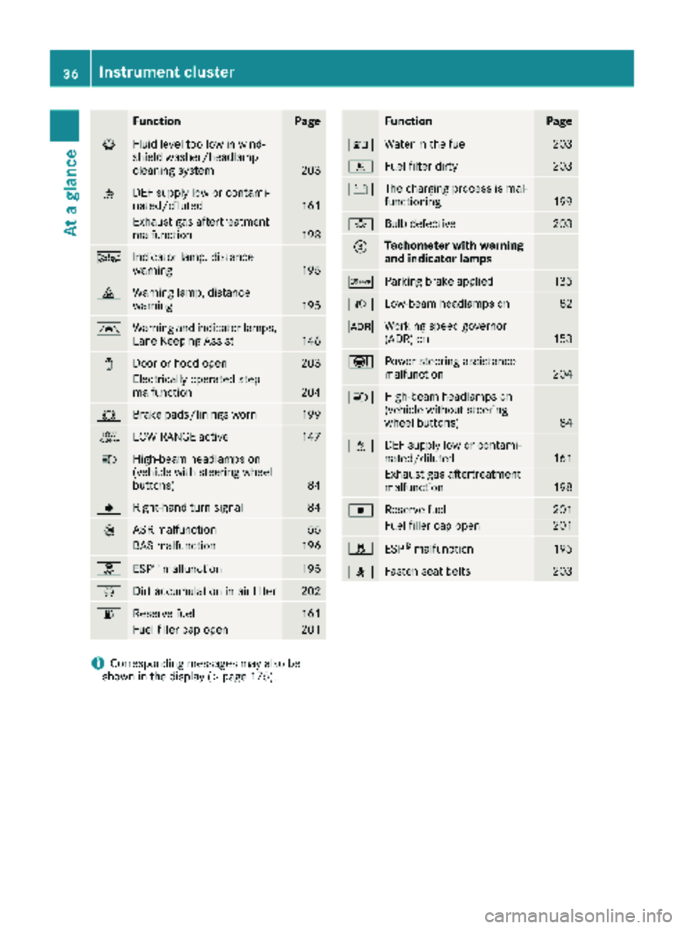
FunctionPage
¦Fluid level too low in wind-
shield washer/headlamp
cleaning system
203
åDEF supply low or contami-
nated/diluted161
Exhaust gas aftertreatment
malfunction198
ÄIndicator lamp, distance
warning195
·Warning lamp, distance
warning195
ÃWarning and indicator lamps,
Lane Keeping Assist146
1Door or hood open203
Electrically operated step
malfunction204
#Brake pads/linings worn199
+LOW RANGE active147
KHigh-beam headlamps on
(vehicle with steering wheel
buttons)
84
JRight-hand turn signal84
:ASR malfunction55
BAS malfunction196
hESP®malfunction195
ÈDirt accumulation in air filter202
6Reserve fuel161
Fuel filler cap open201
FunctionPage
:Water in the fuel203
mFuel filter dirty203
#The charging process is mal-
functioning199
bBulb defective203
=Tachometer with warning
and indicator lamps
cParking brake applied135
LLow-beam headlamps on82
KWorking speed governor
(ADR) on153
ÐPower steering assistance
malfunction204
KHigh-beam headlamps on
(vehicle without steering
wheel buttons)
84
åDEF supply low or contami-
nated/diluted161
Exhaust gas aftertreatment
malfunction198
|Reserve fuel201
Fuel filler cap open201
hESP®malfunction195
7Fasten seat belts203
iCorresponding messages may also be
shown in the display (Ypage 175).
36Instrument cluster
At a glance
Page 110 of 294
GWARNING
When the auxiliary heating is switched on,
parts of the vehicle can become very hot, e.g.
the exhaust system.
Flammable materials such as leaves, grass or
twigs may ignite if they come into contact
with:
Rhot parts of the exhaust system
Rthe exhaust gas itself
There is a risk of fire.
When the auxiliary heating is switched on,
make sure that:
Rno flammable materials come into contact
with hot vehicle components
Rthe exhaust gas can escape from the
exhaust pipe unhindered
Rthe exhaust gas does not come into contact
with flammable materials.
!Turn on the auxiliary heating at least once a
month for approximately 10 minutes. The
auxiliary heating could otherwise be dam-
aged.
!Make sure that the flow of hot air is not
blocked. The auxiliary heating will otherwise
overheat and switch off.
Your vehicle may be equipped with either an
auxiliary hot-water heater or an auxiliary warm-
air heater. Adjustment and operation of the:
Rhot-water auxiliary heater is done via the on-
board computer and with the auxiliary heating
button in the control panel (
Ypage 109) or
with the remote control (Ypage 110).
Rauxiliary warm-air heater is done via the timer
above the overhead control panel
(
Ypage 114).
The auxiliary heating works independently of the
engine and supplements the climate control
system in the vehicle. The auxiliary heating
heats the air in the vehicle interior to the tem-
perature set.
If your vehicle is equipped with a hot-water aux-
iliary heater, the auxiliary heating also keeps the
coolant warm. This way, the load on the engine
is minimized and fuel is saved.
The heater booster function (
Ypage 112) of the
auxiliary heating supports the climate control system when the engine is running and the out-
side temperature is low.
You can use the auxiliary heating at an outside
temperature of up to 39 ‡ (4 †). At an outside
temperature above 39 ‡ (4 †) the auxiliary
heating system and the heater booster function
switch off automatically.
Hot-water auxiliary heating
Heating time
The heating time when operating the auxiliary
heating with the vehicle is stationary without the
engine running depends on the outside temper-
ature and the electrical consumers switched on.
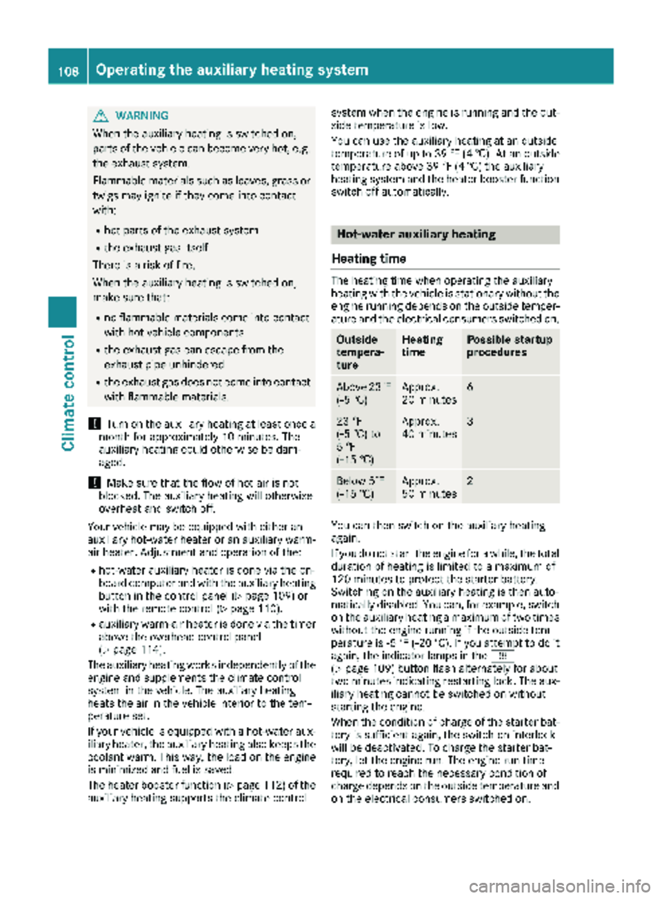
Outside
tempera-
tureHeating
timePossible startup
procedures
Above 23‡
(Ò5 †)Approx.
20 minutes6
23 ‡
(Ò5 †) to
5 ‡
( Ò15 †)Approx.
40 minutes3
Below 5‡
( Ò 15 †)Approx.
50 minutes2
You can then switch on the auxiliary heating
again.
If you do not start the engine for a while, the total
duration of heating is limited to a maximum of
120 minutes to protect the starter battery.
Switching on the auxiliary heating is then auto-
matically disabled. You can, for example, switch
on the auxiliary heating a maximum of two times
without the engine running if the outside tem-
perature is Ò5 ‡ (Ò20 †). If you attempt to do it
again, the indicator lamps in the y
(
Ypage 109) button flash alternately for about
two minutes indicating restarting lock. The aux-
iliary heating cannot be switched on without
starting the engine.
When the condition of charge of the starter bat-
tery is sufficient again, the switch-on interlock
will be deactivated. To charge the starter bat-
tery, let the engine run. The engine run time
required to reach the necessary condition of
charge depends on the outside temperature and
on the electrical consumers switched on.
108Operating the auxiliary heating system
Climate control
Page 129 of 294
and that it is not swallowed. Do not inhale fuelvapors. Keep fuel away from children.
If you or others come into contact with fuel,
observe the following:
RWash away fuel from skin immediately
using soap and water.
RIf fuel comes into contact with your eyes,
immediately rinse them thoroughly with
clean water. Seek medical assistance with-
out delay.
RIf fuel is swallowed, seek medical assis-
tance without delay. Do not induce vomit-
ing.
RImmediately change out of clothing which
has come into contact with fuel.
GWARNING
If you mix diesel fuel with gasoline, the flash
point is lower than that of pure diesel fuel.
When the engine is running, exhaust system
components could overheat without being
noticed. There is a risk of fire.
Never refuel with gasoline. Never mix gasoline with diesel fuel.
HEnvironmental note
If fuels are handled improperly, they pose a
danger to persons and the environment. Do
not allow fuels to run into the sewage system,
the surface waters, the ground water or into
the ground.
!Do not use gasoline to refuel vehicles with a
diesel engine. Even small amounts of gasoline
will cause damage to the fuel system and
engine.
!Do not switch on the ignition if you acciden-
tally refuel with the wrong fuel. Otherwise, the
fuel will enter the fuel lines. Notify a qualified
specialist workshop and have the fuel tank
and fuel lines drained completely.
!Overfilling the fuel tank could damage the
fuel system.
!Take care not to spill any fuel on painted
surfaces. You could otherwise damage the
paintwork.
!Filter the fuel before transferring it to the
vehicle if you are refueling the vehicle from
barrels or containers.
This will prevent malfunctions in the fuel sys-
tem due to contaminated fuel.
Further information on fuel and on fuel grades
can be found in the "Technical data" section
(
Ypage 278).
Refueling procedure
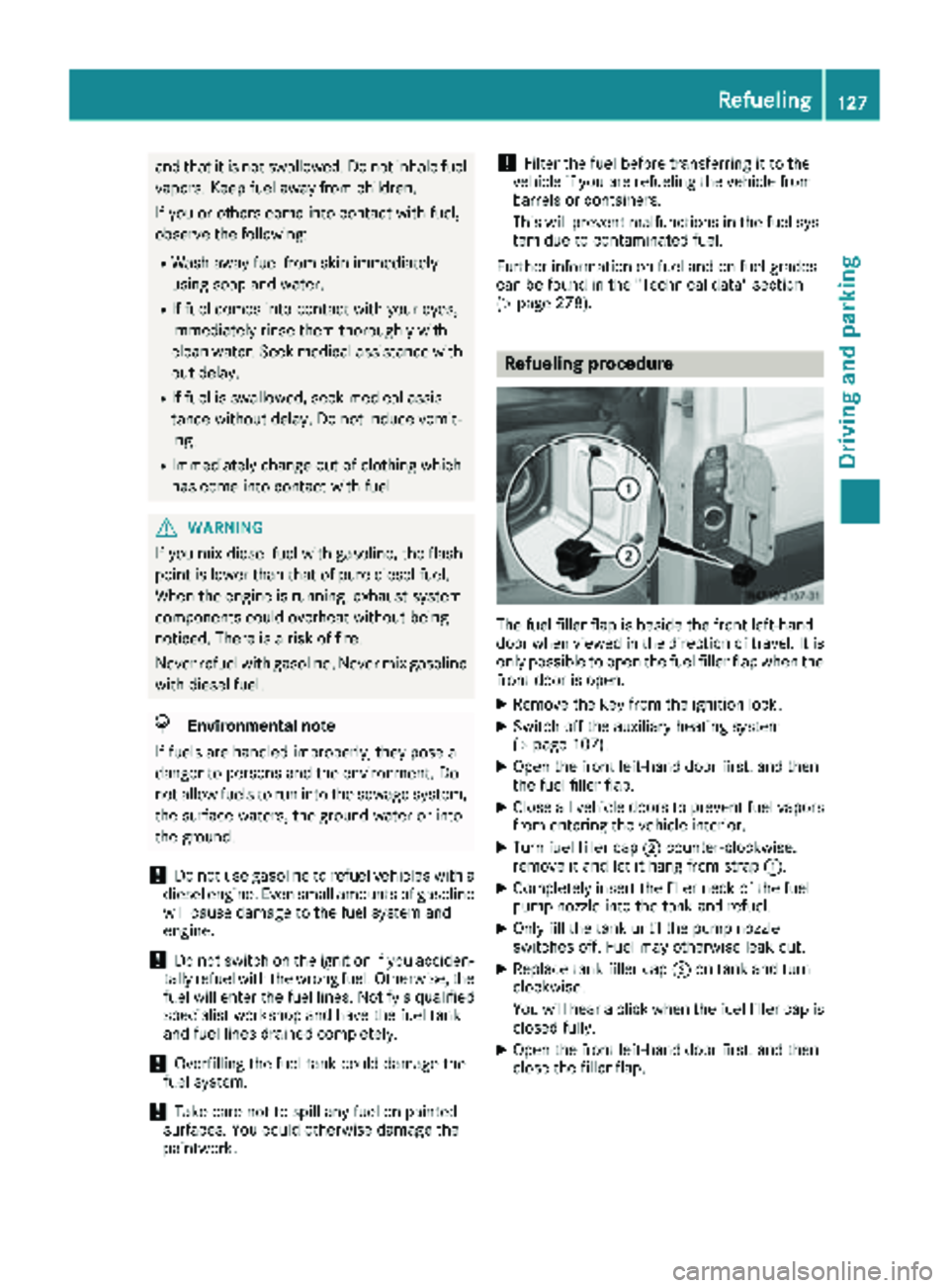
The fuel filler flap is beside the front left-hand
door when viewed in the direction of travel. It is
only possible to open the fuel filler flap when the front door is open.
XRemove the key from the ignition lock.
XSwitch off the auxiliary heating system
(Ypage 107).
XOpen the front left-hand door first, and then
the fuel filler flap.
XClose all vehicle doors to prevent fuel vaporsfrom entering the vehicle interior.
XTurn fuel filler cap ;counter-clockwise,
remove it and let it hang from strap :.
XCompletely insert the filler neck of the fuel
pump nozzle into the tank and refuel.
XOnly fill the tank until the pump nozzle
switches off. Fuel may otherwise leak out.
XReplace tank filler cap;on tank and turn
clockwise.
You will hear a click when the fuel filler cap is
closed fully.
XOpen the front left-hand door first, and then
close the filler flap.
Refueling127
Driving and parking
Z
Page 130 of 294
Problems with the fuel and fuel tank
If your vehicle is losing fuel, the fuel lines or thefuel tank are defective.
XTurn the key immediately to position 0in the
ignition lock and remove it.
XDo not restart the engine under any circum-
stances.
XConsult a qualified specialist workshop.
If the fuel tank has been run dry, after refueling
carry out the following steps:
XBefore starting the engine: switch on the igni-
tion three or four times.
XTurn the key to position 2in the ignition lock
(Ypage 119).
The % preglow indicator lamp in the instru-
ment cluster lights up briefly.
XOnce the %preglow indicator lamp goes
out, turn the key to position 3in the ignition
lock and release it as soon as the engine is
running.
You can start the diesel engine without preglow
when the engine is warm.
Diesel Exhaust Fluid (DEF)
Important safety notes
!Only use DEF in accordance with
ISO 22241. Never mix DEF with additives or
thin it with tap water. The exhaust gas after-
treatment may otherwise be damaged.
Observe the MB Specifications for Service
Products, Sheet 352.0.
Damage that results from the use of additives
or tap water leads to the loss of the New
Vehicle Limited Warranty.
!If DEF comes into contact with a painted or
aluminum surface, wash the surface off
immediately with plenty of water.
!DEF is not a diesel additive and must not be
mixed with fuel in the tank. Even small
amounts of DEF can cause engine damage.
Damage that results from the blending of DEF
will not be covered by the New Vehicle Limi-
ted Warranty.
iIf the outside temperature is below 12 ‡
( Ò 11 †) it may be difficult to top up. If the DEF
is frozen and there is an active warning indi- cator, topping up may not be possible. Park
the vehicle in a warm place, e.g. in a garage,
until the DEF has become liquid again. Top-
ping up is then possible again. Alternatively,
have the DEF tank refilled at a qualified spe-
cialist workshop.
iIf you add DEF at temperatures below 12 ‡
( Ò 11 †) it is possible that the level is not
shown correctly due to the frozen DEF.
Drive for at least 20 minute s(heating phase in
the tank activated) and then st
op the vehicle
for at least 30 seconds. The level is then
shown correctly.
You will find further information on DEF in the
"Service products" section (
Ypage 278).
Refueling procedure
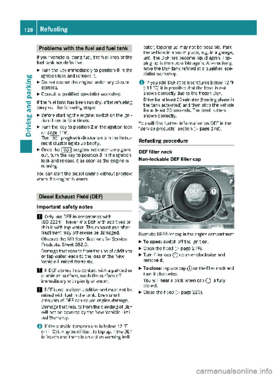
DEF filler neck
Non-lockable DEF filler cap
Example: DEF filler cap in the engine compartment
XTo open: switch off the ignition.
XOpen the hood (Ypage 219).
XTurn filler cap :counter-clockwise and
remove it.
XTo close: replace cap :on the filler neck and
turn it clockwise.
You will hear a click when cap :is fully
closed.
XClose the hood (Ypage 220).
128Refueling
Driving and parking
Page 135 of 294
Do not drink or take drugs and drive or allow
anyone to drive who has been drinking or tak-ing drugs.
Emission control
GWARNING
Combustion engines emit poisonous exhaust
gases such as carbon monoxide. Inhaling
these exhaust gases leads to poisoning. There
is a risk of fatal injury. Therefore never leave
the engine running in enclosed spaces with-
out sufficient ventilation.
Certain engine systems are designed to keep
the level of poisonous substances in exhaust
fumes within legal limits.
These systems only work optimally if they are
maintained exactly in accordance with the man-
ufacturer's specifications. Any work on the
engine should therefore be carried out by quali-
fied and authorized technicians at a Sprinter
dealer.
The engine settings must not be changed under any circumstances. In addition, all specific
maintenance work must be carried out at regu-
lar intervals and in accordance with the service
requirements of the dealer listed here on the
inside title page. Details can be found in the
Maintenance Booklet.
Short journey
!
If the vehicle is predominantly used for
short-distance driving or is stationary for long
periods, this could lead to a malfunction in the automatic cleaning function for the diesel par-
ticle filter. This can lead to blockage of the
diesel particle filter. This can also result in fuel
collecting in the engine oil and cause engine
failure.
Therefore, if you mainly drive short distances,
drive on a highway or an inter-urban road for
20 minute severy 300 miles (500 km). This facil-
itates the diesel particle filter's burn-off proc-
ess.
Speed limiter
GWARNING
Exceeding the stated tire load-bearing capa-
city and the approved maximum speed could
lead to tire damage or the tire bursting. There is a risk of accident.
Therefore, only use tire types and sizes
approved for your vehicle model. Observe the
tire load rating and speed rating required for
your vehicle.
As the driver, you must find out about the max-
imum speed of the vehicle permitted for the
tires (tire and tire pressure). In particular, also
observe the tire approval regulations for each
country.
You must not exceed the speed limit for the tires
listed in the tire pressure tables. You can find
information on tire pressures in the "Wheels and
tires" section (
Ypage 251).
You can permanently limit the speed of your
vehicle to 65 mph (105 km/h) or 75 mph
(120 km/h).
We recommend that you have the speed limit
programmed at an authorized Sprinter dealer.
Before overtaking, take into consideration that
the engine speed limiter prevents the speed
increasing beyond the programmed speed limit.
Driving abroad
Service
An extensive network of authorized Sprinter
Dealers is also at your disposal when you are
traveling abroad. Nevertheless, please bear in
mind that service facilities or replacement parts may not always be immediately available. You
can obtain a list of workshops at any authorized
Sprinter Dealer.
Fuel
In some countries, only fuels with a higher sulfur
content are available.
Unsuitable fuel can cause engine damage. Infor-
mation on fuel (
Ypage 278).
Driving tips133
Driving and parking
Z
Page 157 of 294
nobody is standing between the vehicle and the
trailer.
A trailer which is incorrectly coupled to the tow-ing vehicle could break away. A correctly cou-
pled trailer must be positioned horizontally
behind the towing vehicle.
Ensure that the following weights are not excee-
ded:
Rthe permissible noseweight
Rthe permissible trailer load
Rthe permissible rear axle load of the towing
vehicle
Rthe maximum permissible gross vehicle
weight of both the towing vehicle and the
trailer
Rthe permissible gross combination weight rat-
ing
The applicable permissible values that may not
be exceeded can be found:
Rin your vehicle documents
Ron the type plates for the trailer tow hitch
Ron the type plates for the trailer
Ron the vehicle identification plate
(Ypage 276)
Where the values differ, the lowest is valid.
You will find values approved by the manufac-
turer on the identification plates and those for
the towing vehicle in the "Permissible trailer
loads and trailer drawbar noseweights" section
(
Ypage 158).
Your vehicle behaves differently with a trailer
than without one.
The vehicle/trailer combination:
Ris heavier
Ris restricted in its acceleration and gradient-
climbing capability
Rhas an increased braking distance
Ris more susceptible to strong crosswinds
Rrequires more sensitive steering
Rhas a larger turning circle
This may impair the handling characteristics.
When towing a trailer, always adjust your speed
to suit the road and weather conditions. Drive
carefully. Maintain a safe distance.
If you require any further explanation of the
information contained in the Operator's Manual, please contact an authorized Sprinter dealer.
General notes
RObserve the legally prescribed maximum
speed for vehicle/trailer combinations in the
relevant country, state or Canadian province.Before setting off, check the vehicle docu-
ments of the your trailer to find out the per-
missible maximum speed.
This reduces the risk of accidents.
RInstall only an approved trailer coupling on
your vehicle. Only use a ball coupling that is
approved for your vehicle and Sprinter trailer
tow hitch. More information on the availabil-
ity, mounting and installation of the trailer
electrics is available at any qualified specialist
workshop.
RThe trailer coupling is one of the most impor-
tant vehicle parts with regard to road safety.
The notes on operation, care and mainte-
nance issued by the manufacturer should be
observed.
RThe bumpers of your vehicle are not suitable
for installing detachable trailer couplings.
RDo not attach rented trailer tow hitches or
other detachable trailer tow hitches to the
bumper.
RMinimize the risk of damage to the ball cou-
pling. If you do not require the ball coupling,
remove it from the ball coupling recess.
Weight information can be found in the “Per-
missible trailer and drawbar noseweig hts” se
c-
tion (Ypage 158).
iThe height of the ball neck changes accord-
ing to the load on the vehicle. If this is case,
use a trailer with a height-adjustable trailer
drawbar.
Driving tips
The maximum permissible speed for vehicle/
trailer combination depends on the type of
trailer. Before setting off, check the vehicle
documents of the your trailer to find out the
permissible maximum speed. Observe the
legally prescribed maximum speed for vehicle/
trailer combinations in the relevant country,
state or Canadian province.
When towing a trailer, your vehicle's handling
characteristics will be different in comparison to when driving without a trailer and it will con-
sume more fuel.
On long, steep downhill slopes you must select
shift range 3,2 or 1in good time.
Towing a trailer155
Driving an d parking
Z