buttons MERCEDES-BENZ V-CLASS MPV 2021 User Guide
[x] Cancel search | Manufacturer: MERCEDES-BENZ, Model Year: 2021, Model line: V-CLASS MPV, Model: MERCEDES-BENZ V-CLASS MPV 2021Pages: 337, PDF Size: 9.88 MB
Page 76 of 337
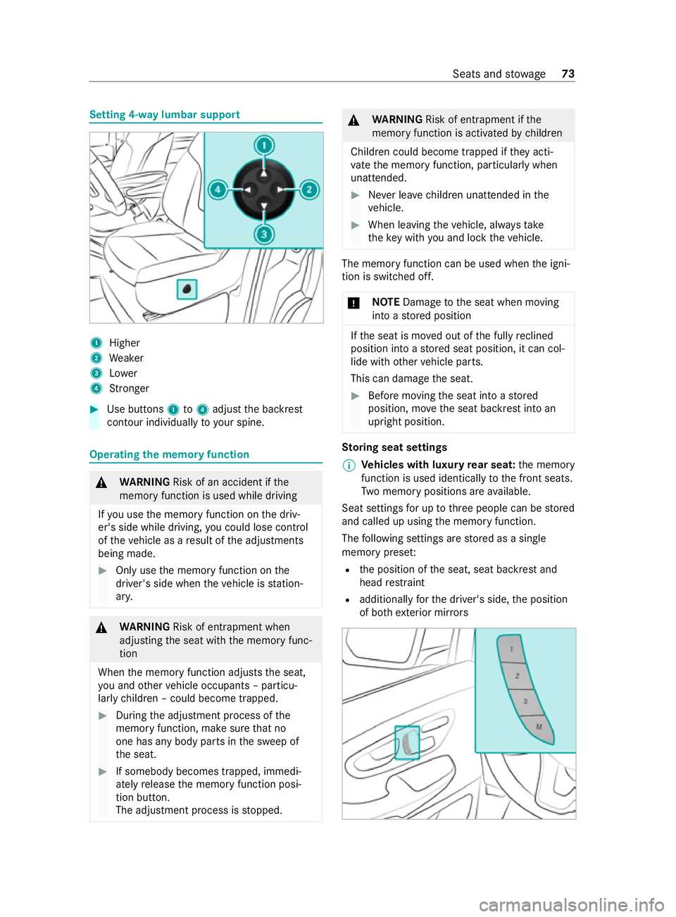
Setting 4-w
aylumbar support 1
Higher
2 Weaker
3 Lower
4 Stronger #
Use buttons 1to4 adjust the backrest
contour individually to your spine. Operating
the memory function &
WARNING Risk of an accident if the
memory function is used while driving
If yo u use the memory function on the driv‐
er's side while driving, you could lose control
of theve hicle as a result of the adjustments
being made. #
Only use the memory function on the
driver's side when theve hicle is station‐
ar y. &
WARNING Risk of entrapment when
adjusting the seat with the memory func‐
tion
When the memory function adjusts the seat,
yo u and other vehicle occupants – particu‐
lar lych ildren – could become trapped. #
During the adjustment process of the
memory function, make sure that no
one has any body parts in the sweep of
th e seat. #
If somebody becomes trapped, immedi‐
ately release the memory function posi‐
tion button.
The adjustment process is stopped. &
WARNING Risk of entrapment if the
memory function is activated bychildren
Children could become trapped if they acti‐
va te the memory function, particularly when
unattended. #
Never lea vechildren unat tended in the
ve hicle. #
When leaving theve hicle, alw aysta ke
th eke y with you and lock theve hicle. The memory function can be used when
the igni‐
tion is switched off.
* NO
TEDama getothe seat when moving
into a stored position If
th e seat is mo ved out of the fully reclined
position into a stored seat position, it can col‐
lide with other vehicle parts.
This can damage the seat. #
Before moving the seat into a stored
position, mo vethe seat backrest into an
upright position. St
oring seat settings
% Ve
hicles with luxury rear seat: the memory
function is used identically tothe front seats.
Tw o memory positions are available.
Seat settings for up tothre e people can be stored
and called up using the memory function.
The following settings are stored as a single
memory prese t:
R the position of the seat, seat backrest and
head restra int
R additionally forth e driver's side, the position
of bo thexterior mir rors Seats and
stowage 73
Page 90 of 337
Re
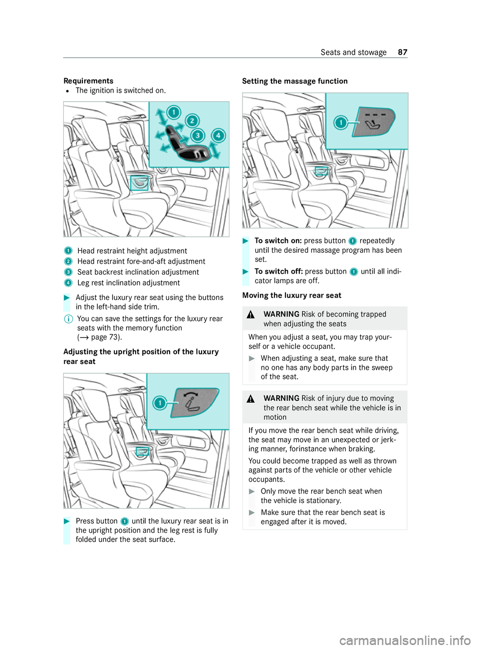
quirements
R The ignition is switched on. 1
Head restra int height adjustment
2 Head restra int fore -and-aft adjustment
3 Seat ba ckrest inclination adjustment
4 Leg rest inclination adjustment #
Adjust the luxury rear seat using the buttons
in the left-hand side trim.
% Yo
u can sa vethe settings forth e luxury rear
seats with the memory function
(/ page 73).
Ad justing the upright position of the luxury
re ar seat #
Press button 1until the luxury rear seat is in
th e upright position and the leg rest is fully
fo lded under the seat sur face. Setting the massage function
#
Toswitch on: press button 1repeatedly
until the desired massage program has been
set. #
Toswitch off: press button 1until all indi‐
cator lamps are off.
Moving the luxu ryrear seat &
WARNING Risk of becoming trapped
when adjusting the seats
When you adjust a seat, you may trap your‐
self or a vehicle occupant. #
When adjusting a seat, make sure that
no one has any body parts in the sweep
of the seat. &
WARNING Risk of injury duetomoving
th ere ar ben chseat while theve hicle is in
motion
If yo u mo vethere ar ben chseat while driving,
th e seat may mo vein an unexpecte d or jerk‐
ing manner, forins tance when braking.
Yo u could become trapped as well as thrown
against parts of theve hicle or other vehicle
occupants. #
Only mo vethere ar ben chseat when
th eve hicle is stationar y. #
Make sure that there ar ben chseat is
engaged af ter it is mo ved. Seats and
stowage 87
Page 96 of 337
&
WARNING Risk of injury duetohead
re stra ints not being fitted or being adjus‐
te d incor rectly
If head restra ints ha venot been ins talled or
ha ve not been adjus ted cor rectly, there is an
increased risk of injury in the head and neck
area, e.g. in theev ent of an accident or when
braking. #
Always drive with the head restra ints fit‐
te d. #
Before driving off, make sure forev ery
ve hicle occupant that the cent reofthe
head restra int supports the back of the
head at about eye le vel. Do not inter
change the head restra ints of the
front and rear seats. Otherwise, you will not be
able toset the height and inclination of the head
re stra ints tothe cor rect position.
Using the head restra int fore -and-aft adjustment,
adjust the head restra int so that it is as close to
th e back of the head as possible. #
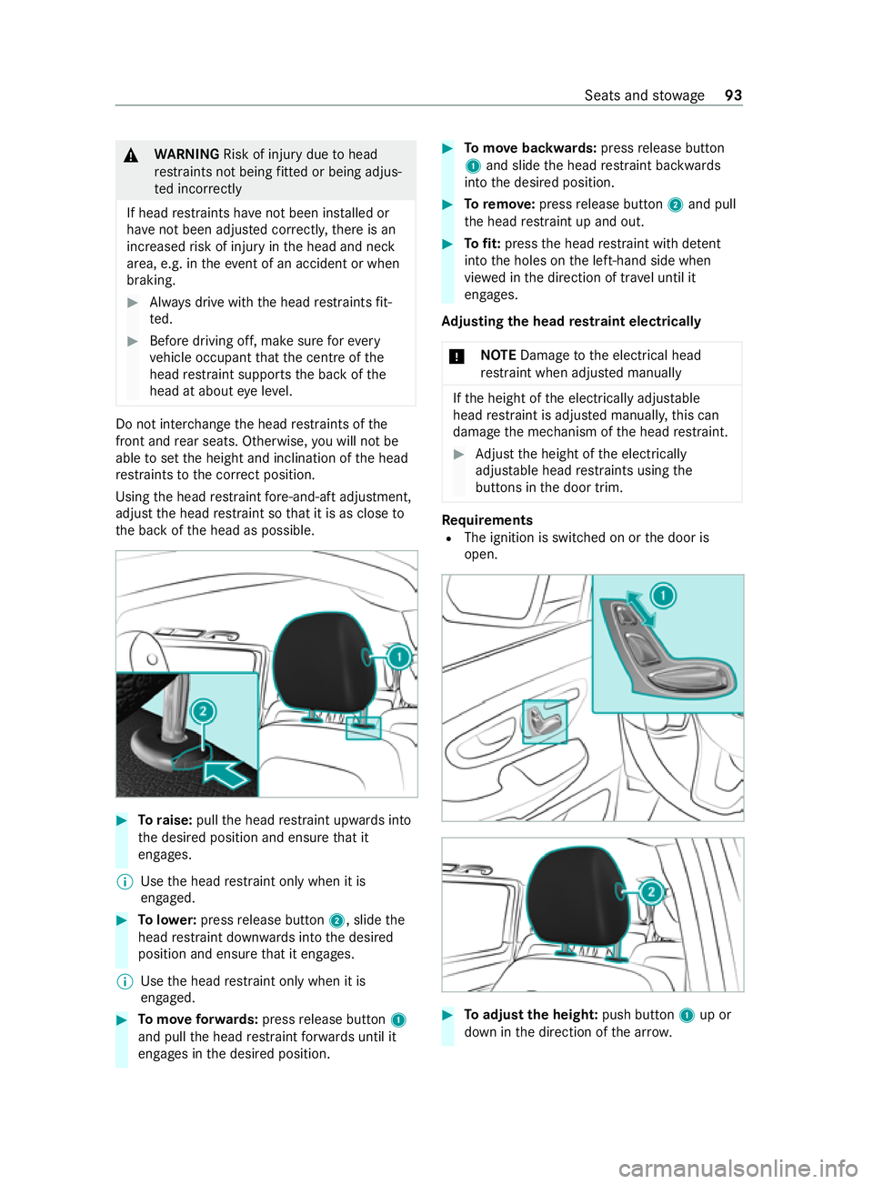
Toraise: pullthe head restra int upwards into
th e desired position and ensure that it
engages.
% Use
the head restra int only when it is
engaged. #
Tolowe r:press release button 2, slidethe
head restra int down wards into the desired
position and ensure that it engages.
% Use
the head restra int only when it is
engaged. #
Tomo veforw ards: press release button 1
and pull the head restra int forw ards until it
engages in the desired position. #
Tomo vebackwards: pressrelease button
1 and slide the head restra int backwards
into the desired position. #
Toremo ve:press release button 2and pull
th e head restra int up and out. #
Tofit: press the head restra int with de tent
into the holes on the left-hand side when
vie we d in the direction of tr avel until it
engages.
Ad justing the head restra int electrically
* NO
TEDama getothe electrical head
re stra int when adjus ted manually If
th e height of the electrically adjus table
head restra int is adjus ted manuall y,this can
damage the mechanism of the head restra int. #
Adjust the height of the electrically
adjus table head restra ints using the
buttons in the door trim. Re
quirements
R The ignition is switched on or the door is
open. #
Toadjust the heigh t:push button 1up or
down in the direction of the ar row. Seats and
stowage 93
Page 114 of 337
deactivated and
the automatic driving lights acti‐
va ted. Ad
justing the in terior lighting Ad
justing the in terior lighting Fr
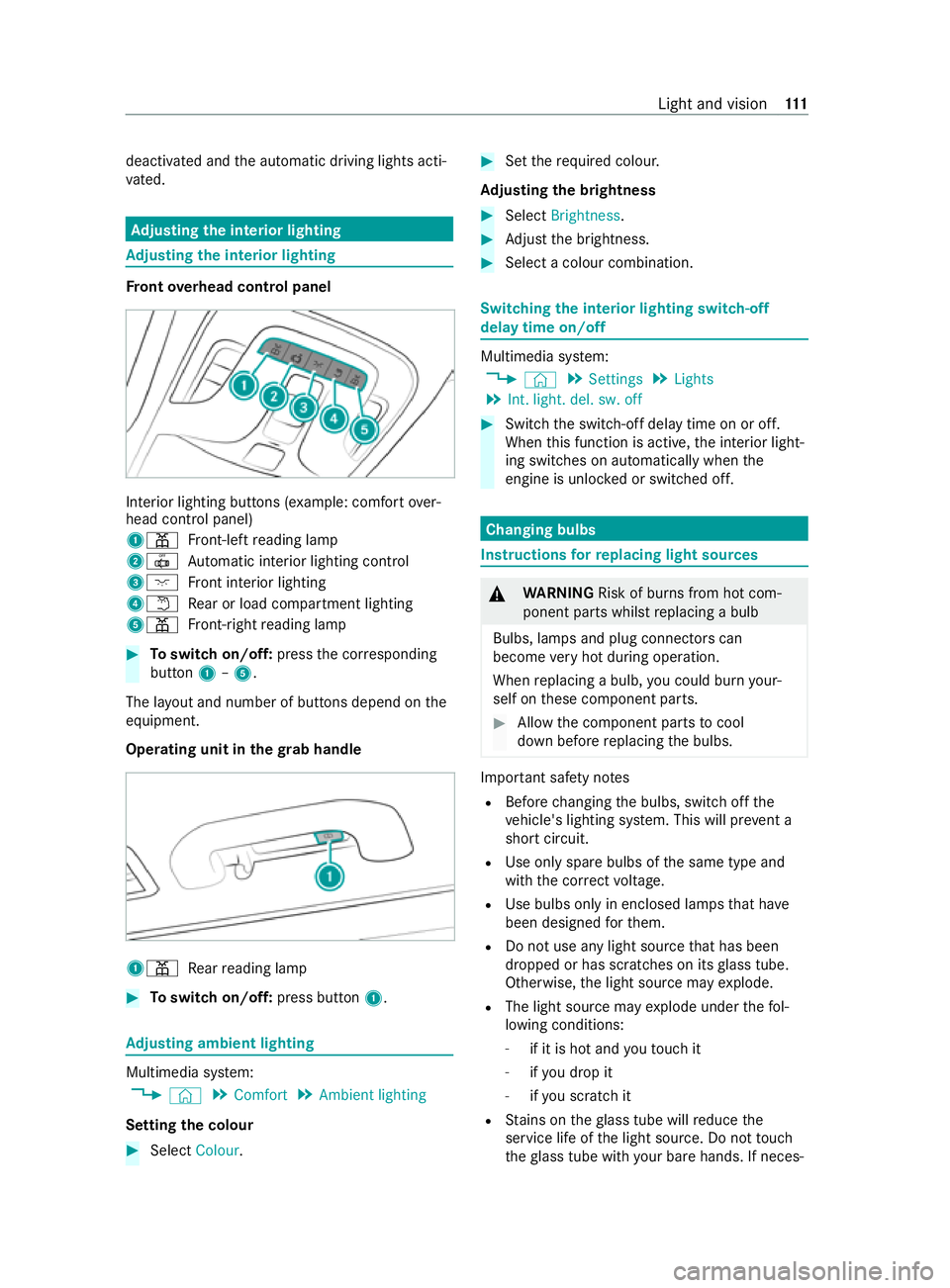
ont overhead control panel In
te rior lighting buttons (e xample: com fort ove r‐
head control panel)
1003D Front-left reading lamp
20033 Automatic interior lighting control
3004A Front interior lighting
40044 Rear or load compartment lighting
5003D Front-ri ghtreading lamp #
Toswitch on/off: pressthe cor responding
button 1–5.
The la yout and number of buttons depend on the
equipment.
Operating unit in thegr ab handle 1003D
Rear reading lamp #
Toswitch on/off: press button1. Ad
justing ambient lighting Multimedia sy
stem:
4 © 5
Comfort 5
Ambient lighting
Setting the colour #
Select Colour. #
Set therequ ired colour.
Ad justing the brightness #
Select Brightness . #
Adjust the brightness. #
Select a colour combination. Switching
the interior lighting switch-off
delay time on/off Multimedia sy
stem:
4 © 5
Settings 5
Lights
5 Int. light. del. sw. off #
Switch the switch-off delay time on or off.
When this function is active, the interior light‐
ing switches on automatically when the
engine is unloc ked or switched off. Changing bulbs
Instructions
forre placing light sou rces &
WARNING Risk of burn s from hot com‐
ponent parts whilst replacing a bulb
Bulbs, lamps and plug connectors can
become very hot during operation.
When replacing a bulb, you could burn your‐
self on these component parts. #
Allow the component parts tocool
down before replacing the bulbs. Impor
tant sa fety no tes
R Before changing the bulbs, switch off the
ve hicle's lighting sy stem. This will pr event a
sho rtcircuit.
R Use only spa rebulbs of the same type and
with the cor rect voltage.
R Use bulbs only in enclosed lamps that ha ve
been designed forth em.
R Do not use any light source that has been
dropped or has scratches on its glass tube.
Otherwise, the light source may explode.
R The light source may explode under thefo l‐
lowing conditions:
- if it is hot and youto uch it
- ifyo u drop it
- ifyo u sc ratch it
R Stains on theglass tube will reduce the
service life of the light source. Do not touch
th eglass tube with your bare hands. If neces‐ Light and vision
111
Page 131 of 337
ru
nfo r appro ximately five more minutes. It will
th en switch off automaticall y.
When the auxiliary heating is heating and the
engine is star ted, the heater boos ter function of
th e auxiliary heating will be activated.
When the auxiliary heating is ventilating and the
engine is star ted, the auxiliary heating will be
automatically switched off.
Switching the hot- water auxiliary hea ter
on/off with the but ton
Requ irements
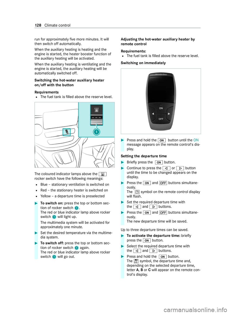
R The fuel tank is filled abo vethere ser veleve l. The coloured indicator lamps abo
vethe003B
rock er switch ha vethefo llowing meanings:
R Blue – stationary ventilation is switched on
R Red – thest ationary heater is swit ched on
R Yellow – a departure time is preselec ted#
Toswitch on: presstheto p or bottom sec‐
tion of rocker switch 1.
The red or blue indicator lamp abo verock er
switch 1will light up.
The multimedia sy stem will be activated for
appr oximately one minute. #
Set the desired temp erature via the multime‐
dia sy stem. #
Toswitch off: presstheto p or bottom sec‐
tion of rocker switch 1again.
The red or blue indicator lamp abo verock er
switch 1will go out. Ad
justing the hot-water auxiliary hea terby
re mo tecontrol
Re quirements:
R The fuel tank is filled abo vethere ser veleve l.
Switching on immediately #
Press and hold the008B button until theON
message appears on there mo tecontrol's dis‐
pla y.
Setting the departu retime #
Brie fly press the 008B button. #
Continue topress the006A or0066 button
until the time tobe changed appears on the
displa y. #
Press the008B and0078 buttons simultane‐
ously.
The 004Dsymbol on there mo tecontrol display
will flash. #
Set therequ ired departure time with
th e006A and0066 buttons. #
Press the008B and0078 buttons simultane‐
ously.
The new departure time will be sa ved.
Up tothre e departure times can be sa ved. #
Toactivate the departu retime: briefly
press the008B button. #
Select there qu ired departure time with
th e006A and0066 buttons. #
Press and hold the 008B button.
The 004Csymbol, the departure time and,
depending on the selected departure time,
letter A,Bor Cwill appear on there mo tecon‐
trol's displa y. 12 8
Climate cont rol
Page 136 of 337
R
Lights up green – auxiliary heating switched
on
R Flashes green – change operating duration
option active
R Flashes alternately red and green – remo te
control in synchronising mode
When there mo tecontrol battery is weak, indica‐
to r lamp 1will flash redra pidl y. #
Replace there mo tecontrol battery
(/ page 132).
% Yo
u can find fur ther information on lamp sta‐
tuses under "Problems with the auxiliary
heating" .
Switching there mo tecontrol on/off
The remo tecontrol will switch tostandby mode
af te rte n seconds. Indicator lamp 1will go out. #
Toswitch on: press and hold the00D0 but‐
to n until indica tor lamp 1lights up red. #
Toswitch off: press and hold button 00D0
until indicator lamp 1goes out.
Switching auxiliary heating on and off #
Switch on there mo tecontrol. #
Toswitch on: when indicator lamp 1
fl ashes red, press the0076 button.
During data transfer, indicator lamp 1will
light up red.
When indicator lamp 1lights up green, the
auxiliary heating is swit ched on. #
Toswitch off: when indicator lamp 1lights
up green, press the0076 button.
During data transfer, indicator lamp 1will
light up red.
When indicator lamp 1flashes red, the aux‐
iliary heating is switched off.
Changing the operating du ration #
Switch on there mo tecontrol. #
When indicator la mp1flashes red, press
th e00D0 and0076 buttons simultaneousl y.
Indicator lamp 1will flash green. #
Press the00D0 button repeatedly until the
desired operating duration is shown. R 20 minutes – indicator lamp 1will flash
green tw ice.
R 30 minutes – indicator lamp 1will flash
green thre e times.
R 40 minutes – indicator lamp 1will flash
green four times. #
Press the0076 button.
During data transfer, indicator lamp 1will
light up red.
When indicator lamp 1emits two long,
green flashes, the selected operating duration
is stored.
If no adjustment is made tothe operating
duration, indicator lamp 1will flash six
times and there mo tecontrol will enter
st andby mode.
Re placing the remo tecontrol bat tery (auxili‐
ary warm-air heater) &
DANG ER Risk of fata l injuries due to
swallowing batteries
Batteries contain toxic and cor rosive subs tan‐
ces. Swallowing batteries may cause se vere
internal burns within two hours.
There is a risk of fata l injuries. #
Keep batteries out of there ach of chil‐
dren. #
Ifth e battery co ver does not close
securely, do not continue touse the
re mo tecontrol, and keep it out of the
re ach of children. #
If batteries are swallo wed, seek medical
attention immediately. +
ENVIRONMEN
TALNO TEEnvironmental
damage due toimproper disposal of bat‐
te ries Batteries contain
toxic and cor ro‐
sive subs tances. #
Ta
ke dischar ged batteries to
a qu alified specialist workshop or to a
collection point for used batteries. Re
quirements
R A CR2430 lithium battery is available.
Mercedes-Benz recommends that you ha vethe
battery replaced byaqu alified specialist work‐
shop. Climate
control 13 3
Page 184 of 337
Coolant
temperature display &
WARNING Risk of burn s when opening
th e bonn et
If yo u open the bonn etwhen the engine has
ove rheated or when there is a fire inthe
engine compartment, thefo llowing situations
may occur:
R You could come into con tact with hot
ga ses.
R You could come into con tact with other
hot, escaping operating fluids. #
Before opening the bonn et, allow the
engine tocool down. #
Intheeve nt of a fire inthe engine com‐
partment, keep the bonn etclosed and
call thefire service. The coolant
temp erature display is located within
th e instrument clus ter's rev counter.
During normal driving and if the coolant le vel is
cor rect, the display is permitted torise to120°C. Overview and operation of
the on-boa rd
compu ter &
WARNING Risk of distraction from infor‐
mation sy stems and communications
equipment
If yo u operate information and communica‐
tion equipment integ rated in theve hicle when
driving, you will be distracted from the tra ffic
situation. This could also cause youto lose
control of theve hicle. #
Only operate this equipment when the
traf fic situation permits. #
Ifyo u cannot be sure of this, stop the
ve hicle whilst paying attention toroad
and traf fic conditions and ope rate the
equipment with theve hicle stationar y. Yo
u must obse rveth e legal requirements forthe
country in whi chyou are cur rently driving when
ope rating the on-board computer. 1
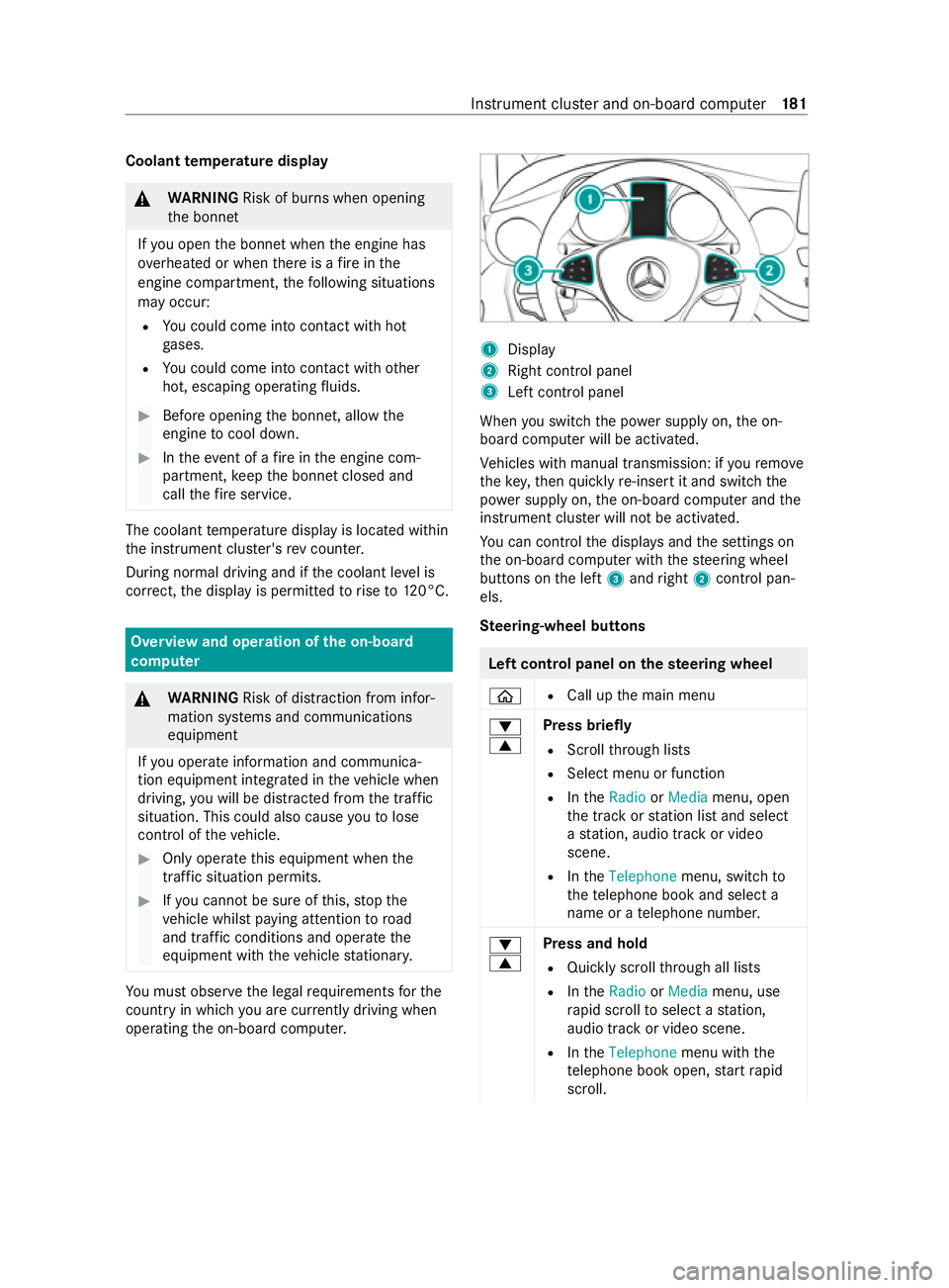
Display
2 Right contro l panel
3 Left control panel
When you swit ch the power supply on, the on-
board computer will be activated.
Ve hicles with manual transmission: if youre mo ve
th eke y,then quickly re-inse rtit and switch the
po we r supp lyon, the on-board computer and the
instrument clus ter will not be activated.
Yo u can control the displa ysand the settings on
th e on-board computer with thesteering wheel
buttons on the left 3and right 2contro l pan‐
els.
Ste ering-wheel but tons Left control panel on
thest eering wheel
00E2 R
Call up the main menu
0064
0063 Press briefly
R Scroll thro ugh lists
R Select menu or function
R IntheRadio orMedia menu, open
th e tra ckorstation list and select
a st ation, audio track or video
scene.
R IntheTelephone menu, switch to
th ete lephone book and select a
name or a telephone numbe r.
0064
0063 Press and hold
R Quickly scroll thro ugh all lists
R IntheRadio orMedia menu, use
ra pid scroll toselect a station,
audio track or video scene.
R IntheTelephone menu with the
te lephone book open, start rapid
scroll. Instrument clus
ter and on-board computer 181
Page 198 of 337
Home screen
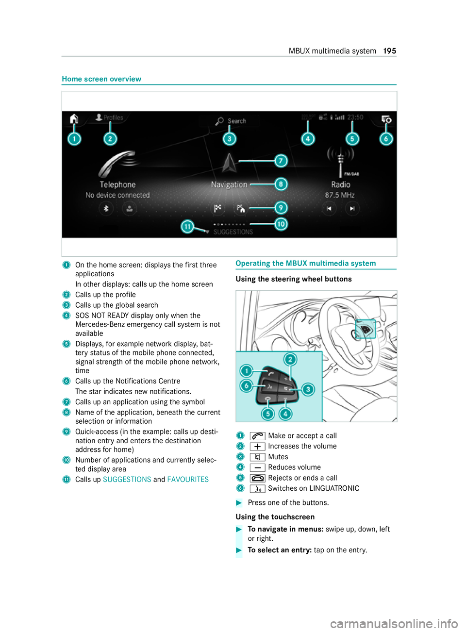
overview 1
Onthe home screen: displa ys thefirs tth ree
applications
In other displa ys: calls up the home screen
2 Calls up the profile
3 Calls up theglobal sear ch
4 SOS NOT READY displ ayonly when the
Mercedes-Benz emer gency call sy stem is not
av ailable
5 Displa ys,fo rex ample network displa y,bat‐
te ry status of the mobile phone connected,
signal stre ngth of the mobile phone networ k,
time
6 Calls up the Notifications Centre
The star indicates new notifications.
7 Calls up an application using the symbol
8 Name of the application, beneath the cur rent
selection or information
9 Quick-access (in theex ample: calls up desti‐
nation ent ryand enters the destination
address for home)
A Number of applications and cur rently selec‐
te d display area
B Calls up SUGGESTIONS andFAVOURITES Operating
the MBUX multimedia sy stem Using
thest eering wheel but tons 1
0061 Make or accept a call
2 0081 Increases thevo lume
3 0063 Mutes
4 0082 Reduces volume
5 0076 Rejects or ends a call
6 00E3 Switches on LING UATRONIC #
Press one of the buttons.
Using theto uchscreen #
Tonavigate in menus: swipe up, down, left
or right. #
Toselect an entr y:tap on the entry. MBUX multimedia sy
stem 19 5
Page 199 of 337
#
Toenter characters with theke yboard: tap
on a button. #
Touse handwriting toenter characters:
write thech aracter with one finger on the
to uchsc reen. #
Tozoom in and out of the map: movetwo
fi ngers toget her or apart. #
Toenlar georreduce the size of a section
of a website: movetwo fingers toget her or
apart. #
Tocall up a global menu in the applica‐
tions: touch theto uchsc reen and hold until
th eOPTIONS menu appears.
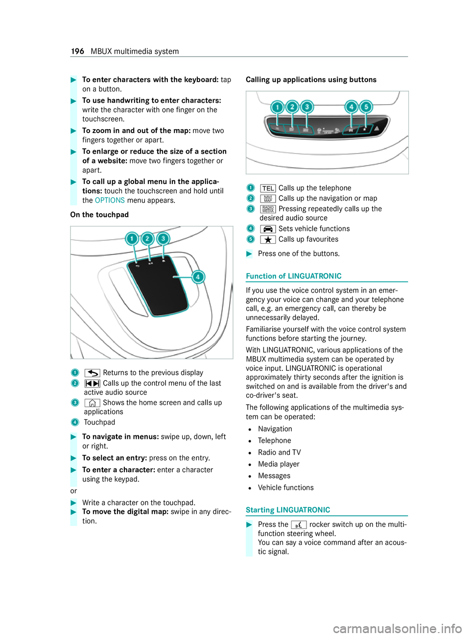
On theto uchpad 1
G Returns tothe pr evious display
2 ~ Calls up the cont rol menu of the last
active audio source
3 © Shows th e home screen and calls up
applications
4 Touchpad #
Tonavigate in menus: swipe up, down, left
or right. #
Toselect an entr y:press on the entry. #
Toenter a character: enter acharacter
using theke ypad.
or #
Write a character on theto uchpad. #
Tomo vethe digital map: swipe in any direc‐
tion. Calling up applications using butto
ns 1
002B Calls up thete lephone
2 z Calls up the navigation or map
3 | Pressing repeatedly calls up the
desired audio source
4 00CE Setsvehicle functions
5 ß Calls up favo urites #
Press one of the buttons. Fu
nction of LINGU ATRO NIC If
yo u use thevo ice control sy stem in an emer‐
ge ncy your voice can change and your telephone
call, e.g. an emer gency call, can thereby be
unnecessarily dela yed.
Fa miliarise yourself with thevo ice control sy stem
functions before starting the journe y.
Wi th LINGU ATRO NIC, various applications of the
MBUX multimedia sy stem can be operated by
vo ice input. LINGU ATRO NIC is operational
appr oximately thirty seconds af terth e ignition is
switched on and is available from the driver's and
co-driver's seat.
The following applications of the multimedia sys‐
te m can be operated:
R Navigation
R Telephone
R Radio and TV
R Media pla yer
R Messages
R Vehicle functions St
arting LING UATRONIC #
Press the£ rocker switch up on the multi‐
function steering wheel.
Yo u can say a voice command af ter an acous‐
tic signal. 19 6
MBUX multimedia sy stem
Page 210 of 337
Yo
u can inter change the mobile phone in
th efo re ground and bac kground.
Connecting a mobile phone
Re quirements:
R Blue tooth ®
is activated on the mobile phone
(see the manufacturer's operating instruc‐
tions).
R Blue tooth ®
is activated on the multimedia
sy stem.
Multimedia sy stem:
4 © 5
Phone
Sear ching for a mobile phone #
Select í. #
Select Connect new device.
Connecting a mobile phone
Auth orisation follo ws using secure simple pairing. #
Select a mobile phone.
A code is displ ayed in the multimedia sy stem
and on the mobile phone. #
If bo thcodes match, confirm the code on the
mobile phone.
Fu nctions in theTe lephony menu
The functions available in theTe lephony menu
include thefo llowing:
R Making calls, e.g.:
- R Accepting a call
- k End call
- i Create conferen. call
- Accepting or rejecting a waiting call
R Managing con tacts, e.g.:
- Downloading mobile phone contacts
- Editing thefo rm at of a con tact's name
- Saving contacts in theve hicle
R Receiving and sending messages, e.g.:
- Using there ad-aloud function
- Dictating a new messa ge Overview of Smartphone Integ
ration
Wi th Smartphone Integration, you can use cer tain
functions on your mobile phone via the multime‐
dia sy stem displa y.
Only one mobile phone at a time can be connec‐
te d via Smartphone Integration tothe multimedia
sy stem. Also for use with two phone mode with smartphone integration, only one additional
mobile phone can be connected using Blue
tooth®
with the multimedia sy stem.
The full range of functions for Smartphone Inte‐
gration is only possible with an Internet connec‐
tion. The appro priate application must be down‐
loaded on the mobile phone touse Smartphone
In te gration. The mobile phone must be switched
on and connected toa USB port with theç
symbol on the multimedia sy stem using a suita‐
ble cable.
Apps for Smartphone Integration
R Apple CarPlay ®
R Android Auto
Yo u can start Apple CarPlay ®
or Android Auto
using theApps menu.
Alternative: If an application is active via Smart‐
phone Integration (e.g. when music is being
pla yed or route guidance is active), you can call
up the active application using the| orz
or 002B application buttons
Yo u can end Smartphone In tegr ation bydiscon‐
necting the connecting cable between the mobile
phone and multimedia sy stem.
% Mercedes-Benz
recommends disconnecting
th e connecting cable only when theve hicle is
st ationar y.
When using Android Autoor Apple CarPlay ®
, cer‐
ta in vehicle data is transfer redto the mobile
phone. This enables youto getth e best out of
selected mobile phone services. Vehicle data is
not directly accessible.
The following sy stem information is transmit ted:
R Software release of the multimedia sy stem
R System ID (anonymised)
The transfer of this data is used tooptimise com‐
munication between theve hicle and the mobile
phone.
To do this, and toassign se veralve hicles tothe
mobile phone, a vehicle ID is randomly gener‐
ated.
This has no connection totheve hicle identifica‐
tion number (VIN) and is dele ted when the multi‐
media sy stem is reset (/ page 200). MBUX multimedia sy
stem 207