steering MERCEDES-BENZ V-CLASS MPV 2021 Owner's Manual
[x] Cancel search | Manufacturer: MERCEDES-BENZ, Model Year: 2021, Model line: V-CLASS MPV, Model: MERCEDES-BENZ V-CLASS MPV 2021Pages: 337, PDF Size: 9.88 MB
Page 177 of 337
When
thewa rning function is active and you pass
a traf fic sign, the instrument clus ter sho wsthe
traf fic re gulations (speed limit and overtaking
re striction) forfive seconds. The pr evious menu
th en reappears automaticall y.
The wrong-w aywarning remains active if you
deactivate thewa rning function of Traf fic Sign
Assi st. Blind Spot Assist
Fu
nction of Blind Spot Assist
Blind Spot Assist uses two lateral, rear-facing
ra dar sensors tomonitor the area up to3 m
behind and 3 m directly next to yourvehicle. &
WARNING Risk of accident despite Blind
Spot Assi st
Blind Spot Assist does not react toeither sta‐
tionary objects or vehicles approaching and
ove rtaking you at a greatly di fferent speed.
Blind Spot Assist cann otwa rndrivers in these
situations. #
Always pay careful attention tothe traf‐
fi c situation and maintain a safe dis‐
ta nce at the side of theve hicle. Obser
vethe no tes on driving sy stems and your
re sponsibility; you may otherwise failto recog‐
nise dangers (/ page 153).
If a vehicle is de tected above speeds of appr ox‐
imately 30 km/h and this vehicle subsequently
enters the monitoring range di rectly next toyour
ve hicle, thewa rning lamp in the outside mir ror
lights up red.
If a vehicle is de tected close to yourvehicle in the
lateral monitoring range and you swit chon the
turn signal indica tor in the cor responding direc‐
tion, a warning tone sounds. The redwa rning
lamp in the outside mir rorflashes. If the turn sig‐
nal indicator remains switched on, all other
de tected vehicles are indicated only bytheflash‐
ing of there dwa rning lamp.
When youove rtake a vehicle, thewa rning only
occurs if the dif fere nce in speed is less than
11 km/h. Sy
stem limits
Blind Spot Assist may be limited in thefo llowing
situations:
R ifth ere is dirt on the sensors or the sensors
are obscured
R ifth ere is poor visibility, e.g. due tofog, heavy
ra in, snow or spr ay
R if nar rowvehicles are within the monitoring
ra nge, e.g. bicycles
R ifth ero ad has very wide or very nar row lanes
R ifve hicles are not driving in the middle of
th eir lane
Wa rnings may be issued in er ror when driving
close tocrash barr iers or similar solid lane bor‐
ders. Warnings may be inter rupte d when driving
alongside long vehicles, forex ample lor ries, for a
prolonged time.
Blind Spot Assist is not operational when reve rse
ge ar is engaged.
If yo u couple up a trailer, make sure that you ha ve
cor rectly es tablished the electrical connection.
Blind Spot Assist is then deactivated and the
Blind Spot Assist currently unavailable See Own-
er's Manual message appea rsinthe multifunc‐
tion displa y.
Ac tivating/deactivating Blind Spot Assi st
On-board computer:
4 00E2 5
Settings 5
Assistance
5 Blind Spot Assist #
Toactivate/deactivate: pressthe0076 but‐
to n.
When Blind Spot Assi stis activated, grey radar
wav es propagating backwards appear next tothe
ve hicle in the assis tance graphic in the multifunc‐
tion displa y.Ifyo u drive fasterthan 30 km/h with
Blind Spot Assist activated, thera dar waves in
th e assis tance graphic appear green. Blind Spot
Assi stisready for use.
If yo u swit chon the ignition while Blind Spot
Assist is activated, thewa rning lamps in the out‐
side mir rors light up for appro x.1.5 seconds. Lane
Keeping Assist Fu
nction of Lane Keeping Assist
Lane Keeping Assist ser vesto protect you against
unin tentionally le aving your lane. You are also
wa rned bya vibration in thesteering wheel and
by thest atus symbol flashing in the instrument 174
Driving and pa rking
Page 184 of 337
Coolant
temperature display &
WARNING Risk of burn s when opening
th e bonn et
If yo u open the bonn etwhen the engine has
ove rheated or when there is a fire inthe
engine compartment, thefo llowing situations
may occur:
R You could come into con tact with hot
ga ses.
R You could come into con tact with other
hot, escaping operating fluids. #
Before opening the bonn et, allow the
engine tocool down. #
Intheeve nt of a fire inthe engine com‐
partment, keep the bonn etclosed and
call thefire service. The coolant
temp erature display is located within
th e instrument clus ter's rev counter.
During normal driving and if the coolant le vel is
cor rect, the display is permitted torise to120°C. Overview and operation of
the on-boa rd
compu ter &
WARNING Risk of distraction from infor‐
mation sy stems and communications
equipment
If yo u operate information and communica‐
tion equipment integ rated in theve hicle when
driving, you will be distracted from the tra ffic
situation. This could also cause youto lose
control of theve hicle. #
Only operate this equipment when the
traf fic situation permits. #
Ifyo u cannot be sure of this, stop the
ve hicle whilst paying attention toroad
and traf fic conditions and ope rate the
equipment with theve hicle stationar y. Yo
u must obse rveth e legal requirements forthe
country in whi chyou are cur rently driving when
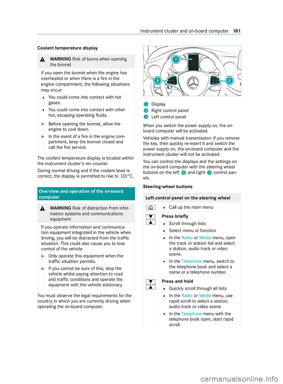
ope rating the on-board computer. 1
Display
2 Right contro l panel
3 Left control panel
When you swit ch the power supply on, the on-
board computer will be activated.
Ve hicles with manual transmission: if youre mo ve
th eke y,then quickly re-inse rtit and switch the
po we r supp lyon, the on-board computer and the
instrument clus ter will not be activated.
Yo u can control the displa ysand the settings on
th e on-board computer with thesteering wheel
buttons on the left 3and right 2contro l pan‐
els.
Ste ering-wheel but tons Left control panel on
thest eering wheel
00E2 R
Call up the main menu
0064
0063 Press briefly
R Scroll thro ugh lists
R Select menu or function
R IntheRadio orMedia menu, open
th e tra ckorstation list and select
a st ation, audio track or video
scene.
R IntheTelephone menu, switch to
th ete lephone book and select a
name or a telephone numbe r.
0064
0063 Press and hold
R Quickly scroll thro ugh all lists
R IntheRadio orMedia menu, use
ra pid scroll toselect a station,
audio track or video scene.
R IntheTelephone menu with the
te lephone book open, start rapid
scroll. Instrument clus
ter and on-board computer 181
Page 185 of 337

Left control panel on
thest eering wheel
0076 R
In all menus, con firm the selected
entry onthe list or the display
R IntheRadio orMedia menu, open
th e list of available radio sources
or media.
R IntheTelephone menu, switch to
th ete lephone book and start dial‐
ling the selected number.
00E1 R
Switch off LINGU ATRO NIC
0038 Press brief
ly
R Back
R Hide display messages
R IntheRadio orMedia menu, exit
th e tra ckorstation list
R Exit thete lephone book or redial
memory
0038 Press and hold
R Call up thest andard display in the
Trip menu Right control panel on
thest eering wheel
0061 R
Make or accept a call
R Swit chtothere dial memory
0076 R
Reject or end a call
R Exit thete lephone book or redial
memory
0081
0082 R
Adjust thevo lume
00E3 R
Swit chon LINGU ATRO NIC
0063 R
Switch the sound on/o ff Overview of what is shown on
the multi‐
function display Multifunction display (e
xamp le)
1 Drive prog ram (/ page144)
2 Additional speedome ter
3 Transmission position (/ page142)
4 Time
5 Outside temp erature
6 Display section for display messa ges, menus
and menu list
7 Status area
To call up the menu bar in display section 6,
press the00E2 steering-wheel button.
% Yo
u can swit chadditional speedome ter2
on and off in theInstrument cluster submenu
of theSettings menu.
The following displa ysmay appear in status area
7 ofthe display:
0097 Gearshift
recommendation with manual
transmission (/ page141) or automatic
transmission (/ page 145)
003E A door is not compl
etely closed
= PARKTRONIC (/ page166)
00B2 Cruise co
ntrol (/ page 158)
00CB Limi
ter (/ page158)
z DSR (/ page 160)
00CE Ad
aptive Highbeam Assist (/ page108)
or Adaptive Highbeam Assist Plus
(/ page 109)
00D6 ECO
start/ stop function (/ page140)
00D9 HOLD fu
nction (/ page 165)
120
km/h Maximum pe
rmitted speed exceeded (for
cer tain countries only)
The display forAc tive Parking Assist 0095005D0096may
also be shown in thefo ot er of the multifunction
display (/ page169). 18 2
Instrument clus ter and on-board computer
Page 186 of 337
Setting
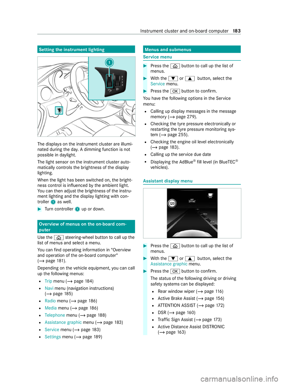
the instrument lighting The displa
yson the instrument clus ter are illumi‐
nated during the da y.A dimming function is not
possible in da ylight.
The light sensor on the instrument clus ter auto‐
matically controls the brightness of the display
lighting.
When the light has been switched on, the bright‐
ness contro l is influenced bythe ambient light.
Yo u can then adjust the brightness of the instru‐
ment lighting and the display lighting with con‐
troller 1aswell. #
Turn controller 1up or down. Overview of menus on the on-board com‐
puter
Use the00E2 steering-wheel button tocall up the
list of menus and select a menu.
Yo u can find ope rating information in "O verview
and operation of the on-board computer"
(/ page 181).
Depending on theve hicle equipment, you can call
up thefo llowing menus:
R Trip menu (/ page184)
R Navi menu (navigation instructions)
(/ page 185)
R Radio menu (/ page 186)
R Media menu (/ page186)
R Telepho nemenu (/ page 188)
R Assistance graphic menu (/page 183)
R Service menu (/ page183)
R Settings menu (/ page189) Menus and submenus
Service menu
#
Press the00E2 button tocall up the list of
menus. #
With th e0064 or0063 button, select the
Service menu. #
Press the0076 button toconfirm.
Yo u ha vethefo llowing options in the Service
menu:
R Calling up display messages in the message
memory (/ page279).
R Che cking the tyre pressure electronically or
re starting the tyre pressure monitoring sys‐
te m (/ page 255).
R Checking the engine oil le vel elect ronically
(/ page 183).
R Calling up the service due date
R Displaying theAd Blue ®
fill le vel (in BlueTEC ®
ve hicles). Assistant display menu
#
Press the00E2 button tocall up the list of
menus. #
With th e0064 or0063 button, select the
Assistance graphic menu. #
Press the0076 button toconfirm.
The status of thefo llowing driving or driving
saf ety sy stems can be displa yed:
R Rear wind owwiper (/ page116)
R Active Brake Assi st (/ page 156)
R ATTENTION ASSIST (/ page172)
R DSR (/ page 160)
R Traf fic Sign Assi st (/ page 173)
R Active Dis tance Assi stDISTRONIC
(/ page 163) Instrument clus
ter and on-board computer 18 3
Page 199 of 337
#
Toenter characters with theke yboard: tap
on a button. #
Touse handwriting toenter characters:
write thech aracter with one finger on the
to uchsc reen. #
Tozoom in and out of the map: movetwo
fi ngers toget her or apart. #
Toenlar georreduce the size of a section
of a website: movetwo fingers toget her or
apart. #
Tocall up a global menu in the applica‐
tions: touch theto uchsc reen and hold until
th eOPTIONS menu appears.
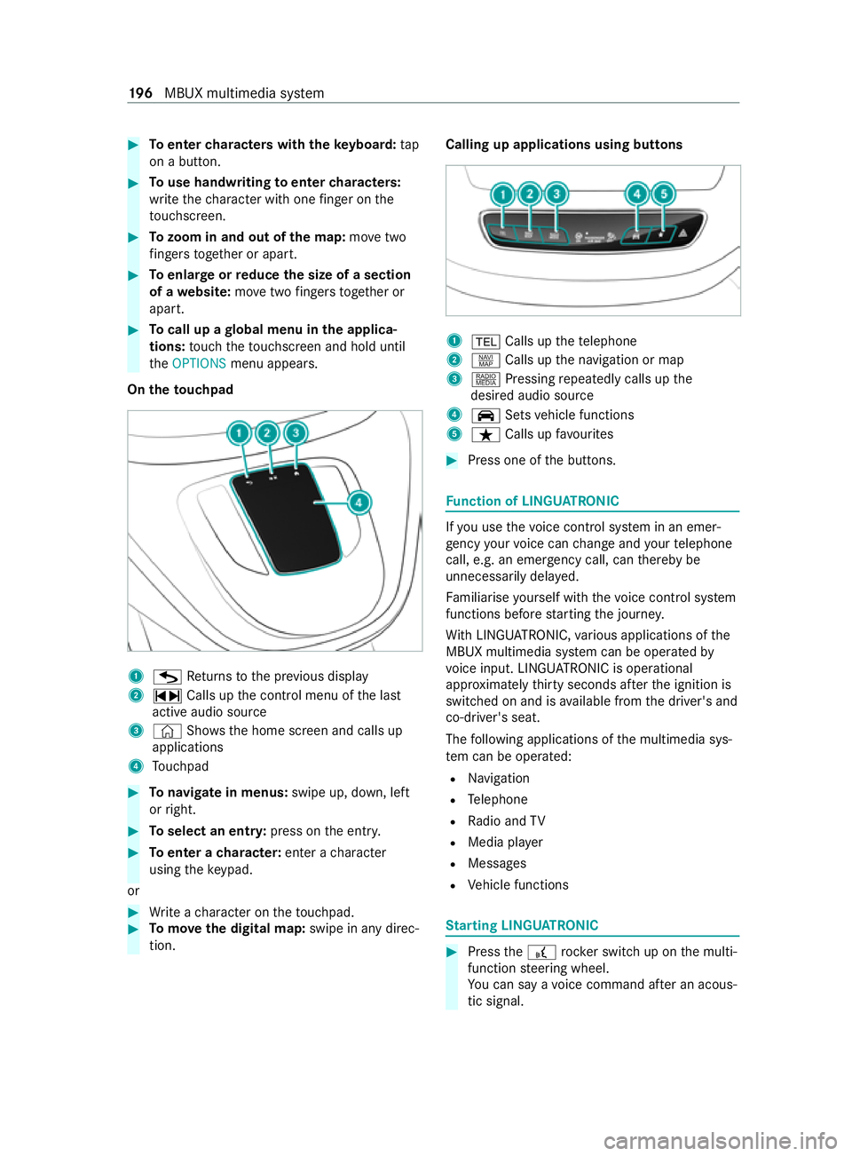
On theto uchpad 1
G Returns tothe pr evious display
2 ~ Calls up the cont rol menu of the last
active audio source
3 © Shows th e home screen and calls up
applications
4 Touchpad #
Tonavigate in menus: swipe up, down, left
or right. #
Toselect an entr y:press on the entry. #
Toenter a character: enter acharacter
using theke ypad.
or #
Write a character on theto uchpad. #
Tomo vethe digital map: swipe in any direc‐
tion. Calling up applications using butto
ns 1
002B Calls up thete lephone
2 z Calls up the navigation or map
3 | Pressing repeatedly calls up the
desired audio source
4 00CE Setsvehicle functions
5 ß Calls up favo urites #
Press one of the buttons. Fu
nction of LINGU ATRO NIC If
yo u use thevo ice control sy stem in an emer‐
ge ncy your voice can change and your telephone
call, e.g. an emer gency call, can thereby be
unnecessarily dela yed.
Fa miliarise yourself with thevo ice control sy stem
functions before starting the journe y.
Wi th LINGU ATRO NIC, various applications of the
MBUX multimedia sy stem can be operated by
vo ice input. LINGU ATRO NIC is operational
appr oximately thirty seconds af terth e ignition is
switched on and is available from the driver's and
co-driver's seat.
The following applications of the multimedia sys‐
te m can be operated:
R Navigation
R Telephone
R Radio and TV
R Media pla yer
R Messages
R Vehicle functions St
arting LING UATRONIC #
Press the£ rocker switch up on the multi‐
function steering wheel.
Yo u can say a voice command af ter an acous‐
tic signal. 19 6
MBUX multimedia sy stem
Page 215 of 337

Note
s on loading guidelines &
DANG ER Risk of exhaust gas poisoning
Combustion engines emit poisonous exhaust
ga ses such as carbon monoxide. Exhaust
ga ses can enter theve hicle interior if theta il‐
gate is open when the engine is running,
especially if theve hicle is in motion. #
Always switch off the engine before
opening theta ilgate. #
Never drive with theta ilgate open. &
WARNING Risk of injury from unsecured
objects in theve hicle
When objects are unsecured or inadequately
secured, they can slip, tip over or be thro wn
about, striking vehicle occupants.
This also applies to:
R luggage or loads
R seats which ha vebeen remo ved and are
being transpor ted in theve hicle in an
exc eptional case
There is a risk of injur y,particularly in the
ev ent of braking manoeuvres or abrupt
ch anges in direction. #
Alwaysstow objects in such a wayth at
th ey cannot be tossed about. #
Before tr avelling, secure objects, lug‐
ga ge or load topreve ntthem slipping or
tipping over. #
When a seat is remo ved, keep it prefera‐
bly outside theve hicle. &
WARNING Risk of accident due toincor‐
re ctly positioned load
The centre of gr avity of the load can be too
high and/or toofa rto wa rdsth ere ar.
This can significantly impair handling as well
as steering and braking characteristics. #
Always make sure that the cent reof
gr av ity of the load is between the axles
and as low as possible near there ar
axle. &
WARNING Risk of accident due to
exc eeding the permissible wheel/axle
loads or the gross vehicle weight
The driving characteristics, as well as steering
and braking, may be greatly impaired. Over‐
loaded tyres may overheat and bur stas a
consequence. #
When transpo rting a load, alw ays
obser vethe permissible wheel loads,
axle loads and the maximum permissi‐
ble gross mass forth eve hicle (including
occupants). &
WARNING Risk of injury if unsuitable
climbing aids are used
In theev ent that you use openings in the
bodywork or attachments as steps, you
could:
R Slip and/or fall.
R Damage theve hicle and thus slip and fall. #
Always use non-slip, stable climbing
aids, e.g. a suitable ladder. *
NO
TEDama gecaused bythe use of
openings in the bodywork or de tach able
part as a step Using
the lo wer guide of the sliding door (car‐
ri age) as a step can damage the trim and/or
mechanism of the sliding door. #
Do not use the guide of the sliding door
(car riage) as a step. If
yo u are using a roof luggage rack , please no te
th e maximum roof load and the maximum load
capacity of thero of luggage rack ( /page 278).
The handling characteristics of your vehicle are
dependent on the load distribution.
Therefore, please obser vethefo llowing no tes
when loading:
R the load must not pr otru de abo vethe upper
edge of the seat backrests.
R if possible, alw ays transport the load in the
load compartment.
R fastenthe load tothe tie-down eyes and dis‐
tribute the load evenly among them. 212
Transporting
Page 222 of 337

Fi
tting the lug gage compa rtment partition If possible,
fit luggage compa rtment partition 1
with the help of ano ther person. #
Place luggage compartment partition 1into
th eve hicle at an angle. #
Rotate luggage compartment partition 1in
th eve hicle and insert it into the guide rails.
The guide rails ha vetriangular ma rkings at the
place tobe inser ted which must be at the same
height as le vers 2 . #
Swing le vers 2 outwards.
Lu ggage compartment partition 1is loc ked. #
Fold luggage compartment partition 1
down. Car
rier sy stems Note
s on car rier sy stems &
WARNING Risk of accident due to
exc eeding the maximum roof load
The vehicle centre of gravity and the usual
driving characteristics as well as thesteering
and braking characteristics alter.
If yo uexc eed the maximum roof load, the
driving characteristics, as well as steering and
braking, will be greatly impaired. #
Neverexc eed the maximum roof load
and adjust your driving style. Yo
u can find information on the maximum roof
load under "Lashing points and car rier sy stems"
(/ page 278). *
NO
TEDama gedue toexc eeding the
maximum permissible roof load If
th ewe ight of thero of luggage, including the
ro of luggage rack ,exc eeds the maximum per‐
missible roof load, this can cause damage to
th eve hicle. #
Do not exceed the maximum permissi‐
ble roof load. #
Arrange the supporting feet of thero of
luggage rack at an even di stance from
each other. #
Installth e basic car rier bars forra il in
front of and behind the mid-section sup‐
port. *
NO
TEDama getotheth re aded holes of
th ero of luggage rack due toan exces‐
sively high tigh tening torque An
exc essively high tightening torque or an
insu fficient scr ew-in dep thcan cause damage
to theth re ad of thero of luggage rack 'sthre a‐
ded holes. #
Tighten the scr ewsto a maximum tor‐
qu e of 10Nm. #
Comply with the minimum scr ewpene‐
tration of four revo lutions in theth re ad.
Use roof and rear luggage rack sth at ha ve
been appr oved or recommended for
Mercedes-Benz. These help topreve ntvehicle
damage. Yo
u can ins tall a roof luggage rack on thero of
and, forex ample, a rear bicycle rack on theta il‐
ga te.
Ins tallth e co ver caps of the securing thre ad af ter
re moving thero of luggage rack.
If yo u ha veinstalled a rear luggage rack on the
ta ilgate, the additional weight restricts the assis‐
ta nce of fere dby the pneumatic springs when you
open theta ilgate. You will then need more force
to open theta ilgate. Atlow outside temp eratures
below freezing point, you should pr ovide addi‐
tional support forth eta ilgate af ter opening it in
order topreve nt it from lo wering unintentionally. Tr
ansporting 219
Page 237 of 337

The Mercedes-Benz emer
gency call centre
can transmit theve hicle position data toone
of the public emer gency services call centres.
R Under cer tain circums tances da tais also
transmitte d inthevo ice channel tothe
Mercedes-Benz emergency call centre.
This allo wsmeasu resfo rre scue, reco very or
to wing toa Mercedes-Benz Service Cent reto
be initiated quickl y.
The SOS button in theove rhead cont rol panel
fl ashes until the emer gency call is finished.
It is not possible toimmediately end an auto‐
matic emer gency call.
If th e Mercedes-Benz emer gency call sy stem can‐
not connect tothe Mercedes-Benz emer gency
call centre, the emer gency call is au tomatically
sent tothe public emer gency services call centre.
If no connection can be made tothe public emer‐
ge ncy services, a cor responding message
appears inthe displa y. #
Dial the emer gency number 11 2onyour
mobile phone.
If an emer gency call has been initia ted:
R Remain in theve hicle if thero ad and traf fic
conditions permit youto do so until a voice
connection is es tablished with the emer gency
call centre ope rator.
R Based on the call, the operator decides
whe ther it is necessary tocall rescue teams
and/or the police tothe accident site.
R If no vehicle occupant answers, an ambu‐
lance is sent totheve hicle immediately. Tr
iggering a manual Mercedes-Benz emer‐
ge ncy call #
Touse the SOS but ton in theove rhead
control panel: pressthe SOS button at least
one second long. #
Touse voice control: usethe LINGUA‐
TRONIC Call the Mercedes accident centre
vo ice command .
When the emer gency call is made:
R Avo ice connection is made tothe Mercedes-
Benz emer gency call centre.
R A messa gewith accident data is transmit ted
to the Mercedes-Benz emer gency call centre. The Mercedes-Benz eme
rgency call centre
can transmit theve hicle position data toone
of the public emer gency services call centres.
R Remain in theve hicle if thero ad and traf fic
conditions permit youto do so until a voice
connection is es tablished with the emer gency
call centre ope rato r.
R Based on the call, the operator decides
whe ther it is necessary tocall rescue teams
and/or the police tothe accident site.
R Under cer tain circums tances da tais also
transmitte d inthevo ice channel tothe
Mercedes-Benz emergency call centre.
This allo wsmeasu resfo rre scue, reco very or
to wing toa Mercedes-Benz Service Cent reto
be initiated quickl y.
If th e Mercedes-Benz emer gency call sy stem can‐
not connect tothe Mercedes-Benz emer gency
call centre, the emer gency call is au tomatically
sent tothe public emer gency services call centre.
If no connection can be made tothe public emer‐
ge ncy services, a cor responding message
appears inthe media displa y. #
Dial the emer gency number 11 2onyour
mobile phone.
Ending an unin tentional Mercedes-Benz emer‐
ge ncy call #
Select 0076onthe multifunction steering
wheel. Tr
ansmitted data Mercedes-Benz with the
Mercedes-Benz emer gency call In
theeve nt of an auto matic or manual emer‐
ge ncy call, as well as for a 11 2 emer gency call,
da ta is transmitte dto the Mercedes-Benz emer‐
ge ncy call centre or the public emer gency serv‐
ices call centre.
The following data is transmitte d:
R Vehicle's GPS position data
R GPS position data on thero ute (a few hun‐
dred metres before the incident)
R Direction of tra vel
R Vehicle identification number
R Vehicle drive type
R The estimated number of people in theve hi‐
cle
R Whe ther the emer gency call was initiated
manually or automatically 234
Breakdown assis tance
Page 238 of 337

R
Time of the accident
R Language setting on the multimedia sy stem
Fo r accident clarification purposes, thefo llowing
measures can be take n up toan hour af terthe
emer gency call has been initia ted:
R The cur rent vehicle position can be called up
R Avo ice connection totheve hicle occupants
can be es tablished
% Fo
rRu ssia: various functions, e.g. receiving
traf fic information, cannot be used for up to
two hou rsafte r sending an emergency call. Fu
nction of the emer gency call sy stem self-
diagnosis (Russia) Yo
ur car verifies the operability of the emer gency
call sy stem each time the ignition is ON.
In theeve nt of a sy stem malfunction, you will be
informed bythefo llowing signals:
R The SOS NOT READY message inthe instru‐
ment clus ter or there dSOS NOT READY mes‐
sage on the displa y,ifav ailable
R The flashing indicator lamp in theove rhead
cont rol panel
Please, make sure, that during 30 seconds af ter
switching ignition ON there d indicator SOS NOT
READY inthe upper right corner of the multime‐
dia display is switched OFF, this means the emer‐
ge ncy call sy stem passed diagnostics success‐
fully. St
arting/ending ERA-GLONASS test mode
(Russia) Re
quirements:
R The star ter battery has suf ficient charge.
R The ignition is switched on.
R The vehicle has been stationary for at least
one minute. #
Tostart thete st mode: press and hold the
0076 button on the multifunction steering
wheel or the0052 button on theove rhead
cont rol panel for at least five seconds.
Te st mode is star ted and ended automatically
af te r completion of the speech test. #
Tosto pte st mode manuall y:switch off the
ignition or press the0052 button on theov er‐
head contro l panelfor at least five seconds.
The test mode is ended. Flat tyre
Note
s onflat tyres &
WARNING Risk of accident due toaflat
tyre
A flat tyre strongly impairs theve hicle's driv‐
ing characteristics, as well as its steering and
braking characteristics. #
Do not drive with a flat tyre. #
Replace theflat tyre with the spare
wheel. Alternatively, consult a qualified
specialist workshop. Yo
u will find a sticke r with the Mercedes-Benz
Service24h telephone number on the B-pillar on
th e driver's side, forex ample.
Fo rve hicles with a spare wheel, information in
th eeve nt of a flat tyre can be found under
"Wheels and tyres" (/ page 256). Battery
Note
s onthest ar ter battery Wo
rkon the batter y,e.g. removing or ins talling,
requ ires specialist know ledge andthe use of spe‐
cial tools. Therefore, alw ays ha vewo rkon the
battery car ried out at a qualified specialist work‐
shop. &
WARNING Risk of an accident due to
wo rkcar ried out incor rectly on the bat‐
te ry
Wo rkcar ried out incor rectly on the battery
can, forex ample, lead toa short circuit. This
can restrict functions releva nt for saf ety sys‐
te ms and impair the operating saf ety of your
ve hicle.
Yo u could lose control of theve hicle in the
fo llowing situations in particular:
R when braking
R intheeve nt of ab rupt steering manoeu‐
vres and/or when theve hicle's speed is
not adap tedto thero ad conditions #
Intheeve nt of a sho rtcircuit or a simi‐
lar incident, contact a qualified special‐
ist workshop immediately. #
Do not drive on. #
Always ha vewo rkon the battery car ried
out at a qualified specialist workshop. Breakdown assis
tance 235
Page 245 of 337
#
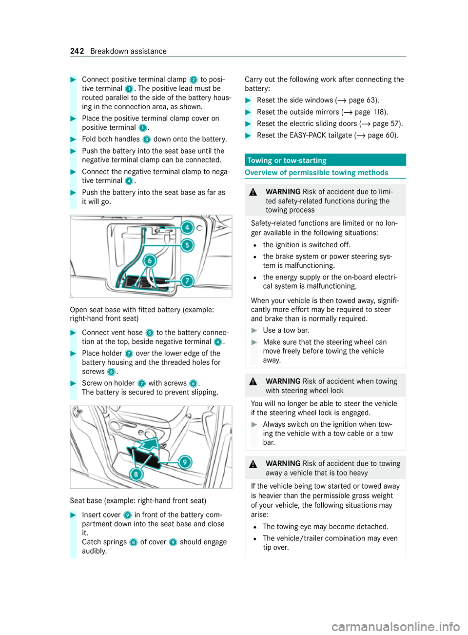
Connect positive term inal clamp 2toposi‐
tive term inal 1. The positive lead must be
ro uted parallel tothe side of the battery hous‐
ing in the connection area, as shown. #
Place the positive term inal clamp co ver on
positive term inal 1. #
Fold bo thhandles 3down onto the batter y. #
Push the battery into the seat base until the
negati ve terminal clamp can be connec ted. #
Connect the negative term inal clamp tonega‐
tive term inal 4. #
Push the battery into the seat base as far as
it will go. Open seat base with
fitted battery (e xamp le:
ri ght-hand front seat) #
Connect vent hose 5tothe battery connec‐
tion at theto p, beside negative term inal 4. #
Place holder 7over the lo wer edge of the
battery housing and theth re aded holes for
scr ews6. #
Screw on holder 7with scr ews6.
The battery is secured topreve nt slipping. Seat base (e
xamp le:right-hand front seat) #
Insert co ver9 in front of the battery com‐
partment down into the seat base and close
it.
Catch springs 8of co ver9 should engage
audibly. Car
ryout thefo llowing workafte r connecting the
battery: #
Reset the side windo ws (/page 63). #
Reset the outside mir rors ( / page 118). #
Reset the electric sliding doors (/ page57). #
Reset the EASY -PAC Ktailgate (/ page 60). To
wing or tow- starting Overview of permissible
towing me thods &
WARNING Risk of accident due tolimi‐
te d saf ety-re lated functions during the
to wing process
Saf ety-re lated functions are limited or no lon‐
ge rav ailable in thefo llowing situations:
R the ignition is switched off.
R the brake sy stem or po werst eering sys‐
te m is malfunctioning.
R the energy supply or the on-board electri‐
cal sy stem is malfunctioning.
When your vehicle is then towe daw ay, signifi‐
cantly more ef fort may be requ ired tosteer
and brake than is normally required. #
Use a tow bar. #
Make sure that thesteering wheel can
mo vefreely before towing theve hicle
aw ay. &
WARNING Risk of accident when towing
with steering wheel lock
Yo u will no lon ger be able tosteer theve hicle
if th esteering wheel lock is engaged. #
Always switch on the ignition when tow‐
ing theve hicle with a tow cable or a tow
bar. &
WARNING Risk of accident due to towing
aw ay ave hicle that is too heavy
If th eve hicle being tow star ted or towe daw ay
is heavier than the permissible gross weight
of your vehicle, thefo llowing situations may
arise:
R The towing eye may become de tach ed.
R The vehicle/trailer combination may even
tip ove r. 242
Breakdown assis tance