tow Mercury Grand Marquis 2002 Owner's Manuals
[x] Cancel search | Manufacturer: MERCURY, Model Year: 2002, Model line: Grand Marquis, Model: Mercury Grand Marquis 2002Pages: 248, PDF Size: 1.81 MB
Page 2 of 248
Seating and Safety Restraints 106
Seating 106
Safety restraints 110
Air bags 125
Child restraints 130
Driving 138
Starting 138
Brakes 142
Traction control/AdvanceTrac 145
Transmission operation 148
Vehicle loading 153
Trailer towing 154
Recreational towing 157
Roadside Emergencies 158
Hazard flasher switch 159
Fuses and relays 161
Changing tires 166
Jump starting 171
Wrecker towing 176
Customer Assistance 177
The dispute settlement board 180
Utilizing the mediation/arbitration 183
Getting assistance outside the U.S. and Canada 183
Ordering additional owner's literature 184
Reporting safety defects (U.S. only) 186
Cleaning 187
Cleaning your vehicle 187
Underbody preservation 192
Table of Contents
2
Page 6 of 248

Protecting the environment
We must all play our part in
protecting the environment. Correct
vehicle usage and the authorized
disposal of waste cleaning and
lubrication materials are significant
steps towards this aim. Information in this respect is highlighted in this
guide with the tree symbol.
BREAKING-IN YOUR VEHICLE
There are no particular guidelines for breaking-in your vehicle. During
the first 1 600 km (1 000 miles) of driving, vary speeds frequently. This is
recommended to give the moving parts a chance to break in.
SPECIAL NOTICES
Emission warranty
The New Vehicle Limited Warranty includes Bumper-to-Bumper
Coverage, Safety Restraint Coverage, Corrosion Coverage, and 7.3L
Power Stroke Diesel Engine Coverage. In addition, your vehicle is eligible
for Emissions Defect and Emissions Performance Warranties. For a
detailed description of what is covered and what is not covered, refer to
theWarranty Guidethat is provided to you along with your Owner's
Guide.
Introduction
6
Page 11 of 248
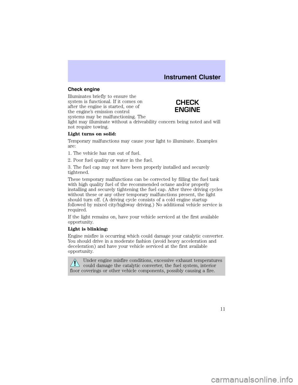
Check engine
Illuminates briefly to ensure the
system is functional. If it comes on
after the engine is started, one of
the engine's emission control
systems may be malfunctioning. The
light may illuminate without a driveability concern being noted and will
not require towing.
Light turns on solid:
Temporary malfunctions may cause your light to illuminate. Examples
are:
1. The vehicle has run out of fuel.
2. Poor fuel quality or water in the fuel.
3. The fuel cap may not have been properly installed and securely
tightened.
These temporary malfunctions can be corrected by filling the fuel tank
with high quality fuel of the recommended octane and/or properly
installing and securely tightening the fuel cap. After three driving cycles
without these or any other temporary malfunctions present, the light
should turn off. (A driving cycle consists of a cold engine startup
followed by mixed city/highway driving.) No additional vehicle service is
required.
If the light remains on, have your vehicle serviced at the first available
opportunity.
Light is blinking:
Engine misfire is occurring which could damage your catalytic converter.
You should drive in a moderate fashion (avoid heavy acceleration and
deceleration) and have your vehicle serviced at the first available
opportunity.
Under engine misfire conditions, excessive exhaust temperatures
could damage the catalytic converter, the fuel system, interior
floor coverings or other vehicle components, possibly causing a fire.
CHECK
ENGINE
Instrument Cluster
11
Page 18 of 248
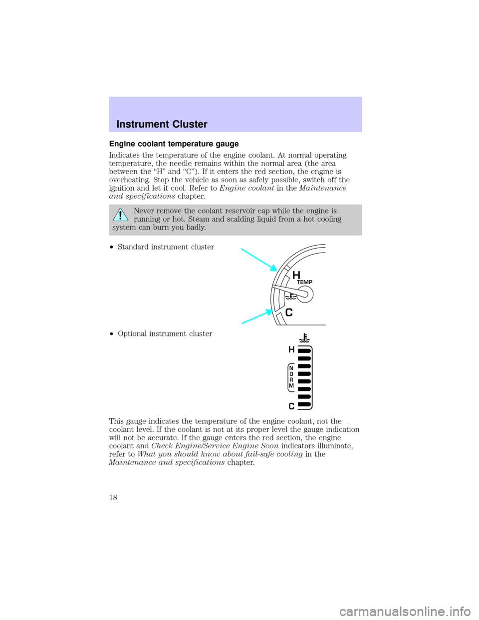
Engine coolant temperature gauge
Indicates the temperature of the engine coolant. At normal operating
temperature, the needle remains within the normal area (the area
between the ªHº and ªCº). If it enters the red section, the engine is
overheating. Stop the vehicle as soon as safely possible, switch off the
ignition and let it cool. Refer toEngine coolantin theMaintenance
and specificationschapter.
Never remove the coolant reservoir cap while the engine is
running or hot. Steam and scalding liquid from a hot cooling
system can burn you badly.
²Standard instrument cluster
²Optional instrument cluster
This gauge indicates the temperature of the engine coolant, not the
coolant level. If the coolant is not at its proper level the gauge indication
will not be accurate. If the gauge enters the red section, the engine
coolant andCheck Engine/Service Engine Soonindicators illuminate,
refer toWhat you should know about fail-safe coolingin the
Maintenance and specificationschapter.
TEMPH
C
N
O
R
M
H
C
Instrument Cluster
18
Page 49 of 248

RADIO RECEPTION FACTORS
Three factors can affect radio reception:
²Distance/strength.The further an FM signal travels, the weaker it is.
The listenable range of the average FM station is approximately 40 km
(24 miles). This range can be affected by ªsignal modulation.º Signal
modulation is a process radio stations use to increase their
strength/volume relative to other stations.
²Terrain.Hills, mountains and tall buildings between your vehicle's
antenna and the radio station signal can cause FM reception problems.
Static can be caused on AM stations by power lines, electric fences,
traffic lights and thunderstorms. Moving away from an interfering
structure (out of its ªshadowº) returns your reception to normal.
²Station overload.Weak signals are sometimes captured by stronger
signals when you pass a broadcast tower. A stronger signal may
temporarily overtake a weaker signal and play while the weak station
frequency is displayed.
The audio system automatically switches to single channel reception if it
will improve the reception of a station normally received in stereo.
AUDIO SYSTEM WARRANTIES AND SERVICE
Refer to theWarranty Guidefor audio system warranty information.
If service is necessary, see your dealer or a qualified technician.
Entertainment Systems
49
Page 52 of 248
²Under normal weather conditions, your vehicle's climate control
system should be left in any position other than the MAX A/C or OFF
when the vehicle is parked. This allows the vehicle to ªbreatheº
through the outside air inlet duct.
²Under snowy or dirty weather conditions, your vehicle's climate
control system should be left in the OFF position when the vehicle is
parked. This allows the climate control system to be free from
contamination of outside pollutants.
²If your vehicle has been parked with the windows closed during warm
weather conditions, the air conditioner will perform more efficiently in
cooling the vehicle if driven for two or three minutes with the
windows open. This will force most of the hot, stale air out of the
vehicle. Once the vehicle has been ªaired outº, operate the climate
control system as desired.
²Do not put objects under the front seat which may interfere with the
airflow to the rear seats (if equipped).
²Remove any snow, ice or leaves from the air intake area (at the
bottom of the windshield and underneath the hood).
²Do not place objects over the defroster outlets. These objects can
block airflow and reduce visibility through your windshield. Avoid
placing small objects on top of the instrument panel. These objects
may fall down into the defroster outlets and block airflow, in addition
to, damaging the climate control system.
To aid in side window defogging/demisting in cold weather conditions:
1. Select the position that distributes air through the Panel and Floor.
2. Set the temperature control to full heat.
3. Set the fan speed to full fan.
4. Direct the outer panel vents towards the side windows.
5. To increase airflow to the outer panel vents, close the central panel
vents.
Do not place objects on top of the instrument panel as these
objects may become projectiles in a collision or sudden stop.
Climate Controls
52
Page 58 of 248
²Don't put objects under the front seat that will interfere with the
airflow to the rear seats.
²Remove any snow, ice or leaves from the air intake area at the area at
the base of the windshield.
²Do not place objects over the defroster outlets. These objects can
block airflow and reduce your ability to see through your windshield.
Avoid placing small objects on top of the instrument panel. These
objects may fall down into the defroster outlets and block airflow, in
addition to damaging the climate control system.
To aid in side window defogging/demisting in cold weather conditions:
1. Select VENT
2. Set the temperature control to full heat
3. Set the fan speed to HI
4. Direct the outer panel vents towards to side windows
To increase airflow to the outer panel vents, close the central panel
vents.
Do not place objects on top of the instrument panel, as these
objects may become projectiles in a collision or sudden stop.
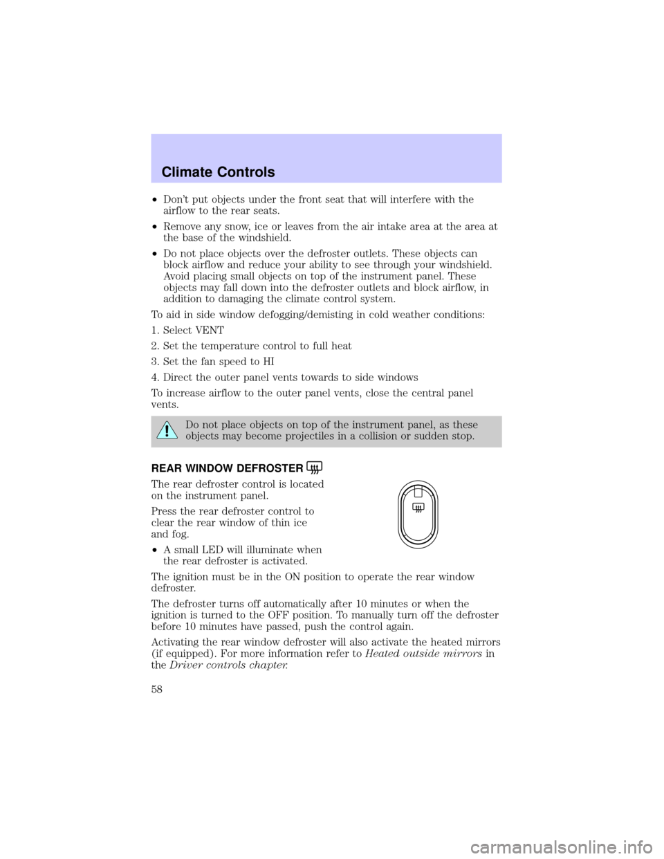
REAR WINDOW DEFROSTER
The rear defroster control is located
on the instrument panel.
Press the rear defroster control to
clear the rear window of thin ice
and fog.
²A small LED will illuminate when
the rear defroster is activated.
The ignition must be in the ON position to operate the rear window
defroster.
The defroster turns off automatically after 10 minutes or when the
ignition is turned to the OFF position. To manually turn off the defroster
before 10 minutes have passed, push the control again.
Activating the rear window defroster will also activate the heated mirrors
(if equipped). For more information refer toHeated outside mirrorsin
theDriver controls chapter.
Climate Controls
58
Page 60 of 248
Daytime running lamps (DRL) (if equipped)
Turns the highbeam headlamps on with a reduced output. To activate:
²the key must be in the ON position,
²the parking brake released, and
²the headlamp control is in the OFF or Parking lamps position
Always remember to turn on your headlamps at dusk or during
inclement weather. The Daytime Running Light (DRL) System
does not activate your tail lamps and generally may not provide
adequate lighting during these conditions. Failure to activate your
headlamps under these conditions may result in a collision.
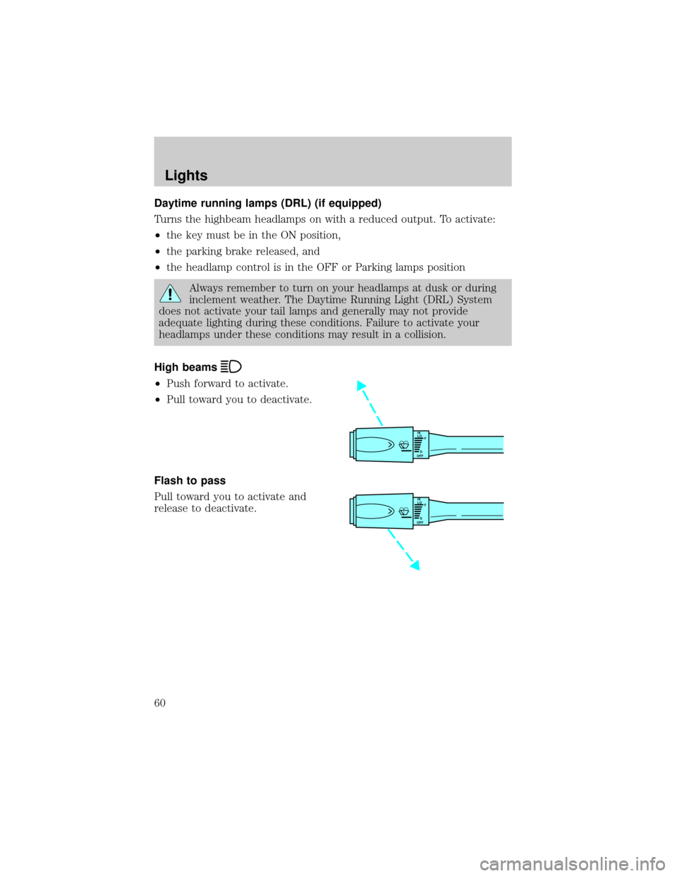
High beams
²Push forward to activate.
²Pull toward you to deactivate.
Flash to pass
Pull toward you to activate and
release to deactivate.
HI
LO
F
S
OFF
HI
LO
F
S
OFF
Lights
60
Page 69 of 248
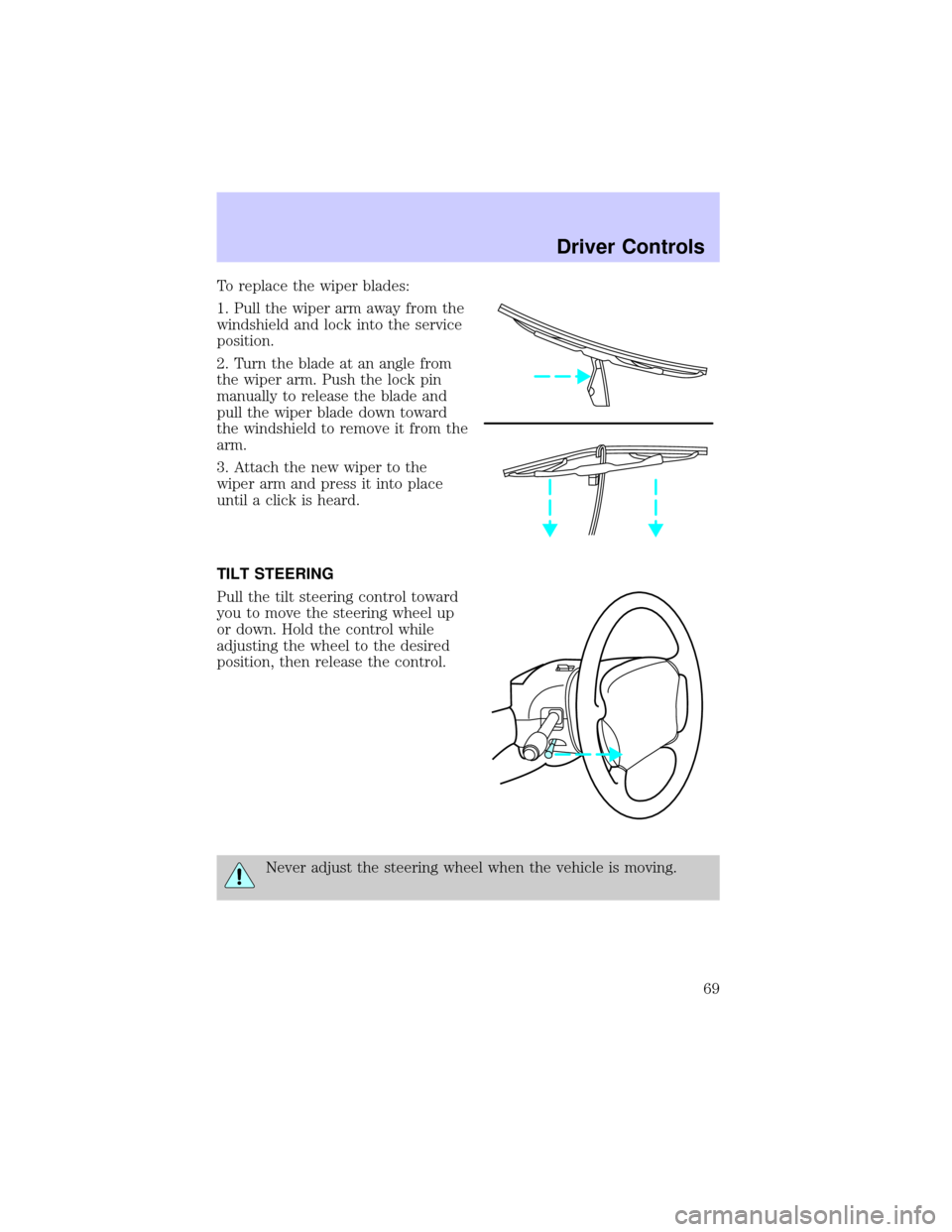
To replace the wiper blades:
1. Pull the wiper arm away from the
windshield and lock into the service
position.
2. Turn the blade at an angle from
the wiper arm. Push the lock pin
manually to release the blade and
pull the wiper blade down toward
the windshield to remove it from the
arm.
3. Attach the new wiper to the
wiper arm and press it into place
until a click is heard.
TILT STEERING
Pull the tilt steering control toward
you to move the steering wheel up
or down. Hold the control while
adjusting the wheel to the desired
position, then release the control.
Never adjust the steering wheel when the vehicle is moving.
Driver Controls
69
Page 74 of 248
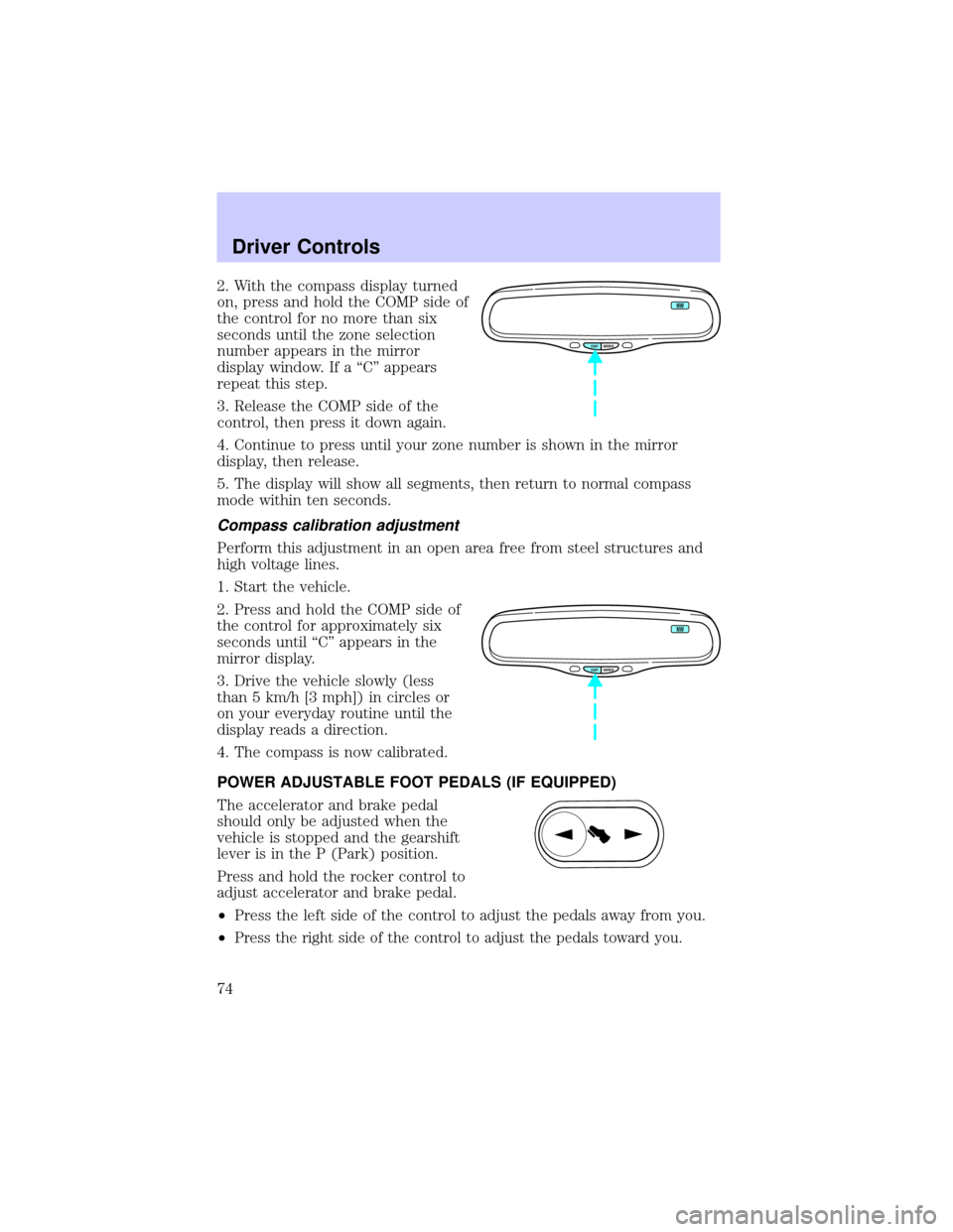
2. With the compass display turned
on, press and hold the COMP side of
the control for no more than six
seconds until the zone selection
number appears in the mirror
display window. If a ªCº appears
repeat this step.
3. Release the COMP side of the
control, then press it down again.
4. Continue to press until your zone number is shown in the mirror
display, then release.
5. The display will show all segments, then return to normal compass
mode within ten seconds.
Compass calibration adjustment
Perform this adjustment in an open area free from steel structures and
high voltage lines.
1. Start the vehicle.
2. Press and hold the COMP side of
the control for approximately six
seconds until ªCº appears in the
mirror display.
3. Drive the vehicle slowly (less
than 5 km/h [3 mph]) in circles or
on your everyday routine until the
display reads a direction.
4. The compass is now calibrated.
POWER ADJUSTABLE FOOT PEDALS (IF EQUIPPED)
The accelerator and brake pedal
should only be adjusted when the
vehicle is stopped and the gearshift
lever is in the P (Park) position.
Press and hold the rocker control to
adjust accelerator and brake pedal.
²Press the left side of the control to adjust the pedals away from you.
²
Press the right side of the control to adjust the pedals toward you.
COMP MIRROR
NW
COMP MIRROR
NW
Driver Controls
74