light Mercury Marauder 2003 s Owner's Guide
[x] Cancel search | Manufacturer: MERCURY, Model Year: 2003, Model line: Marauder, Model: Mercury Marauder 2003Pages: 232, PDF Size: 2.29 MB
Page 46 of 232
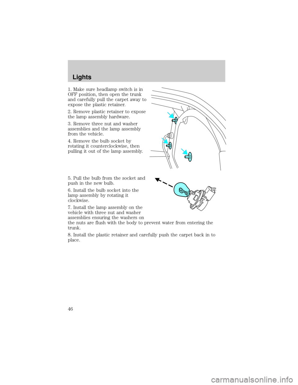
1. Make sure headlamp switch is in
OFF position, then open the trunk
and carefully pull the carpet away to
expose the plastic retainer.
2. Remove plastic retainer to expose
the lamp assembly hardware.
3. Remove three nut and washer
assemblies and the lamp assembly
from the vehicle.
4. Remove the bulb socket by
rotating it counterclockwise, then
pulling it out of the lamp assembly.
5. Pull the bulb from the socket and
push in the new bulb.
6. Install the bulb socket into the
lamp assembly by rotating it
clockwise.
7. Install the lamp assembly on the
vehicle with three nut and washer
assemblies ensuring the washers on
the nuts are flush with the body to prevent water from entering the
trunk.
8. Install the plastic retainer and carefully push the carpet back in to
place.
Lights
46
Page 47 of 232
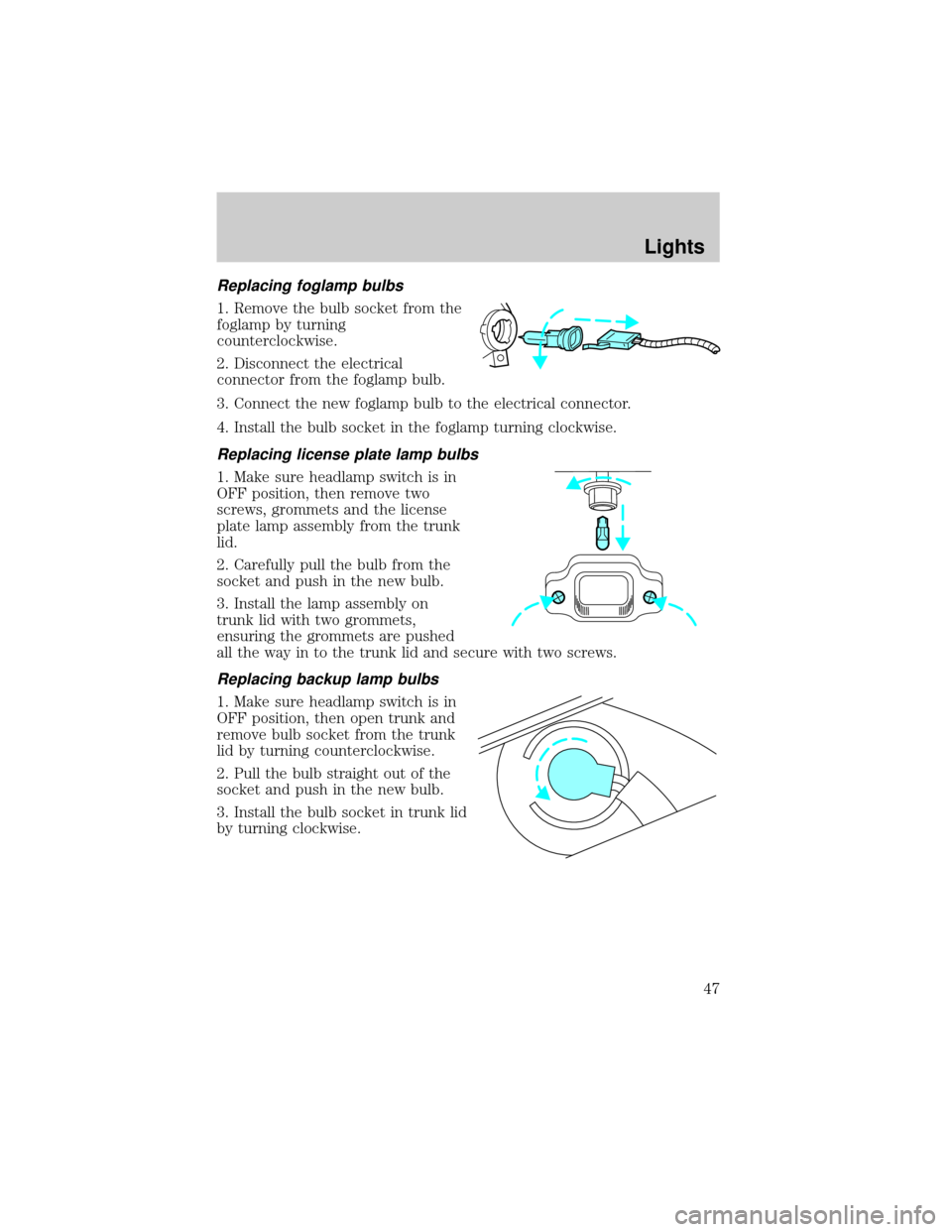
Replacing foglamp bulbs
1. Remove the bulb socket from the
foglamp by turning
counterclockwise.
2. Disconnect the electrical
connector from the foglamp bulb.
3. Connect the new foglamp bulb to the electrical connector.
4. Install the bulb socket in the foglamp turning clockwise.
Replacing license plate lamp bulbs
1. Make sure headlamp switch is in
OFF position, then remove two
screws, grommets and the license
plate lamp assembly from the trunk
lid.
2. Carefully pull the bulb from the
socket and push in the new bulb.
3. Install the lamp assembly on
trunk lid with two grommets,
ensuring the grommets are pushed
all the way in to the trunk lid and secure with two screws.
Replacing backup lamp bulbs
1. Make sure headlamp switch is in
OFF position, then open trunk and
remove bulb socket from the trunk
lid by turning counterclockwise.
2. Pull the bulb straight out of the
socket and push in the new bulb.
3. Install the bulb socket in trunk lid
by turning clockwise.
Lights
47
Page 48 of 232
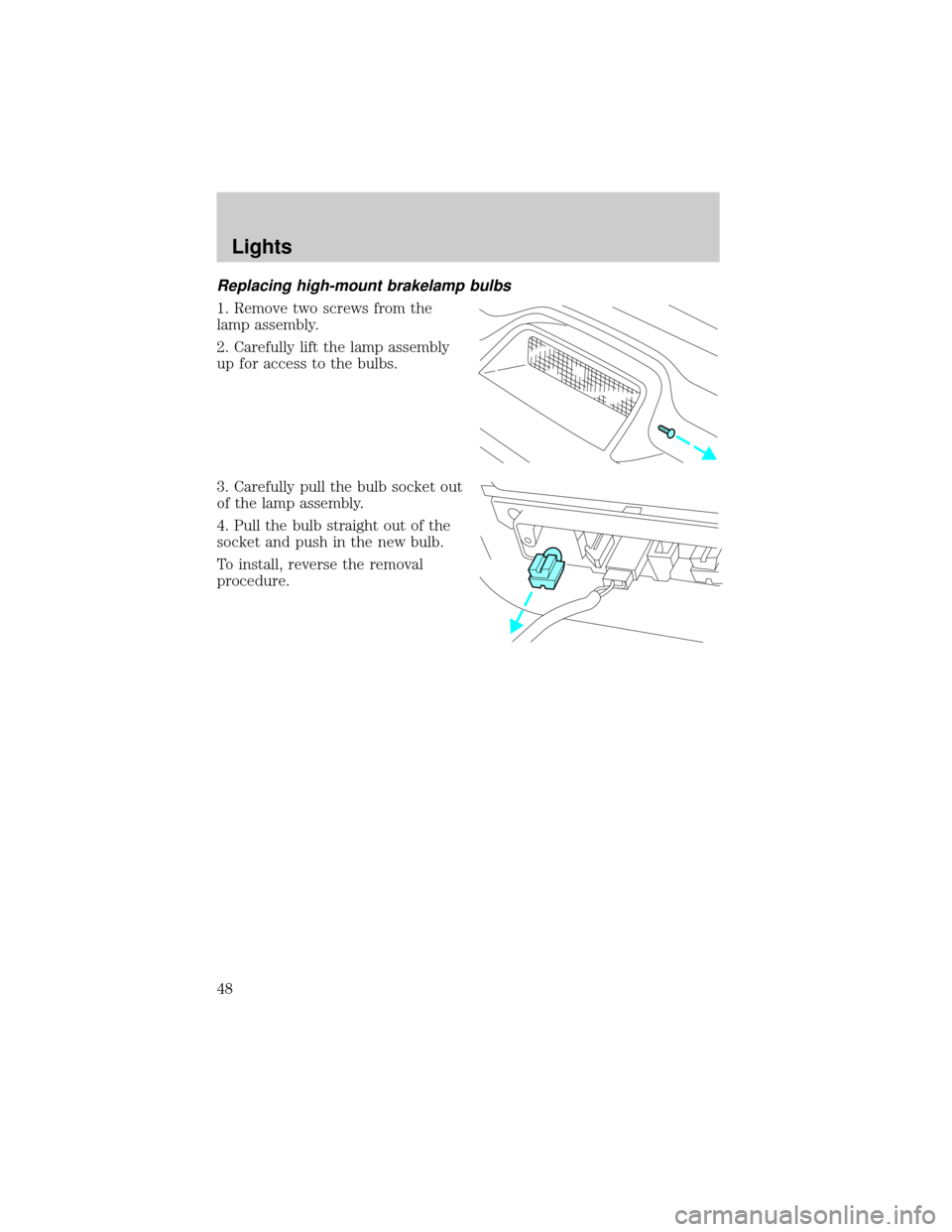
Replacing high-mount brakelamp bulbs
1. Remove two screws from the
lamp assembly.
2. Carefully lift the lamp assembly
up for access to the bulbs.
3. Carefully pull the bulb socket out
of the lamp assembly.
4. Pull the bulb straight out of the
socket and push in the new bulb.
To install, reverse the removal
procedure.
Lights
48
Page 49 of 232
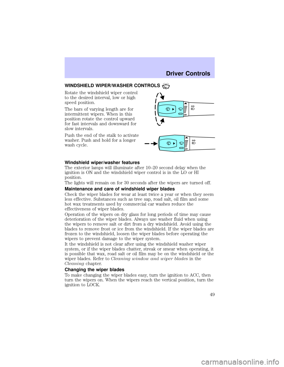
WINDSHIELD WIPER/WASHER CONTROLS
Rotate the windshield wiper control
to the desired interval, low or high
speed position.
The bars of varying length are for
intermittent wipers. When in this
position rotate the control upward
for fast intervals and downward for
slow intervals.
Push the end of the stalk to activate
washer. Push and hold for a longer
wash cycle.
Windshield wiper/washer features
The exterior lamps will illuminate after 10±20 second delay when the
ignition is ON and the windshield wiper control is in the LO or HI
position.
The lights will remain on for 30 seconds after the wipers are turned off.
Maintenance and care of windshield wiper blades
Check the wiper blades for wear at least twice a year or when they seem
less effective. Substances such as tree sap, road salt, oil film and some
hot wax treatments used by commercial car washes reduce the
effectiveness of wiper blades.
Operation of the wipers on dry glass for long periods of time may cause
deterioration of the wiper blades. Always use washer fluid when using
the wipers to remove salt or dirt from a dry windshield. Avoid using the
blades to remove frost or ice from the windshield. If the wiper blades are
frozen to the windshield, loosen the wiper blades before operating the
wipers to prevent damage to the wiper system.
It the windshield is not clear after using the windshield washer wiper
system, or if the wiper blades chatter, streak or smear when operating, it
is possible that wax, road salt or oil film may be on the windshield or the
wiper blades. Refer toCleaning window and wiper bladesin the
Cleaningchapter.
Changing the wiper blades
To make changing the wiper blades easy, turn the ignition to ACC, then
turn the wipers on. When the wipers reach the vertical position, turn the
ignition to LOCK.
Driver Controls
49
Page 51 of 232
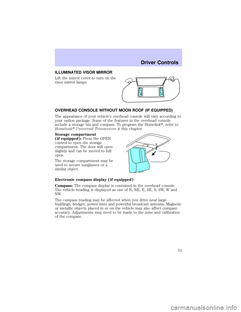
ILLUMINATED VISOR MIRROR
Lift the mirror cover to turn on the
visor mirror lamps.
OVERHEAD CONSOLE WITHOUT MOON ROOF (IF EQUIPPED)
The appearance of your vehicle's overhead console will vary according to
your option package. Some of the features in the overhead console
include a storage bin and compass. To program the Homelinkt, refer to
HomelinktUniversal Transceiverit this chapter.
Storage compartment
(if equipped):Press the OPEN
control to open the storage
compartment. The door will open
slightly and can be moved to full
open.
The storage compartment may be
used to secure sunglasses or a
similar object.
Electronic compass display (if equipped)
Compass:The compass display is contained in the overhead console.
The vehicle heading is displayed as one of N, NE, E, SE, S, SW, W and
NW.
The compass reading may be affected when you drive near large
buildings, bridges, power lines and powerful broadcast antenna. Magnetic
or metallic objects placed in or on the vehicle may also affect compass
accuracy. Adjustments may need to be made to the zone and calibration
of the compass.
Driver Controls
51
Page 53 of 232
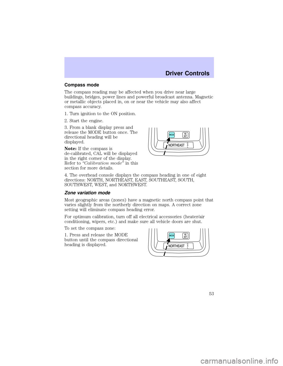
Compass mode
The compass reading may be affected when you drive near large
buildings, bridges, power lines and powerful broadcast antenna. Magnetic
or metallic objects placed in, on or near the vehicle may also affect
compass accuracy.
1. Turn ignition to the ON position.
2. Start the engine.
3. From a blank display press and
release the MODE button once. The
directional heading will be
displayed.
Note:If the compass is
de-calibrated, CAL will be displayed
in the right corner of the display.
Refer toªCalibration modeºin this
section for more details.
4. The overhead console displays the compass heading in one of eight
directions: NORTH, NORTHEAST, EAST, SOUTHEAST, SOUTH,
SOUTHWEST, WEST, and NORTHWEST.
Zone variation mode
Most geographic areas (zones) have a magnetic north compass point that
varies slightly from the northerly direction on maps. A correct zone
setting will eliminate compass heading error.
For optimum calibration, turn off all electrical accessories (heater/air
conditioning, wipers, etc.) and make sure all vehicle doors are shut.
To set the compass zone:
1. Press and release the MODE
button until the compass directional
heading is displayed.
Driver Controls
53
Page 58 of 232
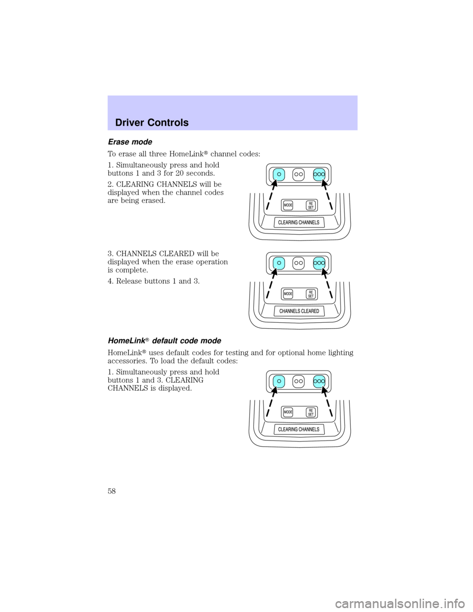
Erase mode
To erase all three HomeLinktchannel codes:
1. Simultaneously press and hold
buttons 1 and 3 for 20 seconds.
2. CLEARING CHANNELS will be
displayed when the channel codes
are being erased.
3. CHANNELS CLEARED will be
displayed when the erase operation
is complete.
4. Release buttons 1 and 3.
HomeLinkTdefault code mode
HomeLinktuses default codes for testing and for optional home lighting
accessories. To load the default codes:
1. Simultaneously press and hold
buttons 1 and 3. CLEARING
CHANNELS is displayed.
Driver Controls
58
Page 59 of 232
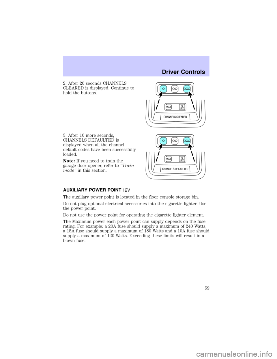
2. After 20 seconds CHANNELS
CLEARED is displayed. Continue to
hold the buttons.
3. After 10 more seconds,
CHANNELS DEFAULTED is
displayed when all the channel
default codes have been successfully
loaded.
Note:If you need to train the
garage door opener, refer toªTrain
modeºin this section.
AUXILIARY POWER POINT
The auxiliary power point is located in the floor console storage bin.
Do not plug optional electrical accessories into the cigarette lighter. Use
the power point.
Do not use the power point for operating the cigarette lighter element.
The Maximum power each power point can supply depends on the fuse
rating. For example: a 20A fuse should supply a maximum of 240 Watts,
a 15A fuse should supply a maximum of 180 Watts and a 10A fuse should
supply a maximum of 120 Watts. Exceeding these limits will result in a
blown fuse.
Driver Controls
59
Page 62 of 232
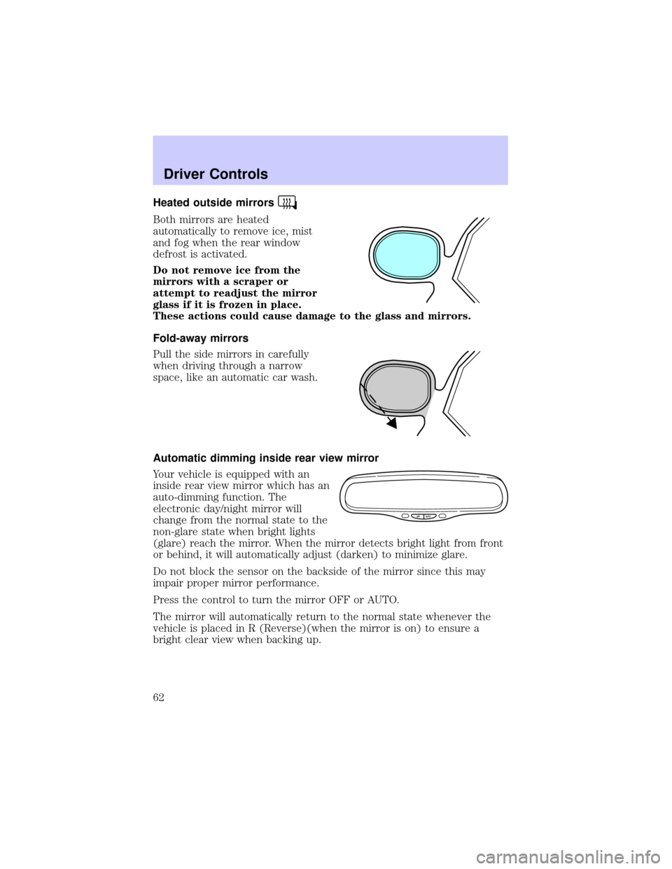
Heated outside mirrors
Both mirrors are heated
automatically to remove ice, mist
and fog when the rear window
defrost is activated.
Do not remove ice from the
mirrors with a scraper or
attempt to readjust the mirror
glass if it is frozen in place.
These actions could cause damage to the glass and mirrors.
Fold-away mirrors
Pull the side mirrors in carefully
when driving through a narrow
space, like an automatic car wash.
Automatic dimming inside rear view mirror
Your vehicle is equipped with an
inside rear view mirror which has an
auto-dimming function. The
electronic day/night mirror will
change from the normal state to the
non-glare state when bright lights
(glare) reach the mirror. When the mirror detects bright light from front
or behind, it will automatically adjust (darken) to minimize glare.
Do not block the sensor on the backside of the mirror since this may
impair proper mirror performance.
Press the control to turn the mirror OFF or AUTO.
The mirror will automatically return to the normal state whenever the
vehicle is placed in R (Reverse)(when the mirror is on) to ensure a
bright clear view when backing up.
OFF AUTO
Driver Controls
62
Page 68 of 232
²To close from the vent position, press and hold the rear portion of the
control.
Do not let children play with the moon roof. They may seriously
hurt themselves.
HOMELINKTUNIVERSAL TRANSCEIVER
The HomeLinktUniversal Transceiver, located on the driver's visor,
provides a convenient way to replace up to three hand-held transmitters
with a single built-in device. This feature will learn the radio frequency
codes of most current transmitters to operate garage doors, entry gate
operators, security systems, entry door locks, and home or office lighting.
When programming your HomeLinktUniversal Transceiver to a
garage door or gate, be sure that people and objects are out of
the way to prevent potential harm or damage.
Do not use the HomeLinktUniversal Transceiver with any garage door
opener that lacks safety stop and reverse features as required by U.S.
federal safety standards (this includes any garage door opener model
manufactured before April 1, 1982). A garage door which cannot detect
an object, signaling the door to stop and reverse, does not meet current
U.S. federal safety standards. For more information, contact HomeLinkt
at:www.homelink.comor1±800±355±3515.
Retain the original transmitter for use in other vehicles as well as for
future programming procedures (i.e. new HomeLinktequipped vehicle
purchase). It is also suggested that upon the sale of the vehicle, the
programmed HomelinktUniversal Transceiver buttons be erased for
security purposes, refer toProgrammingin this section.
Programming
Do not program the HomeLinktUniversal Transceiver with the
vehicle parked in the garage.
Note:Some vehicles may require the ignition switch to be turned to the
second (or ªACCº) position for programming and/or operation of the
HomeLinkt. It is also recommended that a new battery be placed in the
hand-held transmitter of the device being programmed to HomeLinktfor
quicker training and accurate transmission of the radio-frequency signal.
Driver Controls
68