wheel Mercury Marauder 2003 Owner's Manuals
[x] Cancel search | Manufacturer: MERCURY, Model Year: 2003, Model line: Marauder, Model: Mercury Marauder 2003Pages: 232, PDF Size: 2.29 MB
Page 1 of 232
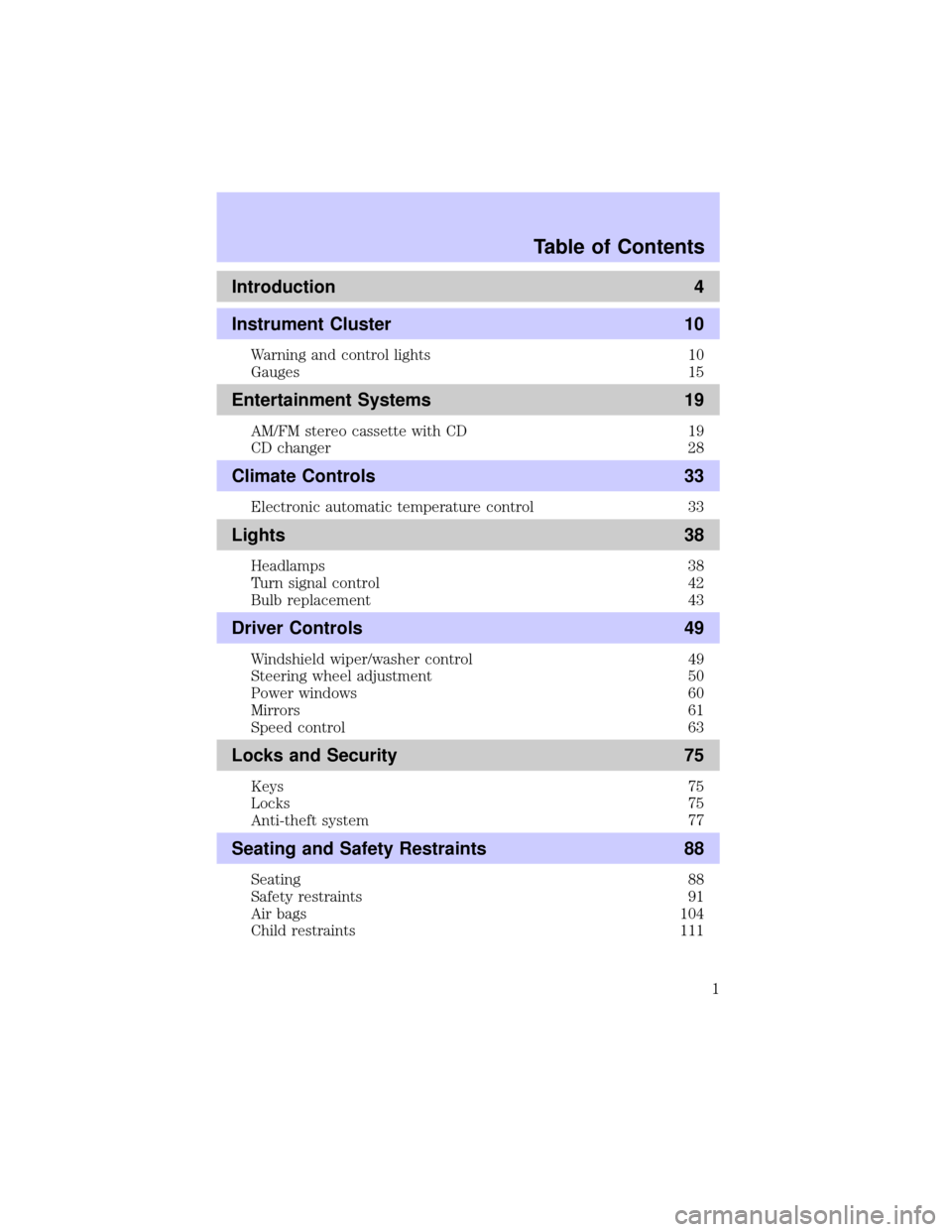
Introduction 4
Instrument Cluster 10
Warning and control lights 10
Gauges 15
Entertainment Systems 19
AM/FM stereo cassette with CD 19
CD changer 28
Climate Controls 33
Electronic automatic temperature control 33
Lights 38
Headlamps 38
Turn signal control 42
Bulb replacement 43
Driver Controls 49
Windshield wiper/washer control 49
Steering wheel adjustment 50
Power windows 60
Mirrors 61
Speed control 63
Locks and Security 75
Keys 75
Locks 75
Anti-theft system 77
Seating and Safety Restraints 88
Seating 88
Safety restraints 91
Air bags 104
Child restraints 111
Table of Contents
1
Page 33 of 232
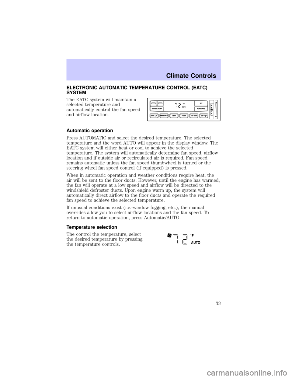
ELECTRONIC AUTOMATIC TEMPERATURE CONTROL (EATC)
SYSTEM
The EATC system will maintain a
selected temperature and
automatically control the fan speed
and airflow location.
Automatic operation
Press AUTOMATIC and select the desired temperature. The selected
temperature and the word AUTO will appear in the display window. The
EATC system will either heat or cool to achieve the selected
temperature. The system will automatically determine fan speed, airflow
location and if outside air or recirculated air is required. Fan speed
remains automatic unless the fan speed thumbwheel is turned or the
steering wheel fan speed control (if equipped) is pressed.
When in automatic operation and weather conditions require heat, the
air will be sent to the floor ducts. However, until the engine has warmed,
the fan will operate at a low speed and airflow will be directed to the
windshield defroster ducts. Upon engine warm up, the system will
automatically direct airflow to the floor ducts and operate the required
fan speed to achieve the selected temperature.
If unusual conditions exist (i.e.-window fogging, etc.), the manual
overrides allow you to select airflow locations and the fan speed. To
return to automatic operation, press Automatic/AUTO.
Temperature selection
The control the temperature, select
the desired temperature by pressing
the temperature controls.
NORM A/CVENT FLOOR FLR • DEF DEF
HI
LO
MAX A/C
OUTSIDE TEMP AUTOMATICOFF
FAUTO
˚F
AUTO
Climate Controls
33
Page 35 of 232
If a manual override function is selected while the outside temperature is
displayed, the new function will be displayed for four seconds after it is
changed, then the outside temperature will return to the window along
with the override selection.
The outside temperature reading is most accurate when the vehicle is
moving. Higher readings may be obtained when the vehicle is not
moving. The readings that you get may not agree with temperatures
given on the radio due to differences in vehicle and station locations.
Fan speed (
)
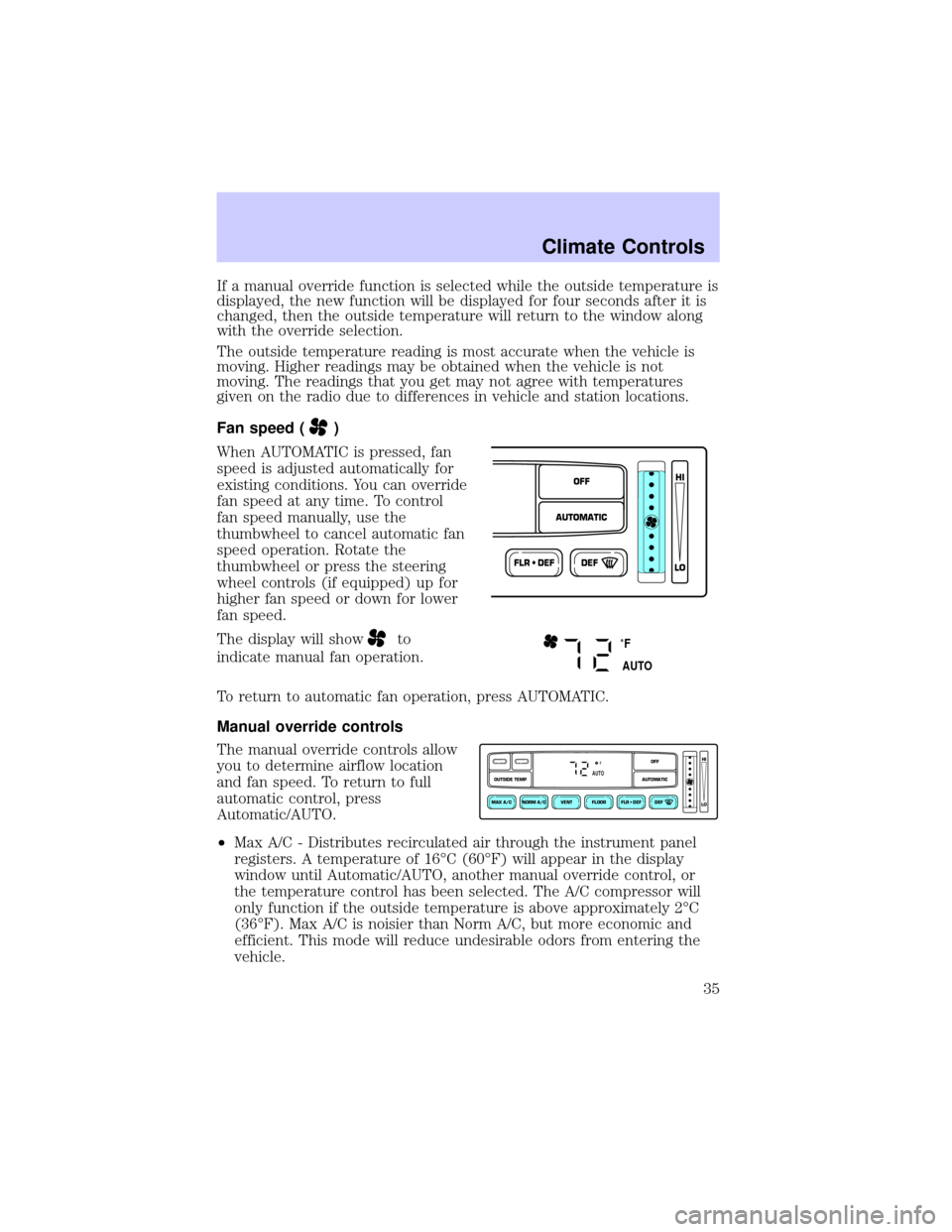
When AUTOMATIC is pressed, fan
speed is adjusted automatically for
existing conditions. You can override
fan speed at any time. To control
fan speed manually, use the
thumbwheel to cancel automatic fan
speed operation. Rotate the
thumbwheel or press the steering
wheel controls (if equipped) up for
higher fan speed or down for lower
fan speed.
The display will show
to
indicate manual fan operation.
To return to automatic fan operation, press AUTOMATIC.
Manual override controls
The manual override controls allow
you to determine airflow location
and fan speed. To return to full
automatic control, press
Automatic/AUTO.
²Max A/C - Distributes recirculated air through the instrument panel
registers. A temperature of 16ÉC (60ÉF) will appear in the display
window until Automatic/AUTO, another manual override control, or
the temperature control has been selected. The A/C compressor will
only function if the outside temperature is above approximately 2ÉC
(36ÉF). Max A/C is noisier than Norm A/C, but more economic and
efficient. This mode will reduce undesirable odors from entering the
vehicle.
FLR • DEFDEF
HI
LO
AUTOMATICOFF
˚F
AUTO
NORM A/CVENT FLOOR FLR • DEF DEF
HI
LO
MAX A/C
OUTSIDE TEMP AUTOMATICOFF
FAUTO
Climate Controls
35
Page 40 of 232

Flash to pass
Pull toward you slightly to activate
and release to deactivate.
PANEL DIMMER CONTROL
Use to adjust the brightness of the
instrument panel during headlight
and parklamp operation.
²Rotate the thumbwheel from left
to right to brighten the
instrument panel.
²Rotate the thumbwheel from right
to left to dim the instrument
panel.
Domelamp Control
The panel dimmer control also controls the domelamp operation.
²Rotate the thumbwheel fully to the right, past detent to activate the
domelamp.
²In order to turn off the domelamp, rotate the thumbwheel to the left.
AIMING THE HEADLAMPS
The headlamps on your vehicle are properly aimed at the assembly plant.
If your vehicle has been in an accident the alignment of your headlamps
should be checked by a qualified service technician.
Vertical aim adjustment
1. Park the vehicle on a level surface approximately 7.6 meters (25 feet)
from a vertical wall or screen directly in front of it.
Lights
40
Page 50 of 232
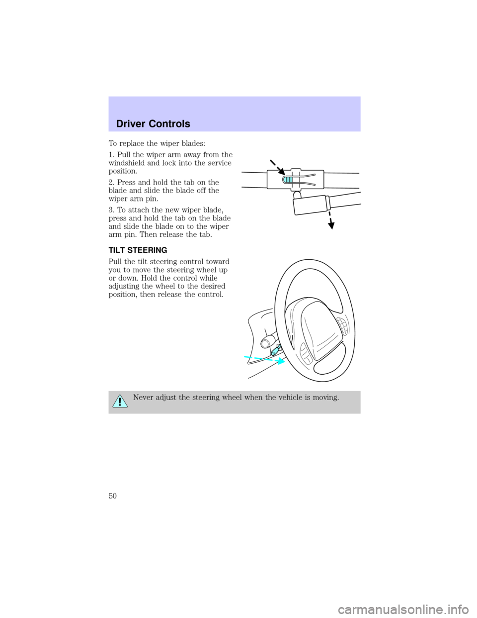
To replace the wiper blades:
1. Pull the wiper arm away from the
windshield and lock into the service
position.
2. Press and hold the tab on the
blade and slide the blade off the
wiper arm pin.
3. To attach the new wiper blade,
press and hold the tab on the blade
and slide the blade on to the wiper
arm pin. Then release the tab.
TILT STEERING
Pull the tilt steering control toward
you to move the steering wheel up
or down. Hold the control while
adjusting the wheel to the desired
position, then release the control.
Never adjust the steering wheel when the vehicle is moving.
Driver Controls
50
Page 67 of 232
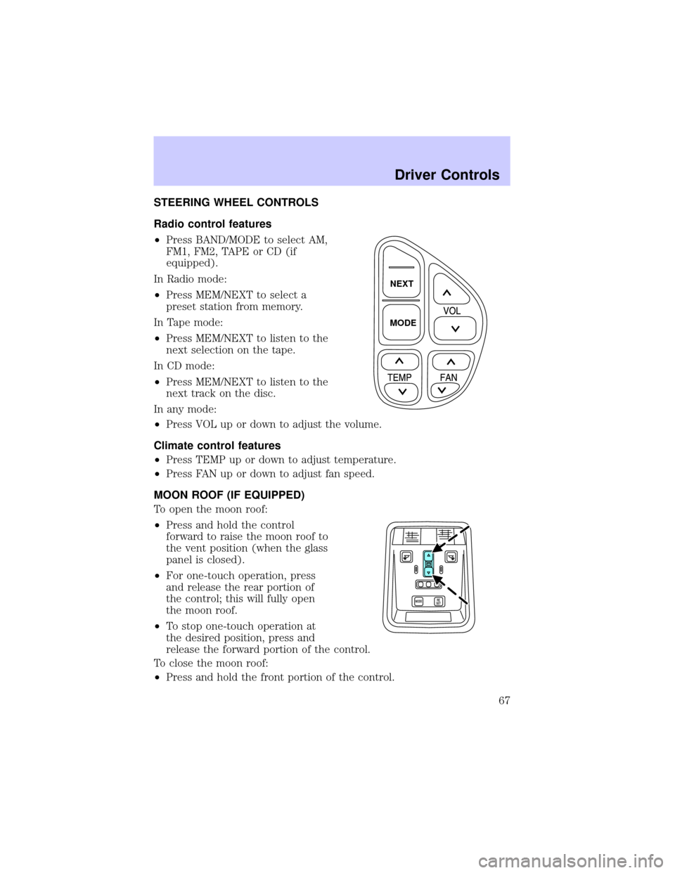
STEERING WHEEL CONTROLS
Radio control features
²Press BAND/MODE to select AM,
FM1, FM2, TAPE or CD (if
equipped).
In Radio mode:
²Press MEM/NEXT to select a
preset station from memory.
In Tape mode:
²Press MEM/NEXT to listen to the
next selection on the tape.
In CD mode:
²Press MEM/NEXT to listen to the
next track on the disc.
In any mode:
²Press VOL up or down to adjust the volume.
Climate control features
²Press TEMP up or down to adjust temperature.
²Press FAN up or down to adjust fan speed.
MOON ROOF (IF EQUIPPED)
To open the moon roof:
²Press and hold the control
forward to raise the moon roof to
the vent position (when the glass
panel is closed).
²For one-touch operation, press
and release the rear portion of
the control; this will fully open
the moon roof.
²To stop one-touch operation at
the desired position, press and
release the forward portion of the control.
To close the moon roof:
²Press and hold the front portion of the control.
NEXT
MODE
Driver Controls
67
Page 122 of 232
STARTING
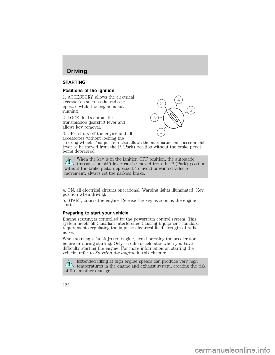
Positions of the ignition
1. ACCESSORY, allows the electrical
accessories such as the radio to
operate while the engine is not
running.
2. LOCK, locks automatic
transmission gearshift lever and
allows key removal.
3. OFF, shuts off the engine and all
accessories without locking the
steering wheel. This position also allows the automatic transmission shift
lever to be moved from the P (Park) position without the brake pedal
being depressed.
When the key is in the ignition OFF position, the automatic
transmission shift lever can be moved from the P (Park) position
without the brake pedal depressed. To avoid unwanted vehicle
movement, always set the parking brake.
4. ON, all electrical circuits operational. Warning lights illuminated. Key
position when driving.
5. START, cranks the engine. Release the key as soon as the engine
starts.
Preparing to start your vehicle
Engine starting is controlled by the powertrain control system. This
system meets all Canadian Interference-Causing Equipment standard
requirements regulating the impulse electrical field strength of radio
noise.
When starting a fuel-injected engine, avoid pressing the accelerator
before or during starting. Only use the accelerator when you have
difficulty starting the engine. For more information on starting the
vehicle, refer toStarting the enginein this chapter.
Extended idling at high engine speeds can produce very high
temperatures in the engine and exhaust system, creating the risk
of fire or other damage.
3
1
2
5
4
Driving
122
Page 126 of 232
BRAKES
Your service brakes are self-adjusting. Refer to the scheduled
maintenance guide for scheduled maintenance.
Occasional brake noise is normal and often does not indicate a
performance concern with the vehicle's brake system. In normal
operation, automotive brake systems may emit occasional or intermittent
squeal or groan noises when the brakes are applied. Such noises are
usually heard during the first few brake applications in the morning;
however, they may be heard at any time while braking and can be
aggravated by environmental conditions such as cold, heat, moisture,
road dust, salt or mud. If a ªmetal-to-metal,º ªcontinuous grindingº or
ªcontinuous squealº sound is present while braking, the brake linings
may be worn-out and should be inspected by a qualified service
technician.
If you are driving down a long or steep hill, shift to a lower gear.
Do not apply your brakes continuously, as they may overheat
and become less effective.
Anti-lock brake system (ABS)
This vehicle is equipped with an anti-lock braking system (ABS). A noise
from the hydraulic pump motor and pulsation in the pedal may be
observed during ABS braking events. Pedal pulsation coupled with noise
while braking under panic conditions or on loose gravel, bumps, wet or
snowy roads is normal and indicates proper functioning of the vehicle's
anti-lock brake system. If the vehicle has continuous vibration or shudder
in the steering wheel while braking, the vehicle should be inspected by a
qualified service technician.
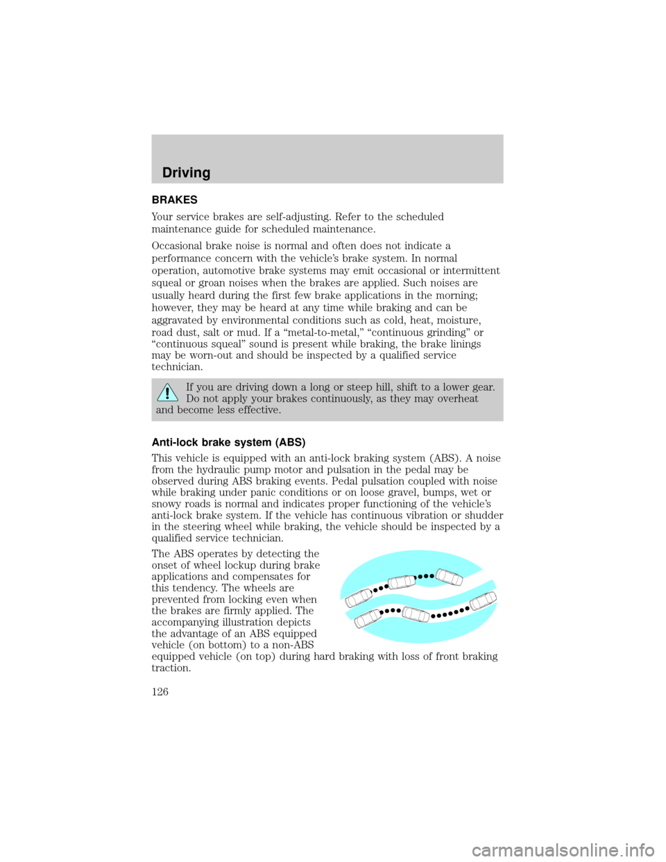
The ABS operates by detecting the
onset of wheel lockup during brake
applications and compensates for
this tendency. The wheels are
prevented from locking even when
the brakes are firmly applied. The
accompanying illustration depicts
the advantage of an ABS equipped
vehicle (on bottom) to a non-ABS
equipped vehicle (on top) during hard braking with loss of front braking
traction.
Driving
126
Page 127 of 232
Using ABS
²In an emergency or when maximum efficiency from the four-wheel
ABS is required, apply continuous force on the brake. The four wheel
ABS will be activated immediately, thus allowing you to retain full
steering control of your vehicle and, providing there is sufficient
space, will enable you to avoid obstacles and bring the vehicle to a
controlled stop.
²The anti-lock system does not reduce stopping distance. Always leave
enough room between your vehicle and the vehicle in front of you to
stop.
²We recommend that you familiarize yourself with this braking
technique. However, avoid taking any unnecessary risks.
ABS warning lampABS
TheABSwarning lamp in the instrument cluster momentarily illuminates
when the ignition is turned to the ON position. If the light does not
illuminate momentarily at start up, remains on or continues to flash, the
ABS needs to be serviced.
With the ABS light on, the anti-lock
brake system is disabled and normal
braking is still effective unless the
brake warning light also remains
illuminated with parking brake
released. (If your brake warning lamp illuminates, have your vehicle
serviced immediately.)
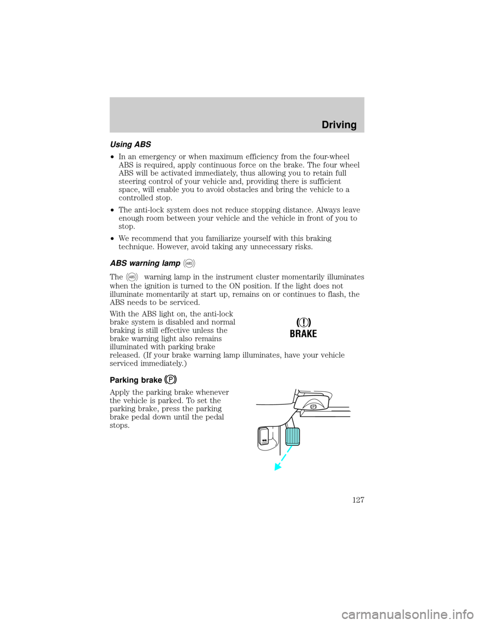
Parking brake
Apply the parking brake whenever
the vehicle is parked. To set the
parking brake, press the parking
brake pedal down until the pedal
stops.
!
BRAKE
HOOD
Driving
127
Page 128 of 232
The BRAKE warning lamp in the
instrument cluster illuminates and
remains illuminated (when the
ignition is turned ON) until the
parking brake is released.
Always set the parking brake fully and make sure that the
gearshift is securely latched in P (Park).
The parking brake is not recommended to stop a moving vehicle.
However, if the normal brakes fail, the parking brake can be used to stop
your vehicle in an emergency. Since the parking brake applies only the
rear brakes, the vehicle's stopping distance will increase greatly and the
handling of your vehicle will be adversely affected.
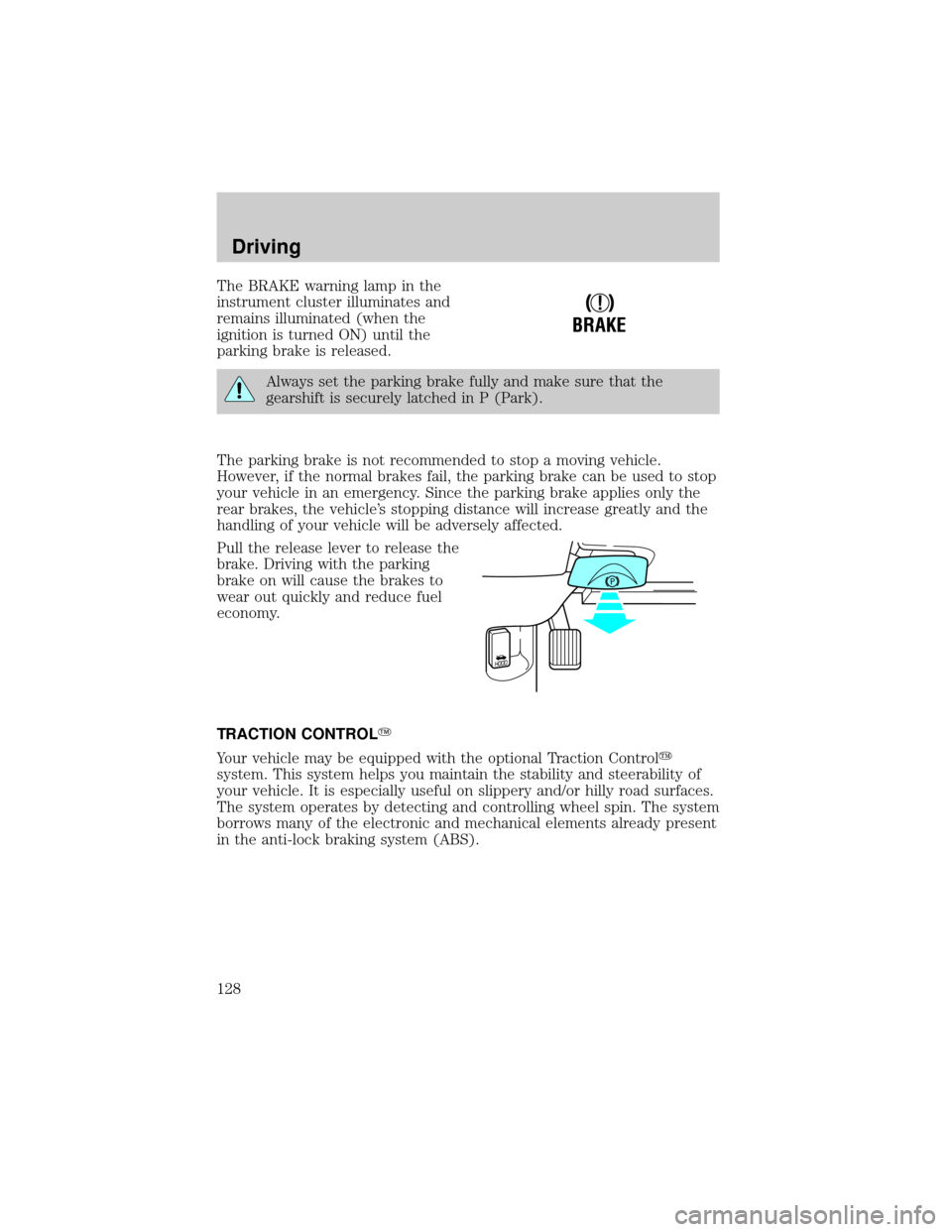
Pull the release lever to release the
brake. Driving with the parking
brake on will cause the brakes to
wear out quickly and reduce fuel
economy.
TRACTION CONTROLY
Your vehicle may be equipped with the optional Traction Controly
system. This system helps you maintain the stability and steerability of
your vehicle. It is especially useful on slippery and/or hilly road surfaces.
The system operates by detecting and controlling wheel spin. The system
borrows many of the electronic and mechanical elements already present
in the anti-lock braking system (ABS).
!
BRAKE
Driving
128