Battery Mercury Mountaineer 1998 Owner's Manuals
[x] Cancel search | Manufacturer: MERCURY, Model Year: 1998, Model line: Mountaineer, Model: Mercury Mountaineer 1998Pages: 216, PDF Size: 1.72 MB
Page 10 of 216

Anti-theft system (if equipped)
Refer toAnti-theft systemin the
Controls and featureschapter.
Charging system
Momentarily illuminates when the
ignition is turned ON and the
engine is off. The light also
illuminates when the battery is not
charging properly, requiring
electrical system service.
Check gage
Illuminates when the key is in the
ON position and the engine coolant
temperature is high, the engine oil
pressure is low or the fuel level is
near empty. Refer toEngine
coolant temperature gauge,
Engine oil pressure gaugeor
Fuel gaugein this chapter for
more information.
Door ajar
Illuminates when the ignition
switch is in the ON or START
position and any door is open.
THEFT
CHECK
GAGE
DOOR
AJAR
Instrumentation
10
Page 14 of 216

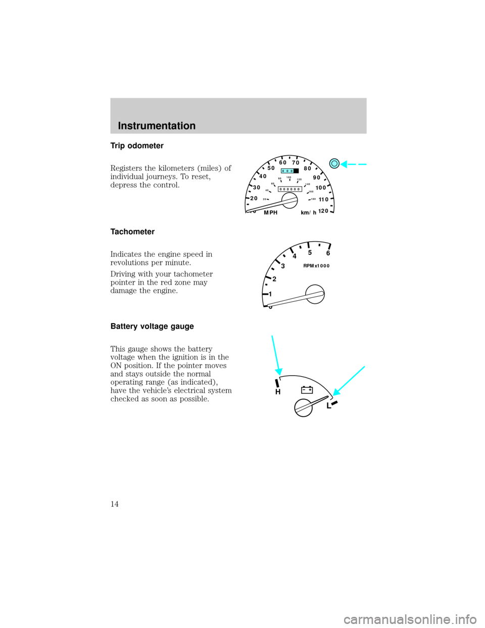
Trip odometer
Registers the kilometers (miles) of
individual journeys. To reset,
depress the control.
Tachometer
Indicates the engine speed in
revolutions per minute.
Driving with your tachometer
pointer in the red zone may
damage the engine.
Battery voltage gauge
This gauge shows the battery
voltage when the ignition is in the
ON position. If the pointer moves
and stays outside the normal
operating range (as indicated),
have the vehicle's electrical system
checked as soon as possible.
10MPH 205060
70
304080
90
km/h
0 0 0
10 100
1
20
1
0 0 0 0 0 0406080100
120
140
160
180
20
0 12345
6
RPMx1000
L
H
Instrumentation
14
Page 48 of 216

Replacing the battery
The transmitter is powered by one
coin type three-volt lithium battery
CR2032 or equivalent. Typical
operating range will allow you to
be up to 10 meters (33 feet) away
from your vehicle. A decrease in
operating range can be caused by:
²battery weakness due to time
and use
²weather conditions
²nearby radio towers
²structures around the vehicle
²other vehicles parked next to
the vehicle
To replace the battery:
1. Twist a thin coin between the
two halves of the transmitter near
the key ring. DO NOT TAKE THE
FRONT PART OF THE
TRANSMITTER APART.
2. Place the positive (+) side of
new battery in the same
orientation. Refer to the diagram
inside the transmitter unit.
3. Snap the two halves back
together.
Controls and features
48
Page 50 of 216

door(s) or sound the personal
alarm.
The system automatically turns off
after 25 seconds or when the
ignition is turned to the START or
ACC position. The dome lamp
switch (if equipped) mustnotbe
set to the OFF position for the
illuminated entry system to
operate.
The inside lights will not turn off
if:
²they have been turned on with
the dimmer control or
²any door is open.
Battery saver will shut off the
interior lamps 45 minutes after the
last door is closed.
Autolock
Autolock is a feature that will
automatically lock all doors when:
²all vehicle doors, liftgate and
liftgate window are fully closed
²the ignition key is in the ON
position
²you shift into or through R
(Reverse)
²the brake pedal is released
The autolock feature repeats when:
²any door is opened and then
closed
²the brake pedal is released
Deactivating autolock
Before following the activation or
deactivation procedures, make sure
Controls and features
50
Page 140 of 216

Fuse/Relay
LocationFuse Amp
RatingDescription
14 10A 4 Wheel Anti-Lock Brake System
(4WABS) Module, 4WABS Main
Relay
15 7.5A Instrument Cluster
16 30A Windshield Wiper Motor, Wiper
Hi-Lo Relay, Wiper Run/Park
Relay
17 7.5A Cigar Lighter
18 15A Drivers Unlock Relay, All unlock
Relay, All Lock Relay
19 25A PCM Power Diode
20 7.5A RAP Module, Generic Electronic
Module (GEM), Radio
21 15A Flasher (Hazard)
22 20A Auxiliary Power Socket
23 15A Turn Signals
24 - Not Used
25 7.5A Generic Electronic Module
(GEM), Instrument Cluster
26 10A Battery Saver Relay, Electronic
Shift Relay, Interior Lamp Relay,
Power Window Relay, Electronic
Shift Control Module,
Transmission Control
27 15A Switch, DRL, Backup Lamps
Switch, DTR Sensor, Instrument
Illumination Dimming Module,
Dome/Map Lamp, GEM, Electric
Shift, Interior Lights, Glove Box
Lamp and Switch
28 7.5A Generic Electronic Module
(GEM), Radio
29 15A Radio
Roadside emergencies
140
Page 141 of 216

Fuse/Relay
LocationFuse Amp
RatingDescription
30 15A Park Lamp/Trailer Tow Relay
31 Ð NOT USED
32 10A Rear Blower
33 15A Headlamps, Daytime Running
Lamps (DRL) Module, Instrument
Cluster
34 7.5A Rear Integrated Control Panel, CD
35 10A RABS Test Connector
36 7.5A CD, Rear Integrated Control
Panel, Memory Seat, Message
Center
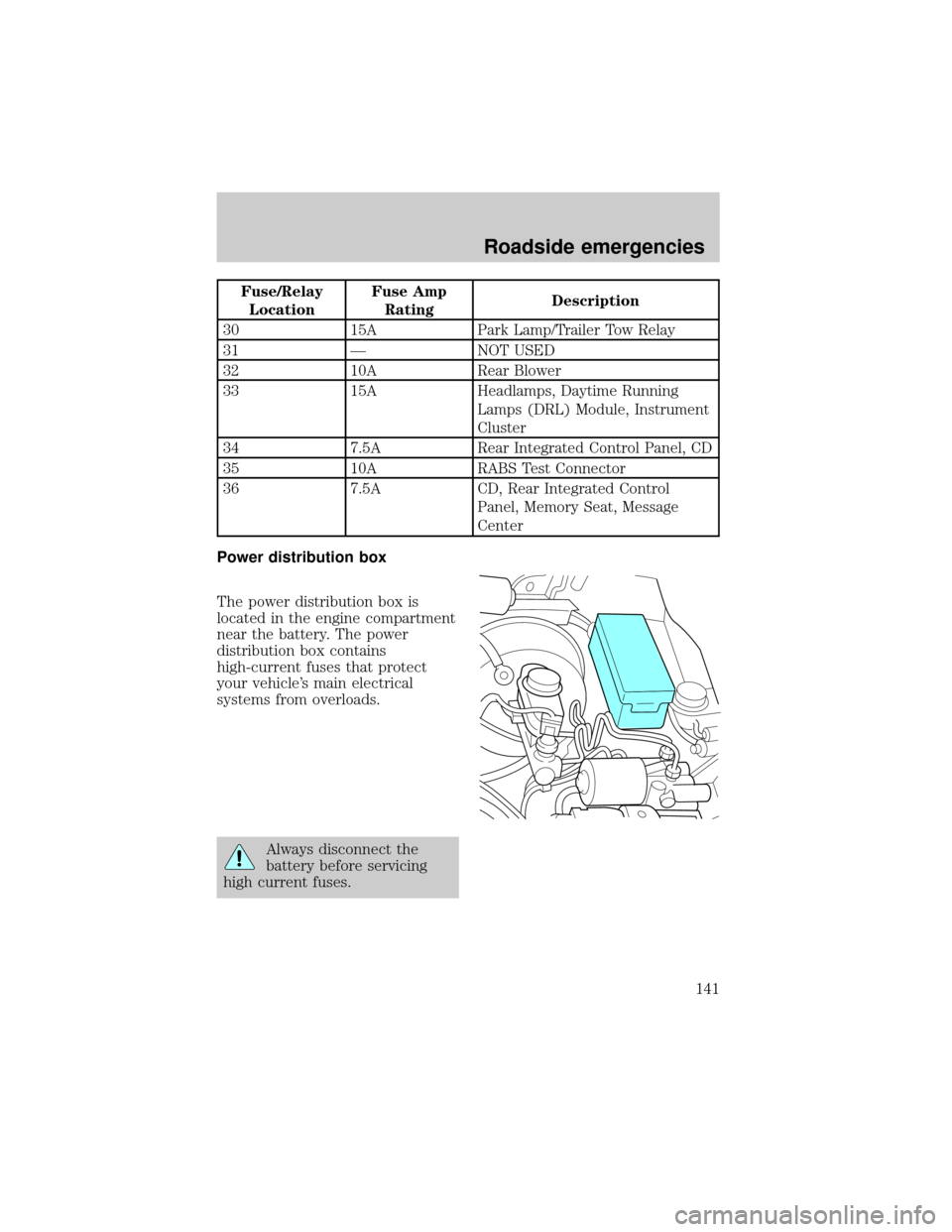
Power distribution box
The power distribution box is
located in the engine compartment
near the battery. The power
distribution box contains
high-current fuses that protect
your vehicle's main electrical
systems from overloads.
Always disconnect the
battery before servicing
high current fuses.
Roadside emergencies
141
Page 142 of 216

Always replace the cover
to the Power Distribution
Box before reconnecting the
battery or refilling fluid
reservoirs.
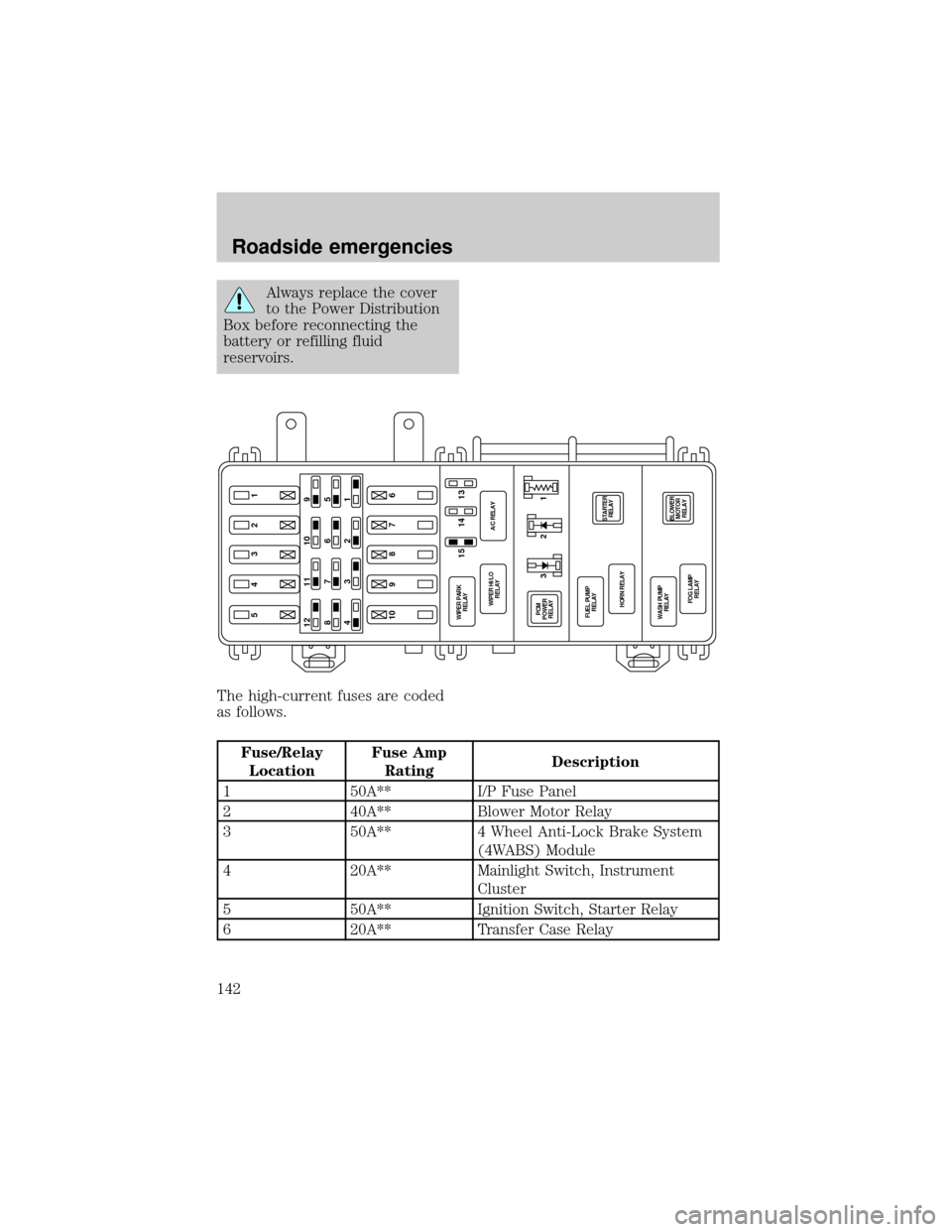
The high-current fuses are coded
as follows.
Fuse/Relay
LocationFuse Amp
RatingDescription
1 50A** I/P Fuse Panel
2 40A** Blower Motor Relay
3 50A** 4 Wheel Anti-Lock Brake System
(4WABS) Module
4 20A** Mainlight Switch, Instrument
Cluster
5 50A** Ignition Switch, Starter Relay
6 20A** Transfer Case Relay
5432110 9 8 7 612 11 10 9
876 5
432 1
14 15 13
BLOWER
MOTOR
RELAYSTARTER
RELAY
FOG LAMP
RELAY WASH PUMP
RELAYHORN RELAY FUEL PUMP
RELAY PCM
POWER
RELAY WIPER PARK
RELAY
WIPER HI/LO
RELAYA/C RELAY
321
Roadside emergencies
142
Page 149 of 216

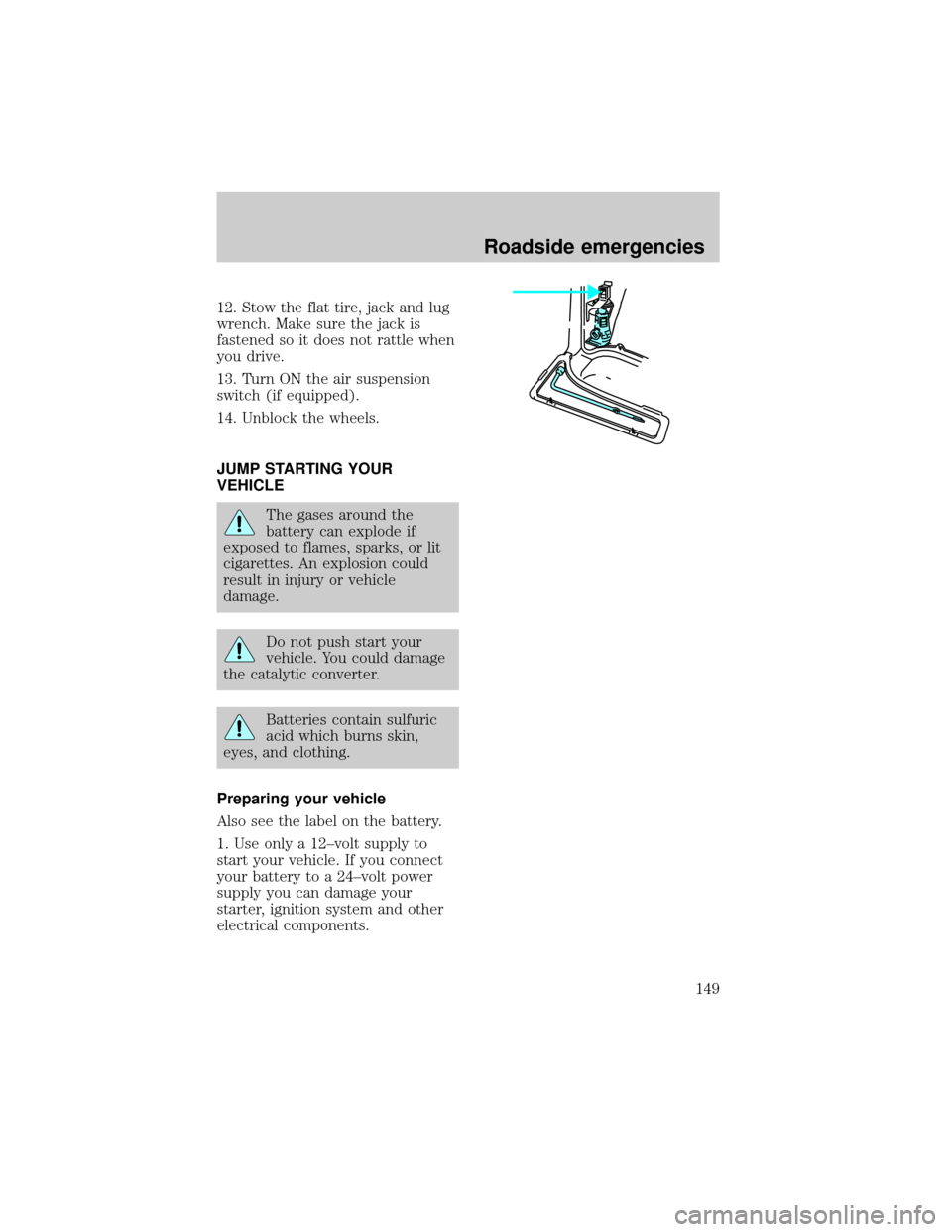
12. Stow the flat tire, jack and lug
wrench. Make sure the jack is
fastened so it does not rattle when
you drive.
13. Turn ON the air suspension
switch (if equipped).
14. Unblock the wheels.
JUMP STARTING YOUR
VEHICLE
The gases around the
battery can explode if
exposed to flames, sparks, or lit
cigarettes. An explosion could
result in injury or vehicle
damage.
Do not push start your
vehicle. You could damage
the catalytic converter.
Batteries contain sulfuric
acid which burns skin,
eyes, and clothing.
Preparing your vehicle
Also see the label on the battery.
1. Use only a 12±volt supply to
start your vehicle. If you connect
your battery to a 24±volt power
supply you can damage your
starter, ignition system and other
electrical components.
Roadside emergencies
149
Page 150 of 216

2. Do not disconnect the battery of
the disabled vehicle as this could
damage the vehicle's electrical
system.
3. Park the booster vehicle close to
the hood of the disabled vehicle
making sure theydo nottouch.
Set the parking brake on both
vehicles and stay clear of the
engine cooling fan and other
moving parts.
4. Check all battery terminals and
remove any excessive corrosion
before you attach the battery
cables.
5. Turn the heater fan on in both
vehicles to protect any electrical
surges. Turn all other accessories
off.
Connecting the jumper cables
1. Position the vehicles so that
they do not touch one another.
2. Switch off the engine. Switch off
any unnecessary electrical
equipment.
3. Connect the positive (+)
terminal of the discharged battery
(1) to the positive (+) terminal of
the booster battery (2).
4. Connect one end of the second
lead to the negative (-) terminal of
the booster battery (3) and the
other end to a metal part of the
engine to be started (4), not to the
negative (-) terminal of the
discharged battery.
+–
+–
14
3
2
Roadside emergencies
150
Page 151 of 216

5. Make sure that the jump leads
are clear of moving parts of the
engine.
Do not connect the end of
the second cable to the
negative (-) terminal of the
battery to be jumped. A spark
may cause an explosion of the
gases that surround the battery.
Jump starting
1. Start the booster vehicle and
run the engine at moderately
increased speed.
2. Start the engine of the vehicle
with the discharged battery.
3. Once the engine has been
started, run both vehicles for a
further three minutes before
disconnecting the leads.
Removing the jumper cables
1. Remove the jumper cables in
reverse order. Take the cable off
the metallic surface (1) first,
followed by the cable on the
negative (-) booster battery
terminal (2).
2. Remove the cable from the
positive (+) terminal of the booster
battery (3) and then the
discharged battery (4).
3. After the disabled vehicle has
been started, allow it to idle for a
while so the engine can ªrelearnº
its idle conditions.
+–
+–
41
2
3
Roadside emergencies
151