lock Mercury Mountaineer 1999 s User Guide
[x] Cancel search | Manufacturer: MERCURY, Model Year: 1999, Model line: Mountaineer, Model: Mercury Mountaineer 1999Pages: 248, PDF Size: 1.74 MB
Page 70 of 248

To set the minute, press the
clock/RDS control until SELECT
MIN is displayed and press:
²
to decrease minutes and
²
to increase minutes.
Radio Data System (RDS) feature
This feature allows your audio
system to receive text information
from RDS-equipped FM radio
stations.
Press and hold the control for three
seconds to turn the feature on or
off. Press the control to scroll
through the following selections:
AUTO
RDS
SEL
AUTO
RDS
Controls and features
70
Page 77 of 248
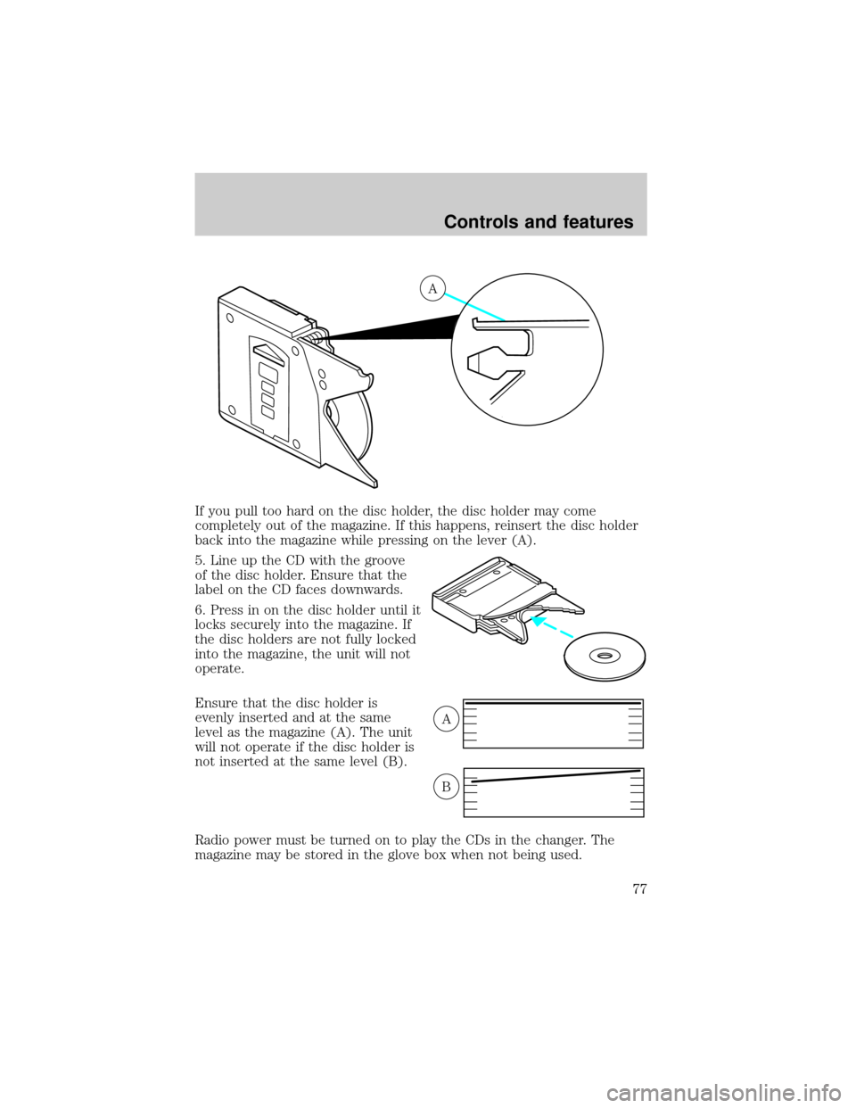
If you pull too hard on the disc holder, the disc holder may come
completely out of the magazine. If this happens, reinsert the disc holder
back into the magazine while pressing on the lever (A).
5. Line up the CD with the groove
of the disc holder. Ensure that the
label on the CD faces downwards.
6. Press in on the disc holder until it
locks securely into the magazine. If
the disc holders are not fully locked
into the magazine, the unit will not
operate.
Ensure that the disc holder is
evenly inserted and at the same
level as the magazine (A). The unit
will not operate if the disc holder is
not inserted at the same level (B).
Radio power must be turned on to play the CDs in the changer. The
magazine may be stored in the glove box when not being used.
A
A
B
Controls and features
77
Page 80 of 248
²Station overload.Weak signals are sometimes captured by stronger
signals when you pass a broadcast tower. A stronger signal may
temporarily overtake a weaker signal and play while the weak station
frequency is displayed.
The audio system automatically switches to single channel reception if it
will improve the reception of a station normally received in stereo.
Audio system warranties and service
Refer to the ªWarranty Guideº for audio system warranty information.
If service is necessary, see your dealer or a qualified technician.
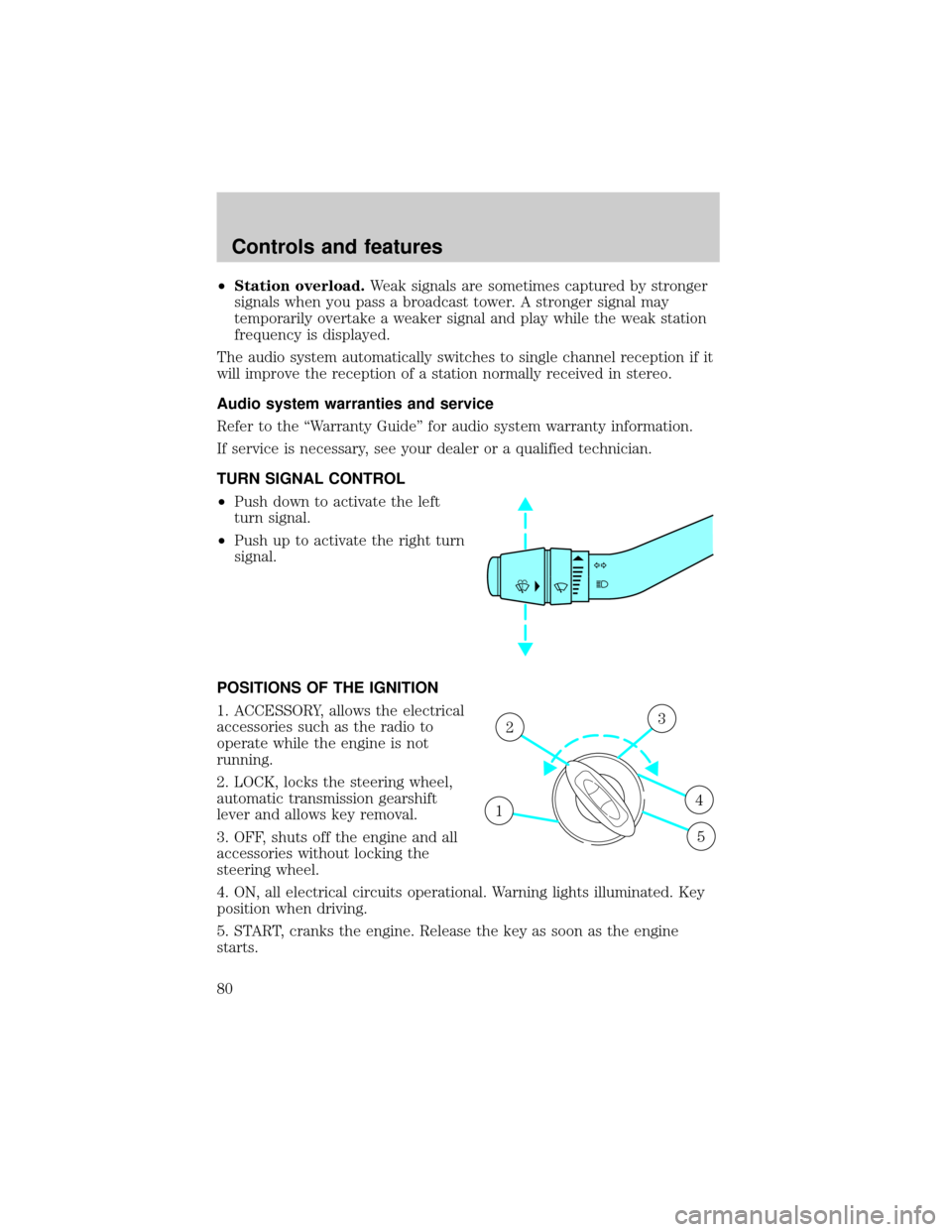
TURN SIGNAL CONTROL
²Push down to activate the left
turn signal.
²Push up to activate the right turn
signal.
POSITIONS OF THE IGNITION
1. ACCESSORY, allows the electrical
accessories such as the radio to
operate while the engine is not
running.
2. LOCK, locks the steering wheel,
automatic transmission gearshift
lever and allows key removal.
3. OFF, shuts off the engine and all
accessories without locking the
steering wheel.
4. ON, all electrical circuits operational. Warning lights illuminated. Key
position when driving.
5. START, cranks the engine. Release the key as soon as the engine
starts.
1
23
4
5
Controls and features
80
Page 85 of 248
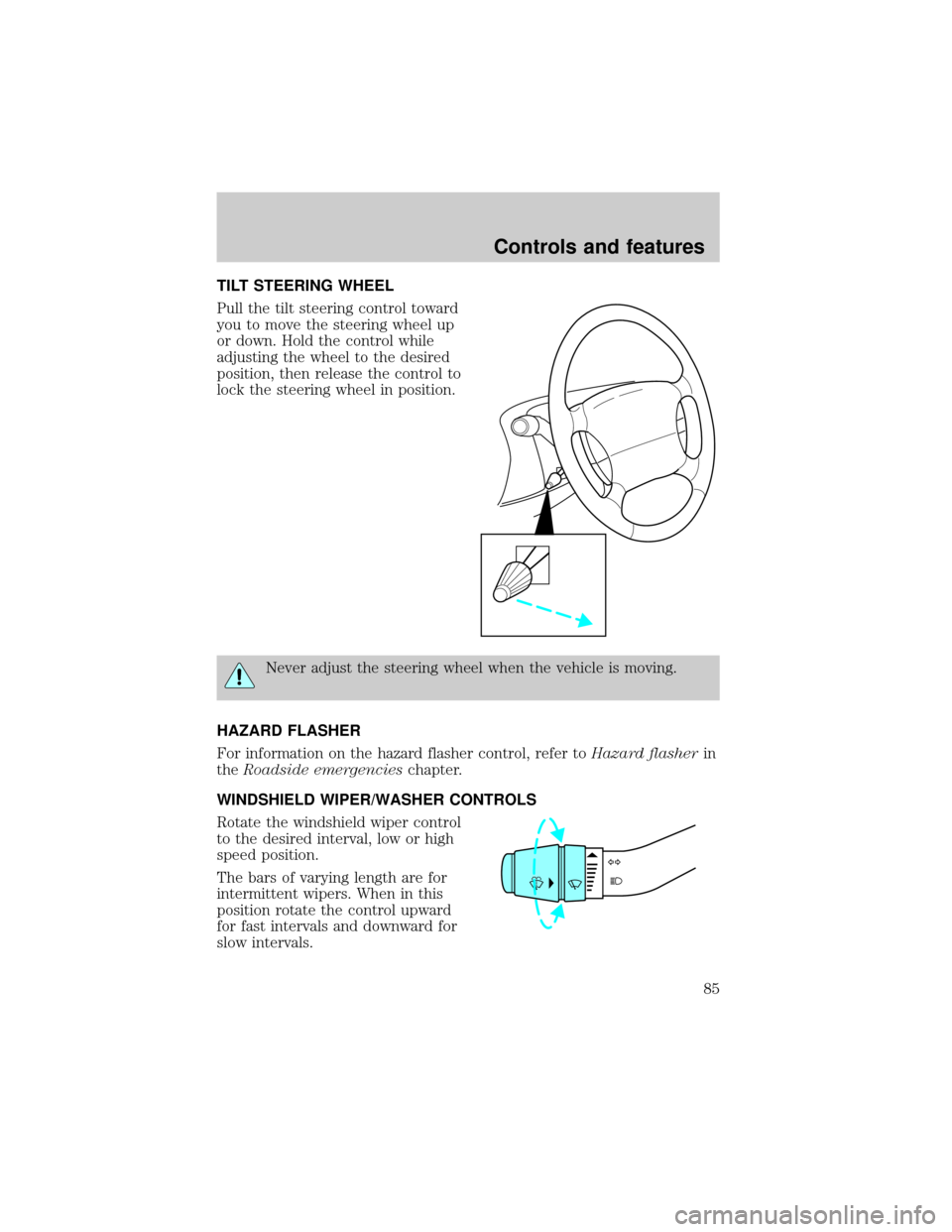
TILT STEERING WHEEL
Pull the tilt steering control toward
you to move the steering wheel up
or down. Hold the control while
adjusting the wheel to the desired
position, then release the control to
lock the steering wheel in position.
Never adjust the steering wheel when the vehicle is moving.
HAZARD FLASHER
For information on the hazard flasher control, refer toHazard flasherin
theRoadside emergencieschapter.
WINDSHIELD WIPER/WASHER CONTROLS
Rotate the windshield wiper control
to the desired interval, low or high
speed position.
The bars of varying length are for
intermittent wipers. When in this
position rotate the control upward
for fast intervals and downward for
slow intervals.
Controls and features
85
Page 92 of 248

Compass calibration adjustment
Perform this adjustment in an open
area free from steel structures and
high voltage lines:
²Press and hold the MODE control
until CAL appears in the display
(approximately eight seconds)
and release.
²Drive the vehicle slowly (less
than 5 km/h [3 mph]) in circles
until CAL indicator turns off in
about 2±3 complete circles.
HOMELINKTUNIVERSAL TRANSCEIVER WITH TRAVELNOTET
(IF EQUIPPED)
The HomeLinktUniversal Transceiver, located on the driver's visor,
provides a convenient way to replace up to three hand-held transmitters
with a single built-in device. This feature will learn the radio frequency
codes of most current transmitters to operate garage doors, entry gates,
security systems, entry door locks, and home or office lighting.
When programming your HomeLinktUniversal Transceiver, to a
garage door or gate be sure that people and objects are out of
the way to prevent potential harm or damage.
Do not use the HomeLinktUniversal Transceiver with any garage door
opener that lacks safety stop and reverse features as required by U.S.
federal safety standards (this includes any garage door opener model
manufactured before April 1, 1982). A garage door which cannot detect
an object, signaling the door to stop and reverse, does not meet current
U.S. federal safety standards. For more information on this matter, call
toll-free: 1±800±355±3515 or on the Internet atHomeLink.jci.com.
LAMPMODELAMP
CAL
Controls and features
92
Page 100 of 248

Window lock
The window lock feature allows only
the driver to operate the power
windows.
To lock out all the window controls
except for the driver's press the left
side of the control. Press the right side to restore the window controls.
POWER DOOR LOCKS
Press U to unlock all doors and L to
lock all doors.
CHILDPROOF DOOR LOCKS
When these locks are set, the rear
doors cannot be opened from the
inside. The rear doors can be
opened from the outside when the
doors are unlocked.
The childproof locks are located on
rear edge of each rear door and
must be set separately for each
door. Setting the lock for one door
will not automatically set the lock
for both doors.
Move lock control up to engage the lock. Move control down to
disengage childproof locks.
WINDOW LOCK
UL
Controls and features
100
Page 101 of 248
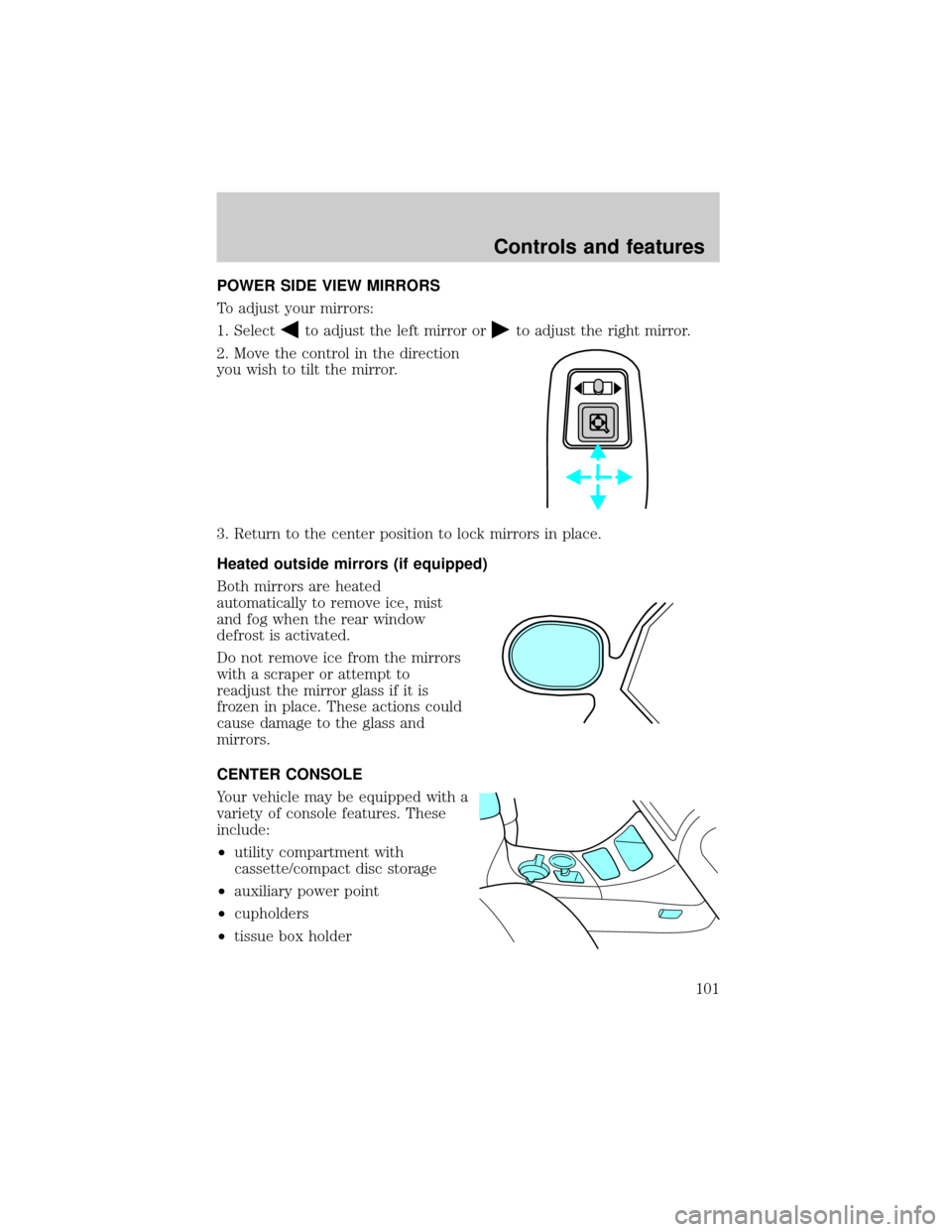
POWER SIDE VIEW MIRRORS
To adjust your mirrors:
1. Select
to adjust the left mirror orto adjust the right mirror.
2. Move the control in the direction
you wish to tilt the mirror.
3. Return to the center position to lock mirrors in place.
Heated outside mirrors (if equipped)
Both mirrors are heated
automatically to remove ice, mist
and fog when the rear window
defrost is activated.
Do not remove ice from the mirrors
with a scraper or attempt to
readjust the mirror glass if it is
frozen in place. These actions could
cause damage to the glass and
mirrors.
CENTER CONSOLE
Your vehicle may be equipped with a
variety of console features. These
include:
²utility compartment with
cassette/compact disc storage
²auxiliary power point
²cupholders
²tissue box holder
Controls and features
101
Page 103 of 248
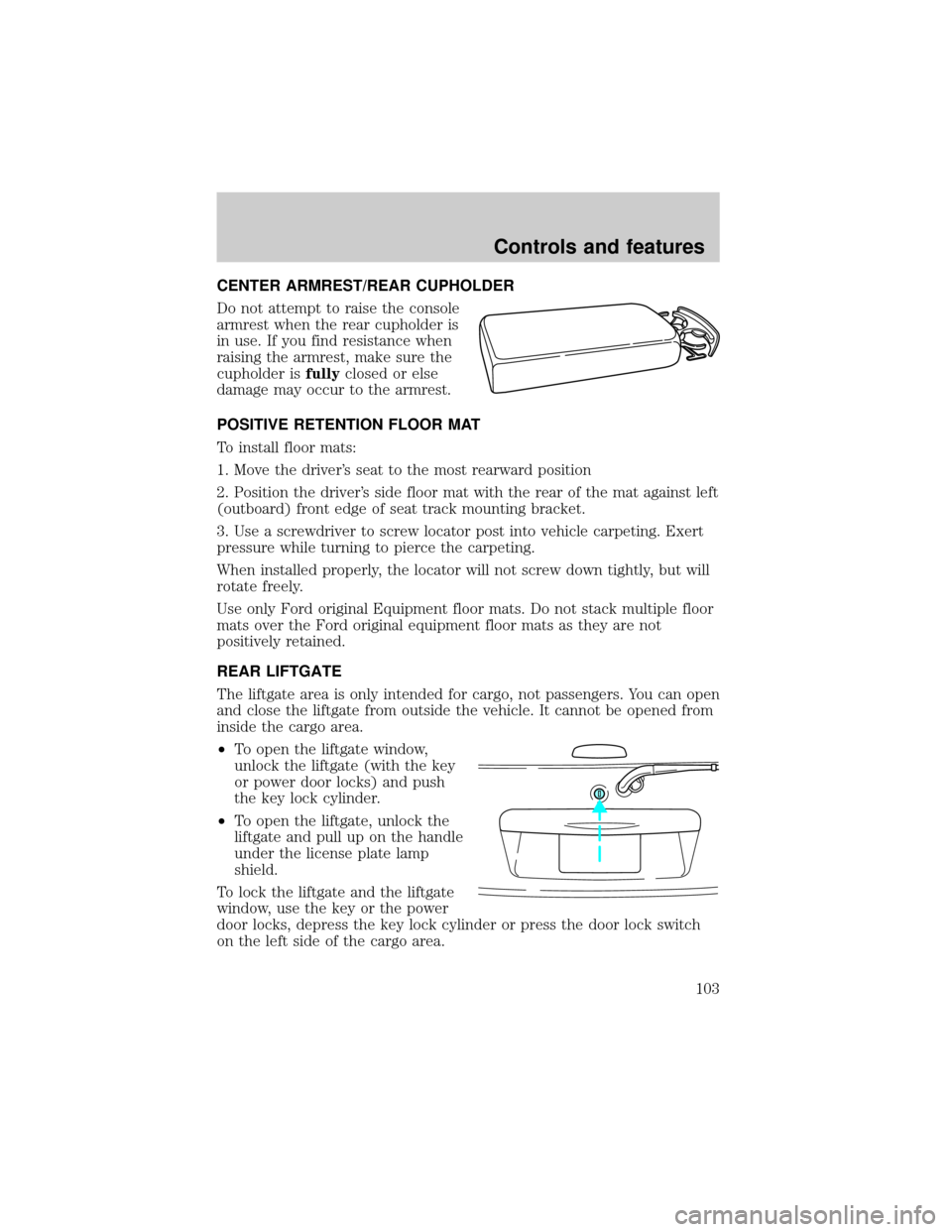
CENTER ARMREST/REAR CUPHOLDER
Do not attempt to raise the console
armrest when the rear cupholder is
in use. If you find resistance when
raising the armrest, make sure the
cupholder isfullyclosed or else
damage may occur to the armrest.
POSITIVE RETENTION FLOOR MAT
To install floor mats:
1. Move the driver's seat to the most rearward position
2. Position the driver's side floor mat with the rear of the mat against left
(outboard) front edge of seat track mounting bracket.
3. Use a screwdriver to screw locator post into vehicle carpeting. Exert
pressure while turning to pierce the carpeting.
When installed properly, the locator will not screw down tightly, but will
rotate freely.
Use only Ford original Equipment floor mats. Do not stack multiple floor
mats over the Ford original equipment floor mats as they are not
positively retained.
REAR LIFTGATE
The liftgate area is only intended for cargo, not passengers. You can open
and close the liftgate from outside the vehicle. It cannot be opened from
inside the cargo area.
²To open the liftgate window,
unlock the liftgate (with the key
or power door locks) and push
the key lock cylinder.
²To open the liftgate, unlock the
liftgate and pull up on the handle
under the license plate lamp
shield.
To lock the liftgate and the liftgate
window, use the key or the power
door locks, depress the key lock cylinder or press the door lock switch
on the left side of the cargo area.
Controls and features
103
Page 105 of 248
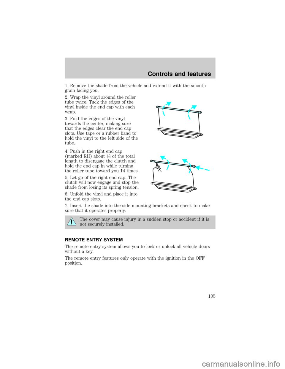
1. Remove the shade from the vehicle and extend it with the smooth
grain facing you.
2. Wrap the vinyl around the roller
tube twice. Tuck the edges of the
vinyl inside the end cap with each
wrap.
3. Fold the edges of the vinyl
towards the center, making sure
that the edges clear the end cap
slots. Use tape or a rubber band to
hold the vinyl to the left side of the
tube.
4. Push in the right end cap
(marked RH) about
1¤4of the total
length to disengage the clutch and
hold the end cap in while turning
the roller tube toward you 14 times.
5. Let go of the right end cap. The
clutch will now engage and stop the
shade from losing its spring tension.
6. Unfold the vinyl and place it into
the end cap slots.
7. Insert the shade into the side mounting brackets and check to make
sure that it operates properly.
The cover may cause injury in a sudden stop or accident if it is
not securely installed.
REMOTE ENTRY SYSTEM
The remote entry system allows you to lock or unlock all vehicle doors
without a key.
The remote entry features only operate with the ignition in the OFF
position.
Controls and features
105
Page 106 of 248

Unlocking the doors
Press this control to unlock the
driver's door. The interior lamps will
illuminate.
Press the control a second time
within five seconds to unlock all
doors.
Locking the doors
Press this control to lock all doors.
To confirm all doors are closed and
locked, press the control a second
time within five seconds. The doors
will lock again, the horn will chirp
and the lamps will flash.
If any of the doors are ajar, the horn
will make two quick chirps,
reminding you to properly close all
doors.
Sounding a panic alarm
Press this control to activate the
alarm.
To deactivate the alarm, press the
control again or turn the ignition to
ACC or ON.
This device complies with part 15 of
the FCC rules and with RS-210 of
Industry Canada. Operation is
subject to the following two
conditions: (1) This device may not
cause harmful interference, and (2) This device must accept any
interference received, including interference that may cause undesired
operation.
Controls and features
106