check engine light Mercury Mountaineer 2003 Owner's Manuals
[x] Cancel search | Manufacturer: MERCURY, Model Year: 2003, Model line: Mountaineer, Model: Mercury Mountaineer 2003Pages: 264, PDF Size: 2.5 MB
Page 10 of 264
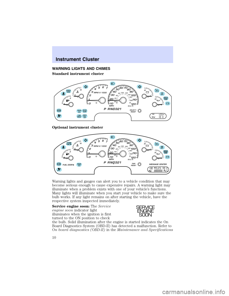
WARNING LIGHTS AND CHIMES
Standard instrument cluster
Optional instrument cluster
Warning lights and gauges can alert you to a vehicle condition that may
become serious enough to cause expensive repairs. A warning light may
illuminate when a problem exists with one of your vehicle’s functions.
Many lights will illuminate when you start your vehicle to make sure the
bulb works. If any light remains on after starting the vehicle, have the
respective system inspected immediately.
Service engine soon:TheService
engine soonindicator light
illuminates when the ignition is first
turned to the ON position to check
the bulb. Solid illumination after the engine is started indicates the On
Board Diagnostics System (OBD-II) has detected a malfunction. Refer to
On board diagnostics (OBD-II)in theMaintenance and Specifications
O/D
OFF
DOOR
AJARCHECK
GAGE
CHECK
FUEL
CAPLOW
WASH
BRAKE
SERVICE
ENGINE
SOON
TRIP
SERVICE
ENGINE
SOON
Instrument Cluster
Instrument Cluster
10
Page 11 of 264

chapter. If the light is blinking, engine misfire is occurring which could
damage your catalytic converter. Drive in a moderate fashion (avoid
heavy acceleration and deceleration) and have your vehicle serviced
immediately.
Under engine misfire conditions, excessive exhaust temperatures
could damage the catalytic converter, the fuel system, interior
floor coverings or other vehicle components, possibly causing a fire.
Check fuel cap (if equipped):
Illuminates when the fuel cap may
not be properly installed. Continued
driving with this light on may cause
the Service engine soon light to
come on, refer toFuel filler capin theMaintenance and
Specificationschapter.
Brake system warning light:To
confirm the brake system warning
light is functional, it will
momentarily illuminate when the
ignition is turned to the ON position when the engine is not running, or
in a position between ON and START, or by applying the parking brake
when the ignition is turned to the ON position. If the brake system
warning light does not illuminate at this time, seek service immediately
from your dealership. Illumination after releasing the parking brake
indicates low brake fluid level and the brake system should be inspected
immediately by your servicing dealership.
Driving a vehicle with the brake system warning light on is
dangerous. A significant decrease in braking performance may
occur. It will take you longer to stop the vehicle. Have the vehicle
checked by your dealer immediately.
CHECK
FUEL
CAP
Instrument Cluster
11
Page 12 of 264
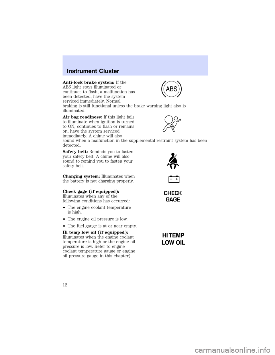
Anti-lock brake system:If the
ABS light stays illuminated or
continues to flash, a malfunction has
been detected, have the system
serviced immediately. Normal
braking is still functional unless the brake warning light also is
illuminated.
Air bag readiness:If this light fails
to illuminate when ignition is turned
to ON, continues to flash or remains
on, have the system serviced
immediately. A chime will also
sound when a malfunction in the supplemental restraint system has been
detected.
Safety belt:Reminds you to fasten
your safety belt. A chime will also
sound to remind you to fasten your
safety belt.
Charging system:Illuminates when
the battery is not charging properly.
Check gage (if equipped):
Illuminates when any of the
following conditions has occurred:
•The engine coolant temperature
is high.
•The engine oil pressure is low.
•The fuel gauge is at or near empty.
Hi temp low oil (if equipped):
Illuminates when the engine coolant
temperature is high or the engine oil
pressure is low. Refer to engine
coolant temperature gauge or engine
oil pressure gauge in this chapter).
ABS
CHECK
GAGE
Instrument Cluster
12
Page 16 of 264
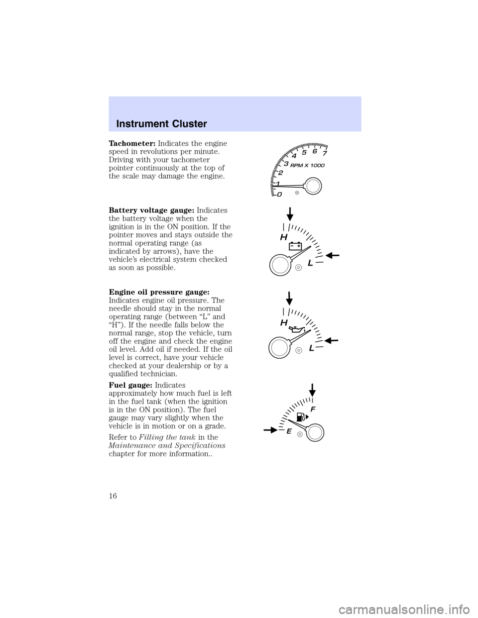
Tachometer:Indicates the engine
speed in revolutions per minute.
Driving with your tachometer
pointer continuously at the top of
the scale may damage the engine.
Battery voltage gauge:Indicates
the battery voltage when the
ignition is in the ON position. If the
pointer moves and stays outside the
normal operating range (as
indicated by arrows), have the
vehicle’s electrical system checked
as soon as possible.
Engine oil pressure gauge:
Indicates engine oil pressure. The
needle should stay in the normal
operating range (between“L”and
“H”). If the needle falls below the
normal range, stop the vehicle, turn
off the engine and check the engine
oil level. Add oil if needed. If the oil
level is correct, have your vehicle
checked at your dealership or by a
qualified technician.
Fuel gauge:Indicates
approximately how much fuel is left
in the fuel tank (when the ignition
is in the ON position). The fuel
gauge may vary slightly when the
vehicle is in motion or on a grade.
Refer toFilling the tankin the
Maintenance and Specifications
chapter for more information..
Instrument Cluster
16
Page 142 of 264

STARTING
Positions of the ignition
1. OFF/LOCK, shuts off the engine
and all accessories/locks the steering
wheel, gearshift lever and allows key
removal.
2. ACC, allows the electrical
accessories such as the radio to
operate while the engine is not
running. This position also unlocks
the steering wheel.
3. ON, all electrical circuits
operational. Warning lights illuminated. Key position when driving.
4. START, cranks the engine. Release the key as soon as the engine
starts.
Important safety precautions
When the engine starts, the idle RPM runs faster to warm the engine. If
the engine idle speed does not slow down automatically, have the vehicle
checked.
Before starting the vehicle:
1. Make sure all occupants buckle their safety belts. For more
information on safety belts and their proper usage, refer to theSeating
and safety restraintschapter.
2. Make sure the headlamps and electrical accessories are off.
•Make sure the parking brake is
set.
4
3
2
1
Driving
Driving
142
Page 143 of 264

•Make sure the gearshift is in P
(Park).
•Turn the key to 3 (ON) without
turning the key to 4 (START).
Make sure the corresponding lights illuminate or illuminate briefly. If a
light fails to illuminate, have the vehicle serviced.
•If the driver’s safety belt is fastened, the
light may not illuminate.
4
3
2
1
O/D
OFF
DOOR
AJARCHECK
GAGE
CHECK
FUEL
CAPLOW
WASH
BRAKE
SERVICE
ENGINE
SOON
TRIP
Driving
143
Page 184 of 264

Preparing your vehicle
When the battery is disconnected or a new battery is installed, the
transmission must relearn its shift strategy. As a result, the transmission
may have firm and/or soft shifts. This operation is considered normal and
will not affect function or durability of the transmission. Over time, the
adaptive learning process will fully update transmission operation.
1.Use only a 12–volt supply to start your vehicle.
2. Do not disconnect the battery of the disabled vehicle as this could
damage the vehicle’s electrical system.
3. Park the booster vehicle close to the hood of the disabled vehicle
making sure the two vehiclesdo nottouch. Set the parking brake on
both vehicles and stay clear of the engine cooling fan and other moving
parts.
4. Check all battery terminals and remove any excessive corrosion before
you attach the battery cables. Ensure that vent caps are tight and level.
5. Turn the heater fan on in both vehicles to protect any electrical
surges. Turn all other accessories off.
Connecting the jumper cables
1. Connect the positive (+) jumper cable to the positive (+) terminal of
the discharged battery.
Note:In the illustrations,lightning boltsare used to designate the
assisting (boosting) battery.
+–+–
Roadside Emergencies
184
Page 222 of 264
To reduce the risk of personal injury, make sure the engine is
cool before unscrewing the coolant pressure relief cap. The
cooling system is under pressure; steam and hot liquid can come out
forcefully when the cap is loosened slightly.
1. Before you begin, turn the engine off and let it cool.
2. When the engine is cool, wrap a thick cloth around the coolant
pressure relief cap on the coolant reservoir (an opaque plastic bottle).
Slowly turn cap counterclockwise (left) until pressure begins to release.
3. Step back while the pressure releases.
4. When you are sure that all the pressure has been released, use the
cloth to turn it counterclockwise and remove the cap.
5. Fill the coolant reservoir slowly with the proper coolant mixture (see
above), to within the“cold fill range”or the“cold full”level on the
reservoir. If you removed the radiator cap in an overflow system, fill the
radiator until the coolant is visible and radiator is almost full.
6. Replace the cap. Turn until tightly installed. (Cap must be tightly
installed to prevent coolant loss.)
After any coolant has been added, check the coolant concentration, refer
toChecking Engine Coolantsection. If the concentration is not 50/50
(protection to–34°F/–36°C), drain some coolant and adjust the
concentration. It may take several drains and additions to obtain a 50/50
coolant concentration.
Whenever coolant has been added, the coolant level in the coolant
reservoir should be checked the next few times you drive the vehicle. If
necessary, add enough 50/50 concentration of engine coolant and
distilled water to bring the liquid level to the proper level.
If you have to add more than 1.0 liter (1.0 quart) of engine coolant per
month, have your dealer check the engine cooling system. Your cooling
system may have a leak. Operating an engine with a low level of coolant
can result in engine overheating and possible engine damage.
Recycled engine coolant
Ford Motor Company does NOT recommend the use of recycled engine
coolant in vehicles originally equipped with Motorcraft Premium Gold
Engine Coolant since a Ford-approved recycling process is not yet
available.
Used engine coolant should be disposed of in an appropriate
manner. Follow your community’s regulations and standards for recycling
and disposing of automotive fluids.
Maintenance and Specifications
222
Page 233 of 264
•Resting your foot on the brake pedal while driving may reduce fuel
economy.
•Combine errands and minimize stop-and-go driving.
Maintenance
•Keep tires properly inflated and use only recommended size.
•Operating a vehicle with the wheels out of alignment will reduce fuel
economy.
•Use recommended engine oil. Refer toLubricant specificationsin
this chapter.
•Perform all regularly scheduled maintenance items. Follow the
recommended maintenance schedule and owner maintenance checks
found in your vehicle scheduled maintenance guide.
Conditions
•Heavily loading a vehicle or towing a trailer may reduce fuel economy
at any speed.
•Carrying unnecessary weight may reduce fuel economy (approximately
0.4 km/L [1 mpg] is lost for every 180 kg [400 lb] of weight carried).
•Adding certain accessories to your vehicle (for example bug
deflectors, rollbars/light bars, running boards, ski/luggage racks) may
reduce fuel economy.
•Fuel economy may decrease with lower temperatures during the first
12–16 km (8–10 miles) of driving.
•Driving on flat terrain offers improved fuel economy as compared to
driving on hilly terrain.
•Transmissions give their best fuel economy when operated in the top
cruise gear and with steady pressure on the gas pedal.
•Four-wheel-drive operation (if equipped) is less fuel efficient than
two-wheel-drive operation.
•Close windows for high speed driving.
Flex fuel (E-85) cruising range
Because E-85 fuel contains less energy per gallon than gasoline, you will
experience an increase in fuel consumption. You can expect your Miles
Per Gallon (MPG) and your driving range to decrease by about 30%
compared to gasoline operation.
EPA window sticker
Every new vehicle should have the EPA window sticker. Contact your
dealer if the window sticker is not supplied with your vehicle. The EPA
window sticker should be your guide for the fuel economy comparisons
with other vehicles.
Maintenance and Specifications
233
Page 234 of 264

It is important to note the box in the lower left corner of the window
sticker. These numbers represent the Range of L/100 km (MPG)
expected on the vehicle under optimum conditions. Your fuel economy
may vary depending upon the method of operation and conditions.
EMISSION CONTROL SYSTEM
Your vehicle is equipped with various emission control components and a
catalytic converter which will enable your vehicle to comply with
applicable exhaust emission standards. To make sure that the catalytic
converter and other emission control components continue to work
properly:
•Use only the specified fuel listed.
•Avoid running out of fuel.
•Do not turn off the ignition while your vehicle is moving, especially at
high speeds.
•Have the items listed in your scheduled maintenance guide performed
according to the specified schedule.
The scheduled maintenance items listed in the scheduled maintenance
guide are essential to the life and performance of your vehicle and to its
emissions system.
If other than Ford, Motorcraft or Ford-authorized parts are used for
maintenance replacements or for service of components affecting
emission control, such non-Ford parts should be equivalent to genuine
Ford Motor Company parts in performance and durability.
Do not park, idle, or drive your vehicle in dry grass or other dry
ground cover. The emission system heats up the engine
compartment and exhaust system, which can start a fire.
Illumination of the“Check Engine”light, charging system warning light
or the temperature warning light, fluid leaks, strange odors, smoke or
loss of engine power, could indicate that the emission control system is
not working properly.
Exhaust leaks may result in entry of harmful and potentially
lethal fumes into the passenger compartment.
Do not make any unauthorized changes to your vehicle or engine. By
law, vehicle owners and anyone who manufactures, repairs, services,
sells, leases, trades vehicles, or supervises a fleet of vehicles are not
Maintenance and Specifications
234