mirror Mercury Mountaineer 2003 Owner's Manuals
[x] Cancel search | Manufacturer: MERCURY, Model Year: 2003, Model line: Mountaineer, Model: Mercury Mountaineer 2003Pages: 264, PDF Size: 2.5 MB
Page 1 of 264

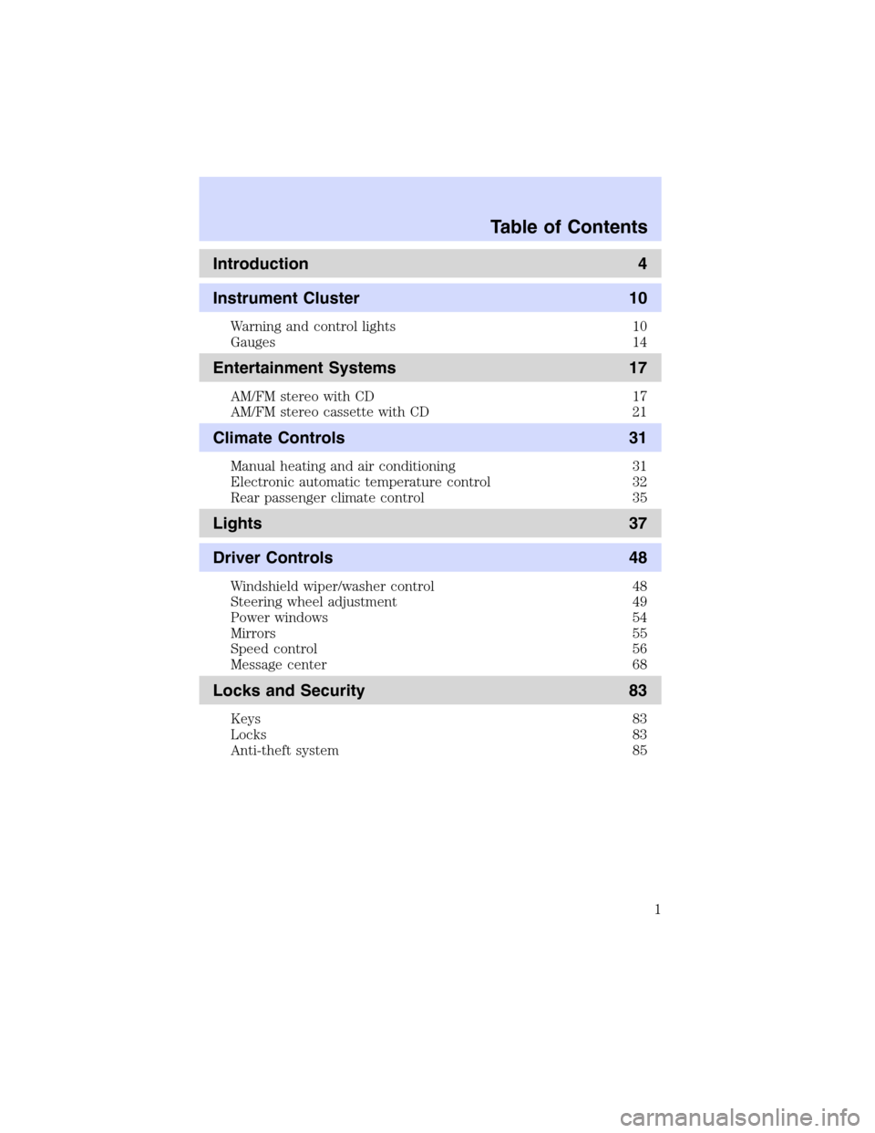
Introduction 4
Instrument Cluster 10
Warning and control lights 10
Gauges 14
Entertainment Systems 17
AM/FM stereo with CD 17
AM/FM stereo cassette with CD 21
Climate Controls 31
Manual heating and air conditioning 31
Electronic automatic temperature control 32
Rear passenger climate control 35
Lights 37
Driver Controls 48
Windshield wiper/washer control 48
Steering wheel adjustment 49
Power windows 54
Mirrors 55
Speed control 56
Message center 68
Locks and Security 83
Keys 83
Locks 83
Anti-theft system 85
Table of Contents
Table of Contents
1
Page 52 of 264

Installing a garage door opener (if equipped)
The storage compartment can be converted to accommodate a variety of
aftermarket garage door openers:
•Place the Velcro hook onto the
side of the aftermarket
transmitter opposite of the
button.
•Place the transmitter into storage
compartment, button down.
•Place the provided height
adaptors onto the back of the
door as needed.
•Close the door.
•Press the depression in the door
to activate the transmitter.
Automatic dimming rear view mirror
The automatic dimming mirror is
equipped with an automatic
dimming feature. This feature will
change from the normal state to the
non-glare“active”state when bright
lights (glare) reach the mirror.
When the mirror detects bright light from behind, it will adjust
automatically to minimize glare.
The mirror will automatically return to the normal high reflective state
whenever the vehicle is placed in R (Reverse) (when the mirror is in the
ON position). This helps to ensure a bright clear view in the mirror when
backing up.
OFF AUTO
Driver Controls
52
Page 53 of 264

Illuminated visor mirror
To turn on the visor mirror lamps,
lift the mirror cover.
AUXILIARY POWER POINT
Power outlets are designed for
accessory plugs only. Do not
hang any type of accessory or
accessory bracket from the plug.
Improper use of the power
outlet can cause damage not
covered by your warranty.
Do not plug optional electrical
accessories into the cigarette lighter. Use the power point.
Do not use the power point for operating the cigarette lighter element.
The Maximum power each power point can supply depends on the fuse
rating. For example: a 20A fuse should supply a maximum of 240 Watts,
a 15A fuse should supply a maximum of 180 Watts. Exceeding these
limits will result in a blown fuse.
Always keep the power point caps closed when not being used.
Driver Controls
53
Page 55 of 264

Window lock
The window lock feature allows only
the driver to operate the power
windows.
To lock out all the window controls
except for the driver’s press the left
side of the control. Press the right
side to restore the window controls.
Accessory delay
With accessory delay, the window switches and audio system may be
used for up to ten minutes after the ignition switch is turned to the OFF
position or until any door is opened.
POWER SIDE VIEW MIRRORS
The ignition must be in the ACC or ON position to adjust the power side
view mirrors.
To adjust your mirrors:
1. Rotate the control clockwise to
adjust the right mirror and rotate
the control counterclockwise to
adjust the left mirror.
2. Move the control in the direction
you wish to tilt the mirror.
3. Return to the center position to
lock mirrors in place.
Heated outside mirrors
(if equipped)
Both mirrors are heated
automatically to remove ice, mist
and fog when the rear window
defrost is activated.
Do not remove ice from the
mirrors with a scraper or
attempt to readjust the mirror
glass if it is frozen in place.
These actions could cause damage to the glass and mirrors.
Driver Controls
55
Page 56 of 264

Fold-away mirrors
Pull the side mirrors in carefully
when driving through a narrow
space, like an automatic car wash.
POWER ADJUSTABLE FOOT PEDALS
The accelerator and brake pedal
should only be adjusted when the
vehicle is stopped and the gearshift
lever is in the P(Park) position.
Press and hold the rocker control to
adjust accelerator and brake pedal
toward you or away from you.
The adjustment allows for approximately 76 mm (3 inches) of maximum
travel.
Never adjust the accelerator and brake pedal with feet on the
pedals while the vehicle is moving.
SPEED CONTROL (IF EQUIPPED)
With speed control set, you can maintain a speed of 48 km/h (30 mph)
or more without keeping your foot on the accelerator pedal. Speed
control does not work at speeds below 48 km/h (30 mph).
Do not use the speed control in heavy traffic or on roads that
are winding, slippery or unpaved.
Driver Controls
56
Page 67 of 264

3. Locate compass sensor mounted
at base of mirror.
4. Press the button on the top of
the compass module until ZONE
appears in the instrument cluster
display.
5. Release pressure on the button and then slowly press it down again.
6. Continue to press until ZONE
appears in the instrument cluster
display, then release. The display
should show the current zone
number.
7. Press until the desired zone
number appears. The display will flash and then return to normal
operation. The zone is now updated.
Compass calibration adjustment
Perform this adjustment in an open area free from steel structures and
high voltage lines:
For optimum calibration, turn off all electrical accessories (heater/air
conditioning, wipers, etc.) and make sure all vehicle doors are shut.
1. Start the vehicle.
2. Locate compass sensor mounted at base of mirror.
3. Press the button on the top of
the compass module until ZONE
appears in the instrument cluster
display. Continue to hold down until
ZONE disappears and CAL is
displayed (approximately eight
seconds) and release.
4. Drive the vehicle slowly (less than 5 km/h [3 mph]) in circles until
CAL indicator turns off (4–5 complete circles).
5. The compass is now calibrated.
Driver Controls
67
Page 168 of 264

The fuses are coded as follows:
Fuse/Relay
LocationFuse Amp
RatingPassenger Compartment Fuse
Panel Description
1 30A Memory seat module, Driver
power seat
2 20A Moonroof
3 20A Radio, Amplifier, DVD
4 5A Front wiper module
5 15A Flasher relay (Turn, hazards)
6 10A Right horn
7 15A Heated mirrors
8—Not used
9—Not used
10 10A Heated backlight relay coil, A/C
clutch contact
11 20A Heated seats
12—Not used
13 5A Overdrive cancel switch, Flex fuel
sender
14 5A PATS module
15 5A Rear wiper module, Cluster, TPMS
16 5A Power mirror, Manual climate
control, TPMS
17 15A Delayed acc. coil, Battery saver,
Glove compartment lamp, 2nd
row courtesy lamps, Interior
lamps (front)
18 10A Left horn
19 10A RCM
20 5A Driver seat switch, Driver seat
module, BSM, Sunload sensor
21 5A Instrument cluster, Compass,
Flasher coil
22 10A ABS
Roadside Emergencies
168
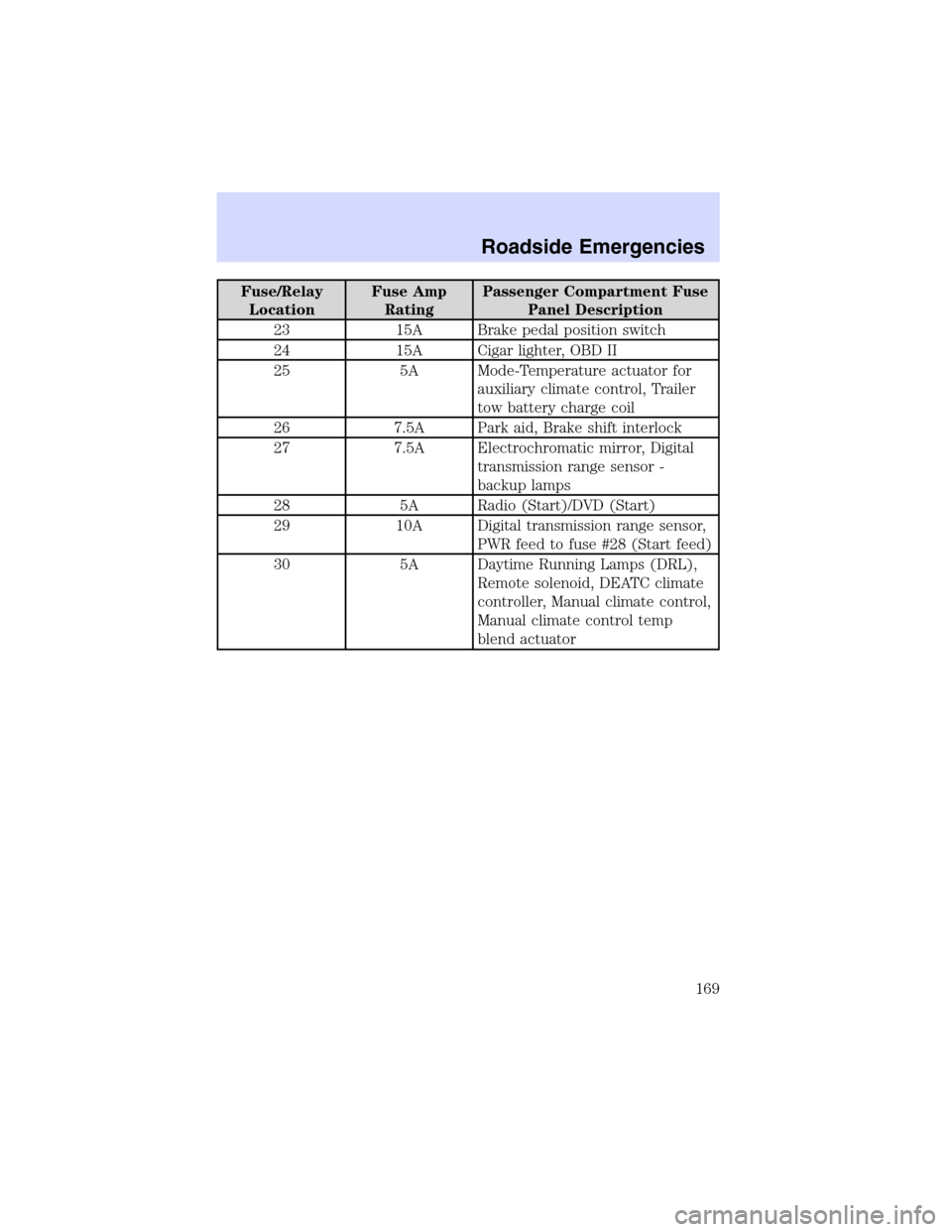
Page 169 of 264

Fuse/Relay
LocationFuse Amp
RatingPassenger Compartment Fuse
Panel Description
23 15A Brake pedal position switch
24 15A Cigar lighter, OBD II
25 5A Mode-Temperature actuator for
auxiliary climate control, Trailer
tow battery charge coil
26 7.5A Park aid, Brake shift interlock
27 7.5A Electrochromatic mirror, Digital
transmission range sensor -
backup lamps
28 5A Radio (Start)/DVD (Start)
29 10A Digital transmission range sensor,
PWR feed to fuse #28 (Start feed)
30 5A Daytime Running Lamps (DRL),
Remote solenoid, DEATC climate
controller, Manual climate control,
Manual climate control temp
blend actuator
Roadside Emergencies
169
Page 200 of 264

WASHING THE EXTERIOR
Wash your vehicle regularly with cool or lukewarm water and a neutral
Ph shampoo, such as Motorcraft Detail Wash (ZC-3–A), which is available
from your dealer.
•Never use strong household detergents or soap, such as dish washing
or laundry liquid. These products can discolor and spot painted
surfaces.
•Never wash a vehicle that is“hot to the touch”or during exposure to
strong, direct sunlight.
•Always use a clean sponge or carwash mitt with plenty of water for
best results.
•Dry the vehicle with a chamois or soft terry cloth towel in order to
eliminate water spotting.
•It is especially important to wash the vehicle regularly during the
winter months, as dirt and road salt are difficult to remove and cause
damage to the vehicle.
•Immediately remove items such as gasoline, diesel fuel, bird droppings
and insect deposits because they can cause damage to the vehicle’s
paintwork and trim over time.
•Remove any exterior accessories, such as antennas, before entering a
car wash.
•Suntan lotions and insect repellents can damage any painted
surface; if these substances come in contact with your vehicle,
wash off as soon as possible.
•If your vehicle is equipped with running boards, do not use
rubber, plastic and vinyl protectant products on the running
board surface, as the area may become slippery.
WAXING
Applying a polymer paint sealant to your vehicle every six months will
assist in reducing minor scratches and paint damage.
•Wash the vehicle first.
•Do not use waxes that contain abrasives.
•Do not allow paint sealant to come in contact with any non-body
(low-gloss black) colored trim, such as grained door handles, roof
racks, bumpers, side moldings, mirror housings or the windshield cowl
area. The paint sealant will“gray”or stain the parts over time.
Cleaning
Cleaning
200
Page 253 of 264

Travel equipment
Ash cup
Cargo organizer
Cargo tray
Chrome wheels
Cellular phone holder
Daytime running lamps
Dog guard
DVD—Rear entertainment system
Engine block heater
Factory luggage rack adaptors (bike and ski)
First aid kit
Fog lamps
Highway safety kit
Hitch step
Interior mirror, electrochromic with compass (with and without
temperature display)
Luggage/Cargo basket
Moon roof deflector
Original equipment luggage rack cross bars
Raised cross-bars (for luggage rack rails)
Remote start systems
Running boards
Scuff plates
Seatback storage
Smoker’s package
Soft luggage cover
Tail lamp surrounds
Tire step
Trailer hitch (Class III)
Trailer hitch bars and balls
Trailer hitch mounted bike carrier
Accessories
253