ECU Mercury Mountaineer 2004 s Owner's Guide
[x] Cancel search | Manufacturer: MERCURY, Model Year: 2004, Model line: Mountaineer, Model: Mercury Mountaineer 2004Pages: 280, PDF Size: 5.38 MB
Page 126 of 280
Follow all instructions provided by the manufacturer of the
booster seat.
Never put the shoulder belt under a child’s arm or behind the
back because it eliminates the protection for the upper part of
the body and may increase the risk of injury or death in a collision.
Never use pillows, books, or towels to boost a child. They can
slide around and increase the likelihood of injury or death in a
collision.
SAFETY SEATS FOR CHILDREN
Child and infant or child safety seats
Use a safety seat that is recommended for the size and weight of the
child. Carefully follow all of the manufacturer’s instructions with the
safety seat you put in your vehicle. If you do not install and use the
safety seat properly, the child may be injured in a sudden stop or
collision.
When installing a child safety seat:
•Review and follow the information
presented in theAir bag
supplemental restraint system
(SRS) section in this chapter.
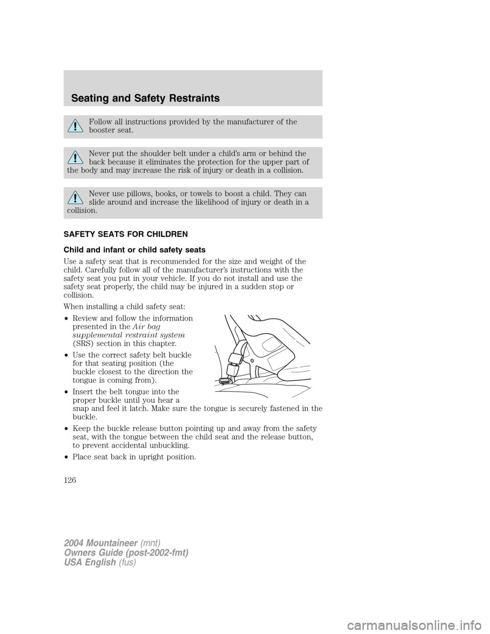
•Use the correct safety belt buckle
for that seating position (the
buckle closest to the direction the
tongue is coming from).
•Insert the belt tongue into the
proper buckle until you hear a
snap and feel it latch. Make sure the tongue is securely fastened in the
buckle.
•Keep the buckle release button pointing up and away from the safety
seat, with the tongue between the child seat and the release button,
to prevent accidental unbuckling.
•Place seat back in upright position.
2004 Mountaineer(mnt)
Owners Guide (post-2002-fmt)
USA English(fus)
Seating and Safety Restraints
126
Page 129 of 280
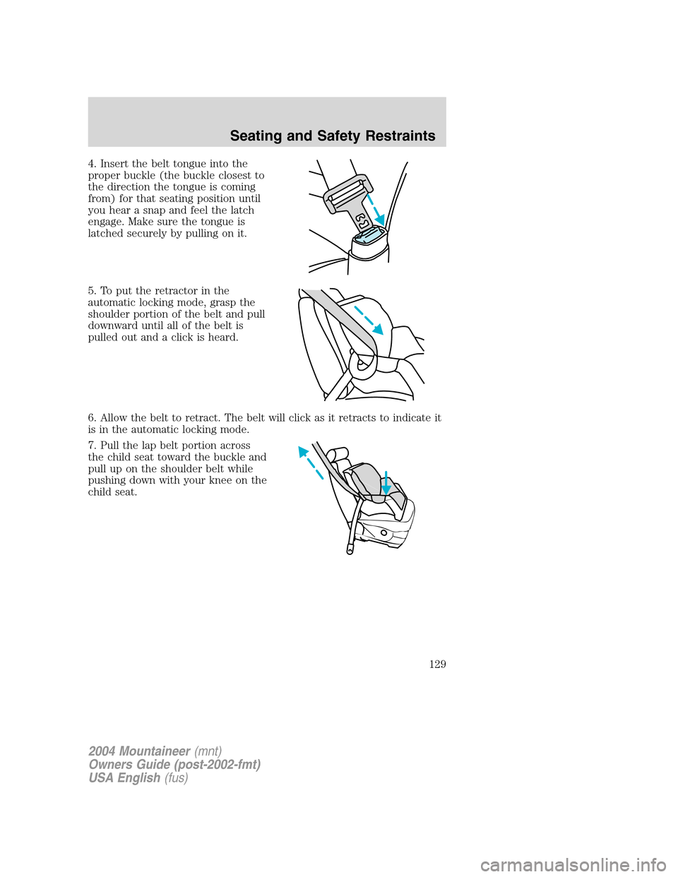
4. Insert the belt tongue into the
proper buckle (the buckle closest to
the direction the tongue is coming
from) for that seating position until
you hear a snap and feel the latch
engage. Make sure the tongue is
latched securely by pulling on it.
5. To put the retractor in the
automatic locking mode, grasp the
shoulder portion of the belt and pull
downward until all of the belt is
pulled out and a click is heard.
6. Allow the belt to retract. The belt will click as it retracts to indicate it
is in the automatic locking mode.
7. Pull the lap belt portion across
the child seat toward the buckle and
pull up on the shoulder belt while
pushing down with your knee on the
child seat.
2004 Mountaineer(mnt)
Owners Guide (post-2002-fmt)
USA English(fus)
Seating and Safety Restraints
129
Page 130 of 280
8. Allow the safety belt to retract to
remove any slack in the belt.
9. Before placing the child in the
seat, forcibly move the seat forward
and back to make sure the seat is
securely held in place. To check
this, grab the seat at the belt path
and attempt to move it side to side
and forward. There should be no
more than one inch of movement for
proper installation.
10. Try to pull the belt out of the retractor to make sure the retractor is
in the automatic locking mode (you should not be able to pull more belt
out). If the retractor is not locked, unbuckle the belt and repeat steps
two through nine.
Check to make sure the child seat is properly secured before each use.
Attaching child safety seats with tether straps
Most new forward-facing child safety seats include a tether strap which
goes over the back of the seat and hooks to an anchoring point. Tether
straps are available as an accessory for many older safety seats. Contact
the manufacturer of your child seat for information about ordering a
tether strap.
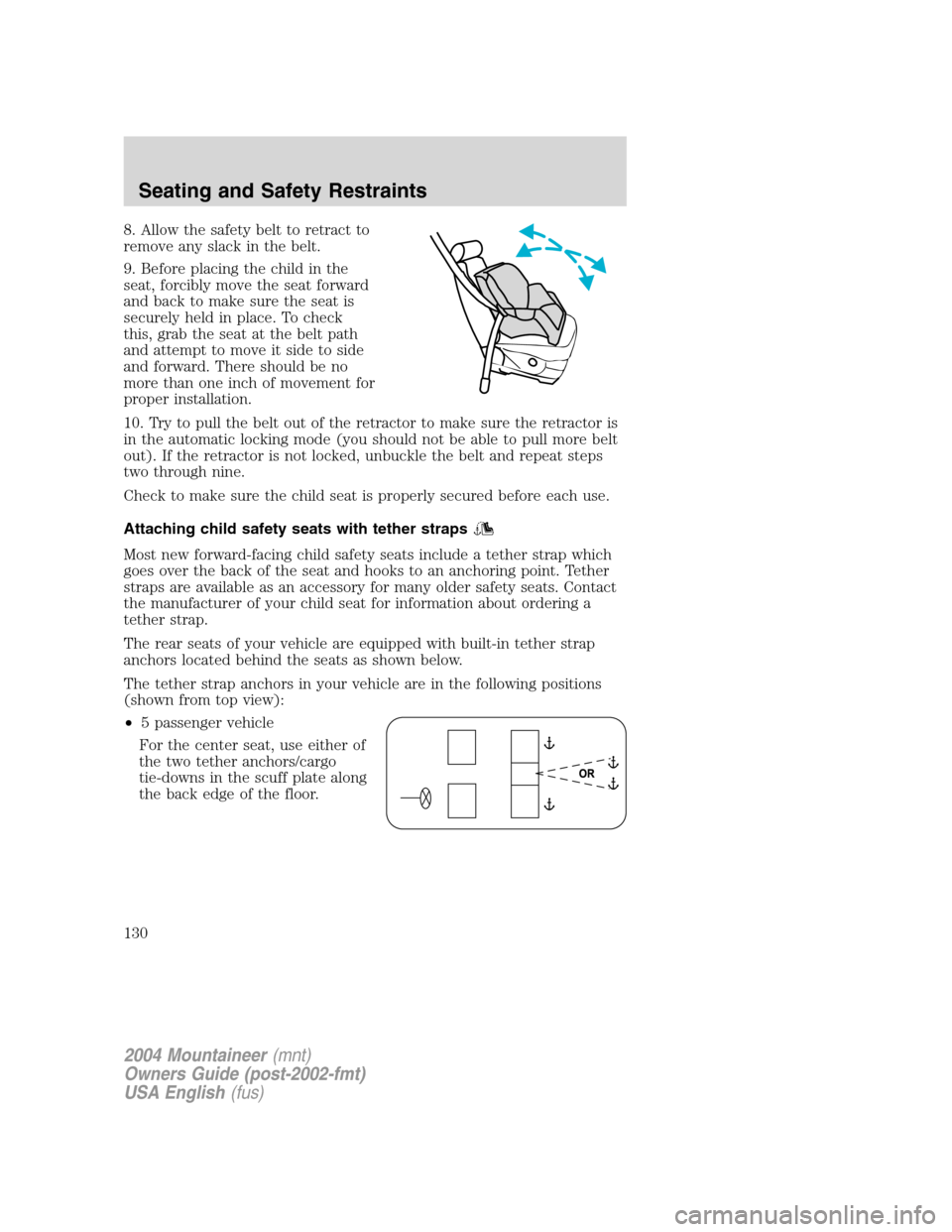
The rear seats of your vehicle are equipped with built-in tether strap
anchors located behind the seats as shown below.
The tether strap anchors in your vehicle are in the following positions
(shown from top view):
•5 passenger vehicle
For the center seat, use either of
the two tether anchors/cargo
tie-downs in the scuff plate along
the back edge of the floor.
2004 Mountaineer(mnt)
Owners Guide (post-2002-fmt)
USA English(fus)
Seating and Safety Restraints
130
Page 140 of 280

Parking brake
Apply the parking brake whenever
the vehicle is parked. To set the
parking brake, press the parking
brake pedal down until the pedal
stops.
The BRAKE warning lamp in the
instrument cluster illuminates and
remains illuminated (when the
ignition is turned ON) until the
parking brake is released.
Always set the parking brake fully and make sure that the
gearshift is securely latched in P (Park).
If the parking brake is fully released, but the brake warning lamp
remains illuminated, the brakes may not be working properly.
See your dealer or a qualified service technician.
The parking brake is not recommended to stop a moving vehicle.
However, if the normal brakes fail, the parking brake can be used to stop
your vehicle in an emergency. Since the parking brake applies only the
rear brakes, the vehicle’s stopping distance will increase greatly and the
handling of your vehicle will be adversely affected.
2004 Mountaineer(mnt)
Owners Guide (post-2002-fmt)
USA English(fus)
Driving
140
Page 147 of 280
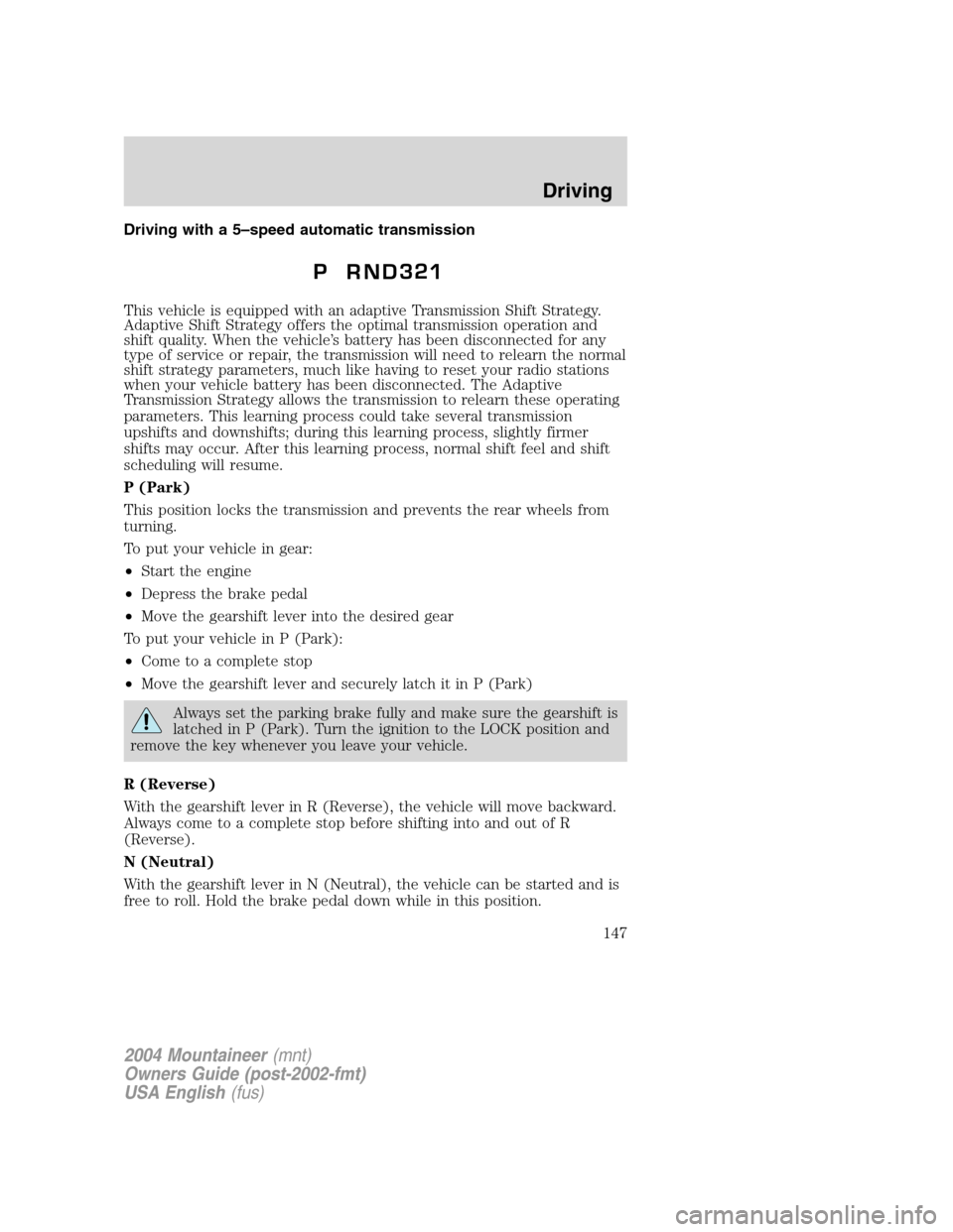
Driving with a 5–speed automatic transmission
This vehicle is equipped with an adaptive Transmission Shift Strategy.
Adaptive Shift Strategy offers the optimal transmission operation and
shift quality. When the vehicle’s battery has been disconnected for any
type of service or repair, the transmission will need to relearn the normal
shift strategy parameters, much like having to reset your radio stations
when your vehicle battery has been disconnected. The Adaptive
Transmission Strategy allows the transmission to relearn these operating
parameters. This learning process could take several transmission
upshifts and downshifts; during this learning process, slightly firmer
shifts may occur. After this learning process, normal shift feel and shift
scheduling will resume.
P (Park)
This position locks the transmission and prevents the rear wheels from
turning.
To put your vehicle in gear:
•Start the engine
•Depress the brake pedal
•Move the gearshift lever into the desired gear
To put your vehicle in P (Park):
•Come to a complete stop
•Move the gearshift lever and securely latch it in P (Park)
Always set the parking brake fully and make sure the gearshift is
latched in P (Park). Turn the ignition to the LOCK position and
remove the key whenever you leave your vehicle.
R (Reverse)
With the gearshift lever in R (Reverse), the vehicle will move backward.
Always come to a complete stop before shifting into and out of R
(Reverse).
N (Neutral)
With the gearshift lever in N (Neutral), the vehicle can be started and is
free to roll. Hold the brake pedal down while in this position.
2004 Mountaineer(mnt)
Owners Guide (post-2002-fmt)
USA English(fus)
Driving
147
Page 178 of 280
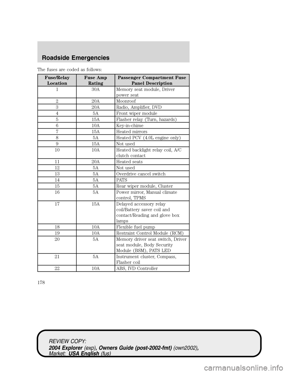
The fuses are coded as follows:
Fuse/Relay
LocationFuse Amp
RatingPassenger Compartment Fuse
Panel Description
1 30A Memory seat module, Driver
power seat
2 20A Moonroof
3 20A Radio, Amplifier, DVD
4 5A Front wiper module
5 15A Flasher relay (Turn, hazards)
6 10A Key-in-chime
7 15A Heated mirrors
8 5A Heated PCV (4.0L engine only)
9 15A Not used
10 10A Heated backlight relay coil, A/C
clutch contact
11 20A Heated seats
12 5A Not used
13 5A Overdrive cancel switch
14 5A PATS
15 5A Rear wiper module, Cluster
16 5A Power mirror, Manual climate
control, TPMS
17 15A Delayed accessory relay
coil/Battery saver coil and
contact/Reading and glove box
lamps
18 10A Flexible fuel pump
19 10A Restraint Control Module (RCM)
20 5A Memory driver seat switch, Driver
seat module, Body Security
Module (BSM), PATS LED
21 5A Instrument cluster, Compass,
Flasher coil
22 10A ABS, IVD Controller
REVIEW COPY:
2004 Explorer(exp), Owners Guide (post-2002-fmt)(own2002),
Market:USA English(fus)
Roadside Emergencies
178
Page 188 of 280
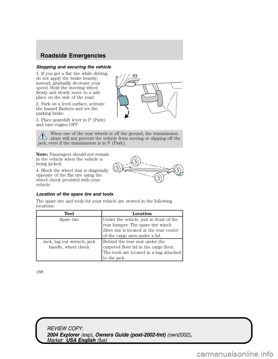
Stopping and securing the vehicle
1. If you get a flat tire while driving,
do not apply the brake heavily;
instead, gradually decrease your
speed. Hold the steering wheel
firmly and slowly move to a safe
place on the side of the road.
2. Park on a level surface, activate
the hazard flashers and set the
parking brake.
3. Place gearshift lever in P (Park)
and turn engine OFF.
When one of the rear wheels is off the ground, the transmission
alone will not prevent the vehicle from moving or slipping off the
jack, even if the transmission is in P (Park).
Note:Passengers should not remain
in the vehicle when the vehicle is
being jacked.
4. Block the wheel that is diagonally
opposite of the flat tire using the
wheel chock provided with your
vehicle.
Location of the spare tire and tools
The spare tire and tools for your vehicle are stowed in the following
locations:
Tool Location
Spare tire Under the vehicle, just in front of the
rear bumper. The spare tire winch
drive nut is located at the rear center
of the cargo area under a lid.
Jack, lug nut wrench, jack
handle, wheel chockBehind the rear seat under the
carpeted floor lid in the cargo floor.
The tools are located in a bag attached
to the jack.
REVIEW COPY:
2004 Explorer(exp), Owners Guide (post-2002-fmt)(own2002),
Market:USA English(fus)
Roadside Emergencies
188
Page 194 of 280
ability, to the point where the ratchet/slip occurs, if possible. The spare
tire carrier will not allow you to overtighten. If the spare tire carrier
ratchets or slips with little effort, take the vehicle to your dealer for
assistance at your earliest convenience.
4. Check that the tire lies flat against the frame and is properly
tightened. Try to push or pull, then turn the tire to be sure it will not
move. Loosen and retighten, if necessary. Failure to properly stow the
spare tire may result in failure of the winch cable and loss of the tire.
5. If your vehicle is equipped with a spare tire lock and key, be sure to
install the spare tire lock into the bumper drive tube with the spare tire
lock key and jack handle.
6. Repeat this tightness check procedure when servicing the spare tire
pressure (every six months, perScheduled Maintenance Guide), or at any
time that the spare tire is disturbed through service of other components.
Re-stowing the jack and tools
1. Unblock the wheels.
2. Stow the wheel ornament (if removed) in a safe location in the vehicle
(such as the glove box or jack stowage compartment) so it will not
become damaged. Re-install the wheel ornament onto the wheel once the
tire is repaired or replaced.
3. Stow the jack and tools in their respective locations, making sure they
are fully secured so they do not rattle when you drive.
Wheel lug nut torque specifications
Retighten the lug nuts to the specified torque at 500 miles (800 km)
after any wheel disturbance (rotation, flat tire, wheel removal, etc.).
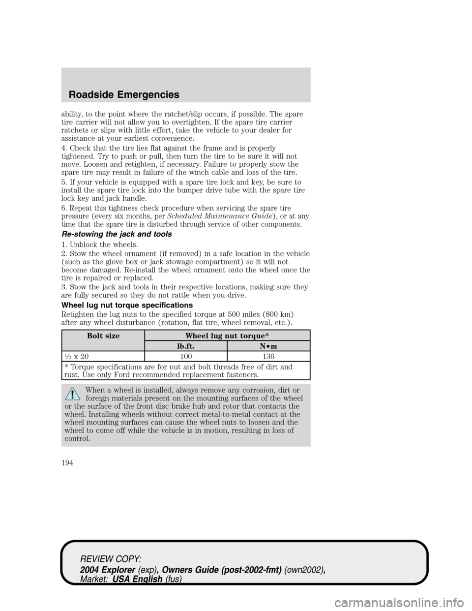
Bolt size Wheel lug nut torque*
lb.ft. N•m
1�2x 20 100 136
* Torque specifications are for nut and bolt threads free of dirt and
rust. Use only Ford recommended replacement fasteners.
When a wheel is installed, always remove any corrosion, dirt or
foreign materials present on the mounting surfaces of the wheel
or the surface of the front disc brake hub and rotor that contacts the
wheel. Installing wheels without correct metal-to-metal contact at the
wheel mounting surfaces can cause the wheel nuts to loosen and the
wheel to come off while the vehicle is in motion, resulting in loss of
control.
REVIEW COPY:
2004 Explorer(exp), Owners Guide (post-2002-fmt)(own2002),
Market:USA English(fus)
Roadside Emergencies
194
Page 207 of 280

IN CALIFORNIA (U.S. ONLY)
California Civil Code Section 1793.2(d) requires that, if a manufacturer
or its representative is unable to repair a motor vehicle to conform to the
vehicle’s applicable express warranty after a reasonable number of
attempts, the manufacturer shall be required to either replace the
vehicle with one substantially identical or repurchase the vehicle and
reimburse the buyer in an amount equal to the actual price paid or
payable by the consumer (less a reasonable allowance for consumer
use). The consumer has the right to choose whether to receive a refund
or replacement vehicle.
California Civil Code Section 1793.22(b) presumes that the manufacturer
has had a reasonable number of attempts to conform the vehicle to its
applicable express warranties if, within the first 18 months of ownership
of a new vehicle or the first 29,000 km (18,000 miles), whichever occurs
first:
1. Two or more repair attempts are made on the same non-conformity
likely to cause death or serious bodily injury OR
2. Four or more repair attempts are made on the same nonconformity (a
defect or condition that substantially impairs the use, value or safety of
the vehicle) OR
3. The vehicle is out of service for repair of nonconformities for a total of
more than 30 calendar days (not necessarily all at one time)
In the case of 1 or 2 above, the consumer must also notify the
manufacturer of the need for the repair of the nonconformity at the
following address:
Ford Motor Company
16800 Executive Plaza Drive
Mail Drop 3NE-B
Dearborn, MI 48126
REVIEW COPY:
2004 Explorer(exp), Owners Guide (post-2002-fmt)(own2002),
Market:USA English(fus)
Customer Assistance
207
Page 220 of 280
ENGINE OIL
Checking the engine oil
Refer to the scheduled maintenance guide for the appropriate intervals
for checking the engine oil.
1. Make sure the vehicle is on level ground.
2. Turn the engine off and wait a few minutes for the oil to drain into the
oil pan.
3. Set the parking brake and ensure the gearshift is securely latched in P
(Park).
4. Open the hood. Protect yourself from engine heat.
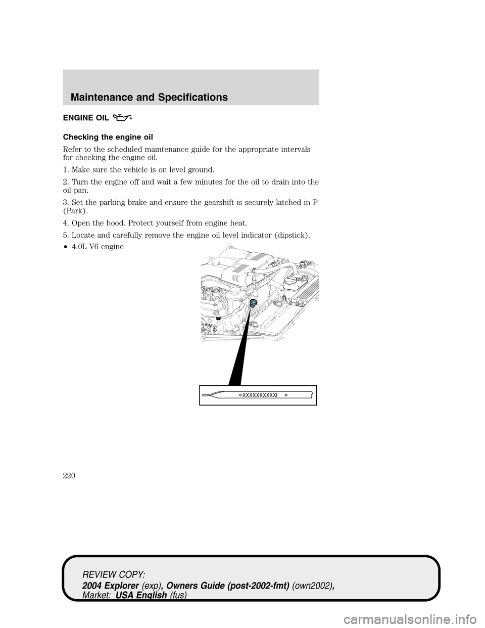
5. Locate and carefully remove the engine oil level indicator (dipstick).
•4.0L V6 engine
REVIEW COPY:
2004 Explorer(exp), Owners Guide (post-2002-fmt)(own2002),
Market:USA English(fus)
Maintenance and Specifications
220