wheel Mercury Mystique 1998 Owner's Manuals
[x] Cancel search | Manufacturer: MERCURY, Model Year: 1998, Model line: Mystique, Model: Mercury Mystique 1998Pages: 196, PDF Size: 1.65 MB
Page 4 of 196

4
Instrumentation
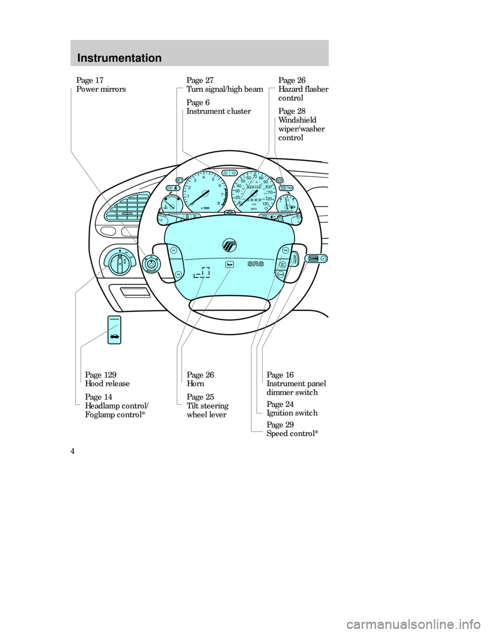
Page 27
Turn signal/high beam
Page 6
Instrument clusterPage 26
Hazard flasher
control
Page 28
Windshield
wiper/washer
control
Page 129
Hood release
Page 14
Headlamp control/
Foglamp control*Page 26
Horn
Page 25
Tilt steering
wheel leverPage 16
Instrument panel
dimmer switch
Page 24
Ignition switch
Page 29
Speed control* Page 17
Power mirrors
CHECK
ENGINEO/D
OFF
Off
Res
Set
Acc
Coast
On
MIRRORS
NORMAL12
03
x 1000
4
5
6
7
8
000123
000010 20 3040506070
80
90
100
110
120
130MPH
20 4060
55
80120 100
140
160
180
200
EF 1
/
2
UNLEADED FUEL ONLY
BRAKE
CDW IIA2Instrum_en MM 5/15/97 7:43 PM Page 4
Page 24 of 196

Controls and features
24STEERING COLUMN
CONTROLS
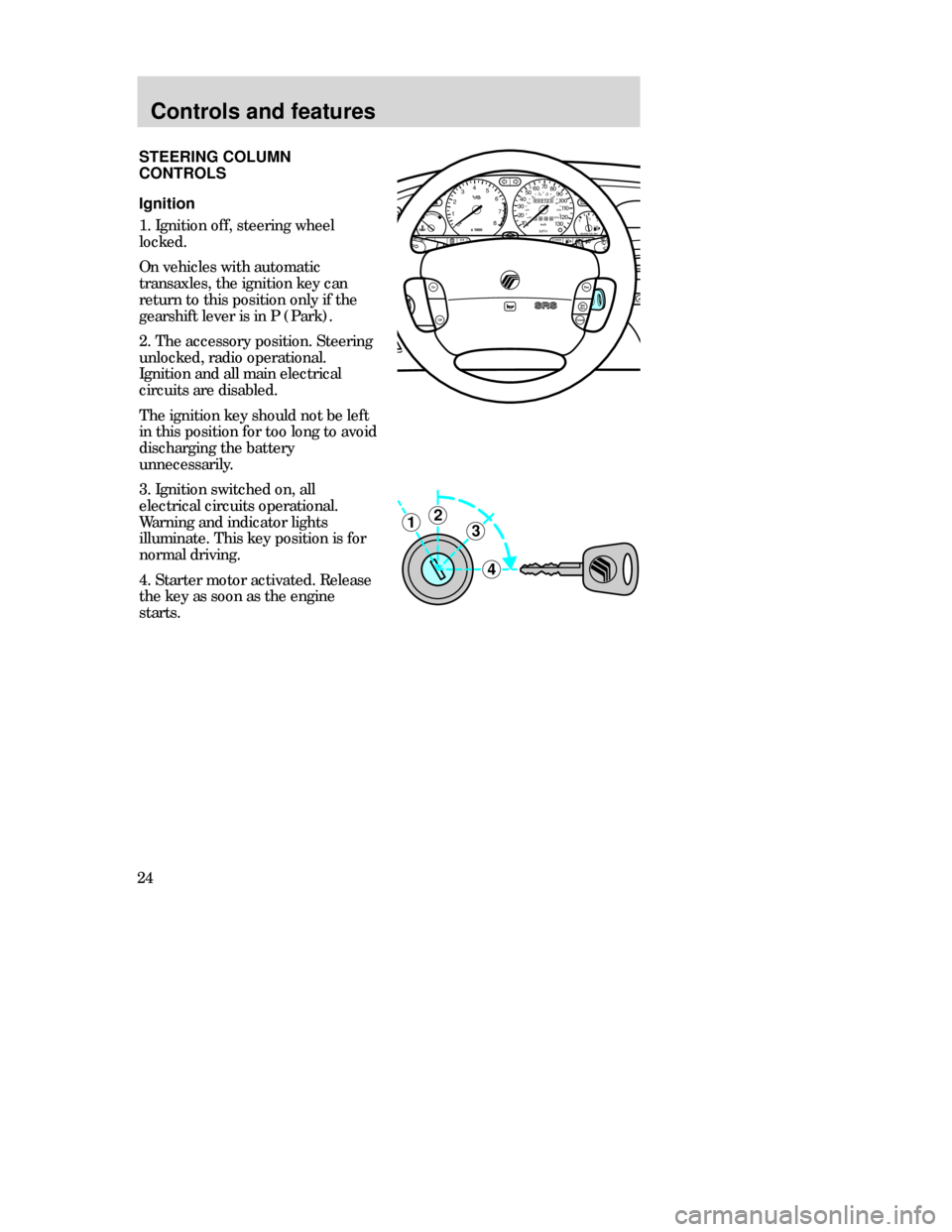
Ignition
1. Ignition off, steering wheel
locked.
On vehicles with automatic
transaxles, the ignition key can
return to this position only if the
gearshift lever is in P (Park).
2. The accessory position. Steering
unlocked, radio operational.
Ignition and all main electrical
circuits are disabled.
The ignition key should not be left
in this position for too long to avoid
discharging the battery
unnecessarily.
3. Ignition switched on, all
electrical circuits operational.
Warning and indicator lights
illuminate. This key position is for
normal driving.
4. Starter motor activated. Release
the key as soon as the engine
starts.
3
4
21
MIRRORS
000123
000010 20 3040506070
80
90
100
110
120
130MPH20 406055
80120 100
140
160
180
200EF 1
/
2UNLEADED FUEL ONLY
12
03x 1000
4
5
6
7
8
NORMALBRAKE
CHECK
ENGINE TRACTION
CONTROLO/D
OFF
Off
Res
Set
AccCoast
On
CDW IIIC3Cont en MM 5/15/97 7:45 PM Page 24
Page 25 of 196

Controls and features
25
POWERAUDIOAM/FM
SCAN
SEEK 312645ANSSIDE1-2EJECTVOLUME
MIRRORSDEF
LO
HIOFFPNL/FLR
PANEL
A/CFLOOR
FLR
DEF
MAX
A/C
000123
000010 20 3040506070
80
90
100
110
120
130MPH20 406055
80120 100
140
160
180
200EF 1
/
2UNLEADED FUEL ONLY
12
03x 1000
4
5
6
7
8
NORMALBRAKE
CHECK
ENGINE TRACTION
CONTROLO/D
OFF
:
I0 20
Off
Res
Set
AccCoast
On
Tilt steering
Pull the locking lever on the
steering column cover up to adjust
the steering column position.
Secure the wheel by pushing the
locking lever down.
Never adjust the steering
wheel while the vehicle is
moving.
CDW IIIC3Cont en MM 5/15/97 7:45 PM Page 25
Page 28 of 196

Controls and features
28
Wipers
Lift the windshield wiper lever to
the desired speed interval.
•Intermittent: push lever up to the
first position.
•Low: push lever up to the second
position.
•High: push lever up to the third
position.
For a single wipe, push the lever
downward.
Windshield wipers and washer
Intermittent wiper control
(if equipped)
Rotate the variable intermittent
wiper control to the desired speed.
1 = Short time interval
6 = Extended time interval
Washer
Pull the lever toward the steering
wheel. The washer operates in
conjunction with the windshield
wipers.
CDW IIIC3Cont en MM 5/15/97 7:45 PM Page 28
Page 84 of 196

Driving
84BRAKES
Your brakes are self-adjusting.
Refer to the “Service Guide” for
maintenance intervals.
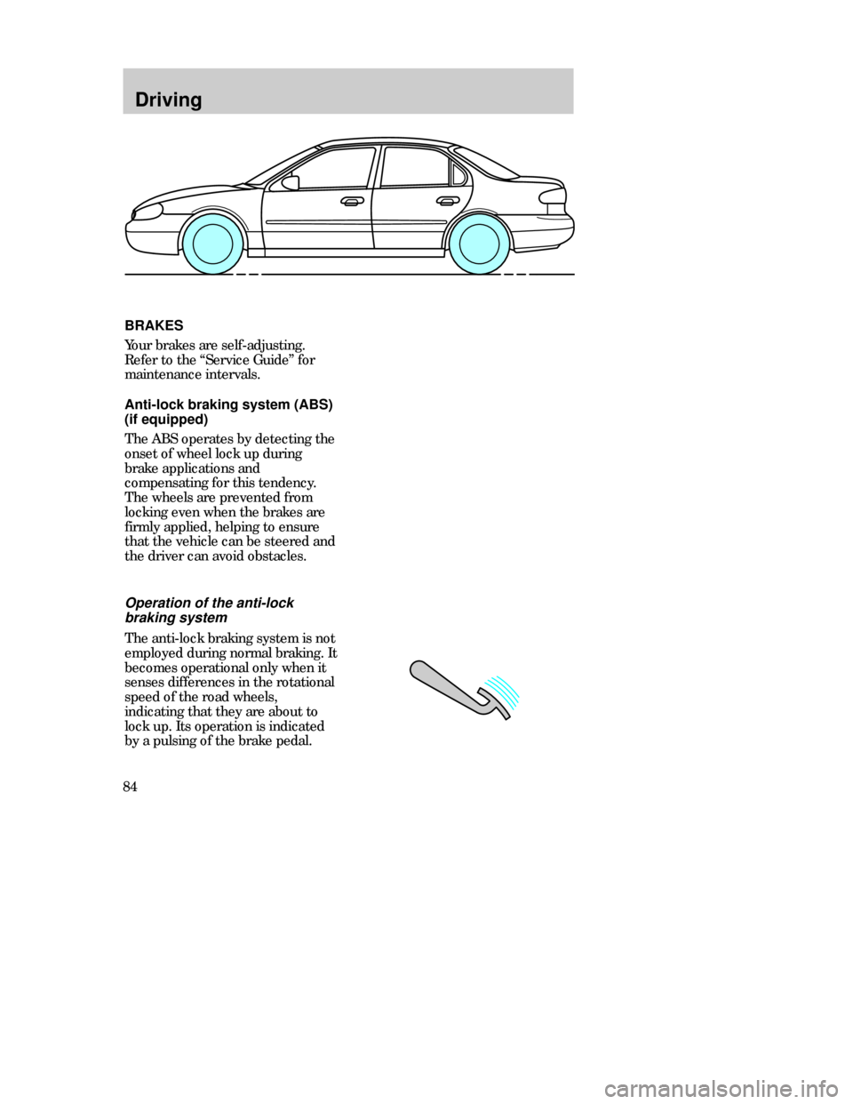
Anti-lock braking system (ABS)
(if equipped)
The ABS operates by detecting the
onset of wheel lock up during
brake applications and
compensating for this tendency.
The wheels are prevented from
locking even when the brakes are
firmly applied, helping to ensure
that the vehicle can be steered and
the driver can avoid obstacles.
Operation of the anti-lock
braking system
The anti-lock braking system is not
employed during normal braking. It
becomes operational only when it
senses differences in the rotational
speed of the road wheels,
indicating that they are about to
lock up. Its operation is indicated
by a pulsing of the brake pedal.
CDW IVB1-10Driving en MM 5/15/97 7:51 PM Page 84
Page 89 of 196

Driving
89 The console-mounted gearshift will
lock when you turn the key to the
lock position. When the gearshift is
in any position except P (Park),
the ignition key cannot be turned
to lock or removed from the
steering column. To remove the
key, the gearshift lever must be in
P (Park).
Once the gearshift is secure in the
desired position, release the brake
pedal and use the accelerator as
necessary.
Driving
Never leave a vehicle
unattended while it is
running.
•P(Park)
Always come to a complete stop
before shifting into P (Park). This
locks the transaxle and prevents
the front wheels from rotating.
•R(Reverse)
The vehicle only moves backward.
Always come to a complete stop
before shifting in or out of R
(Reverse).P=Park. . . . . . . . . . . . . .
R=Reverse. . . . . . . . . . .
N=Neutral. . . . . . . . . . . .
D=Drive: Gear 1 to 4
with overdrive. . . . . .
Gear 1 to 3
with overdrive
cancelled. . . . . . . . . .
2=Gear 2. . . . . . . . . . . .
1=Gear 1. . . . . . . . . . . .
CDW IVB1-10Driving en MM 5/15/97 7:51 PM Page 89
Page 90 of 196

Driving
90
•D (Overdrive)
Note that the vehicle’s gearshift is
console-mounted on the floor. The
transaxle control switch (TCS) is
located on the gearshift handle.
The transaxle control indicator
light (O/D light) is located on the
instrument panel.
Overdrive is not shown on the
display, but is the default mode for
the D gearshift position. This is the
normal driving mode for the best
fuel economy. The transaxle
operates in gears one through four.
The O/D light is off (not
illuminated) during normal vehicle
operation.
Overdrive can be deactivated by
pressing the transaxle control
switch (TCS) located on the
gearshift handle. The O/D OFF
indicator light will illuminate in the
instrument cluster.
•N(Neutral)
The wheels of the transaxle are not
locked. Your vehicle will roll freely,
even on the slightest incline, unless
the parking brake or brakes are on.
CDW IVB1-10Driving en MM 5/15/97 7:51 PM Page 90
Page 116 of 196

Roadside emergencies
116
CHANGING TIRES
Park your vehicle in such a position
that neither the traffic nor you are
hindered or endangered when
changing the tire. Ensure that the
vehicle is on firm, level ground. If
necessary, secure your vehicle
further by blocking the wheels with
chocks.
Activate the hazard lights.
Apply the parking brake and
engage first or reverse gear or, if
the vehicle has an automatic
transaxle, select the P (Park)
position.
If parking on a slope is unavoidable,
secure the wheels with suitable
chocks.
CDW IVC1-6Roads en MM 5/15/97 7:53 PM Page 116
Page 117 of 196

Roadside emergencies
117
80
MAX
km/h
When driving with a temporary
spare tire:
•Do not exceed the maximum
speed of 80 km/h (50 mph) and
only drive the shortest possible
distance.
•Do not exceed the permissible
gross weight of the vehicle.
•Do not install more than one
spare wheel on your vehicle at
any one time.
•Do not use snow chains on this
type of wheel.
•Do not drive through an
automatic car wash.
50
MAX
mph
The temporary spare tire
The vehicle may have a high
pressure temporary spare tire. This
spare is smaller than a regular tire
and is designed for emergency use
only. This tire should be replaced
as soon as possible.
If you use the temporary
spare tire continuously or do
not follow these precautions, the
tire could fail, causing you to lose
control of the vehicle, possibly
injuring yourself or others.
CDW IVC1-6Roads en MM 5/15/97 7:53 PM Page 117
Page 118 of 196

Roadside emergencies
118Spare tire location
The spare tire and tools are located
under the floor cover in the
luggage compartment.
Removing the spare tire and
tools
1. Raise the rear of the floor cover
in the luggage compartment and
fold it forward.
2. Completely unscrew the bolt and
remove the wheel cover panel with
the holder.
3. Remove the wheel cover panel.
4. Lift out the spare wheel.
5. Remove the jack which is located
in the tool pack.
CDW IVC1-6Roads en MM 5/15/97 7:53 PM Page 118