engine Mercury Mystique 2000 s Workshop Manual
[x] Cancel search | Manufacturer: MERCURY, Model Year: 2000, Model line: Mystique, Model: Mercury Mystique 2000Pages: 248, PDF Size: 2.2 MB
Page 144 of 248
Roadside emergencies
144
1
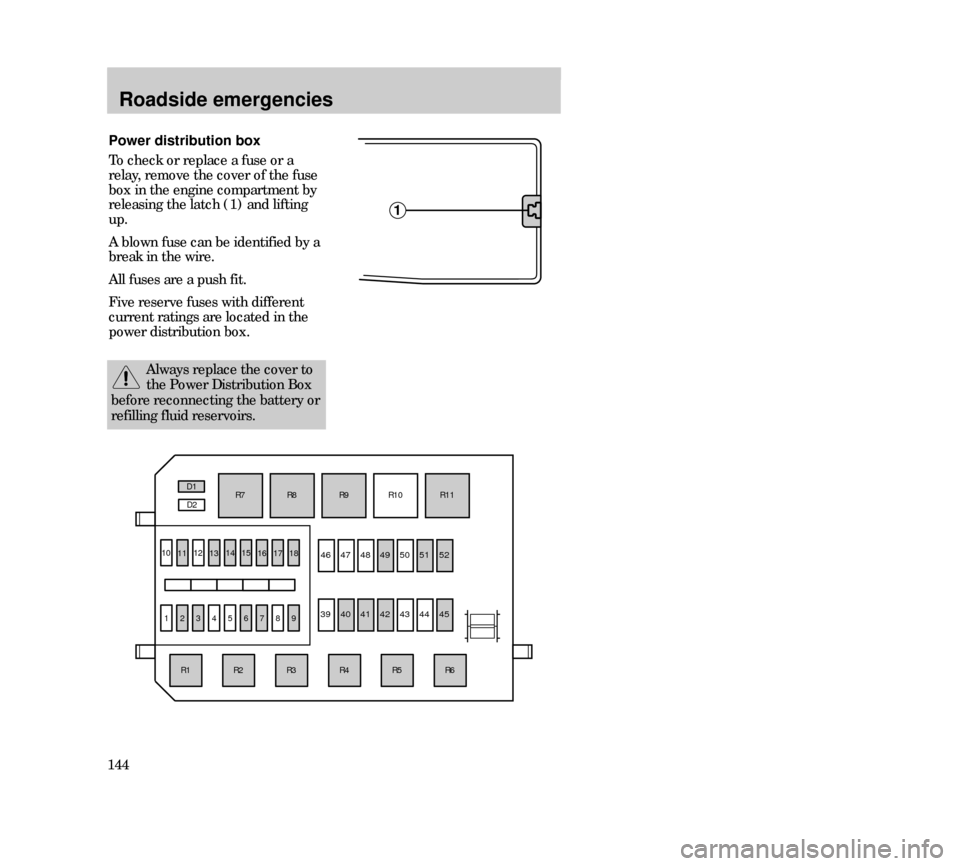
Power distribution box
To check or replace a fuse or a
relay, remove the cover of the fuse
box in the engine compartment by
releasing the latch (1) and lifting
up.
A blown fuse can be identified by a
break in the wire.
All fuses are a push fit.
Five reserve fuses with different
current ratings are located in the
power distribution box.
111213141516
R6R5R4R3R2
10
123456789
R1R7R8
R9R10
R11 D1
D2
17
18
4647
4849 5051 52
394041
424344
45
Always replace the cover to
the Power Distribution Box
before reconnecting the battery or
refilling fluid reservoirs.
23MREen 24.6.99 15:28 Uhr Seite 144
Page 145 of 248
Roadside emergencies
145 Ampere
ratingCircuits protected
1
2
3
4
5
6
7
8
9
10
11
12
13
14
15
16
17
18
39
40
41
42
43
44
45
46
47
48
49
50
51
52—
7.5
20
—
—
3
20
—
15
—
20
—
20
7.5
7.5
7.5
7.5
7.5
—
20*
20*
40*
—
—
60*
—
—
—
60*
—
60*
60*Not used
Alternator
Foglamps
Not used
Not used
EEC ignition module (memory)
Horn and hazard flasher warning system
Not used
Fuel pump
Not used
Ignition, Electronic Engine Control
Not used
HEGO sensor
ABS module
Low beam headlamp (passenger’s side)
Low beam headlamp (driver’s side)
High beam headlamp (passenger’s side)
High beam headlamp (driver’s side)
Not used
Ignition, light switch, central junction box
EEC relay
Central junction box (fuse 37 to blower relay)
Not used
Not used
Ignition
Not used
Not used
Not used
Engine cooling
not used
ABS
Central junction box (central timer module, rear
window defrost relay, fuses 24, 25, 27, 28, 34) Fuse
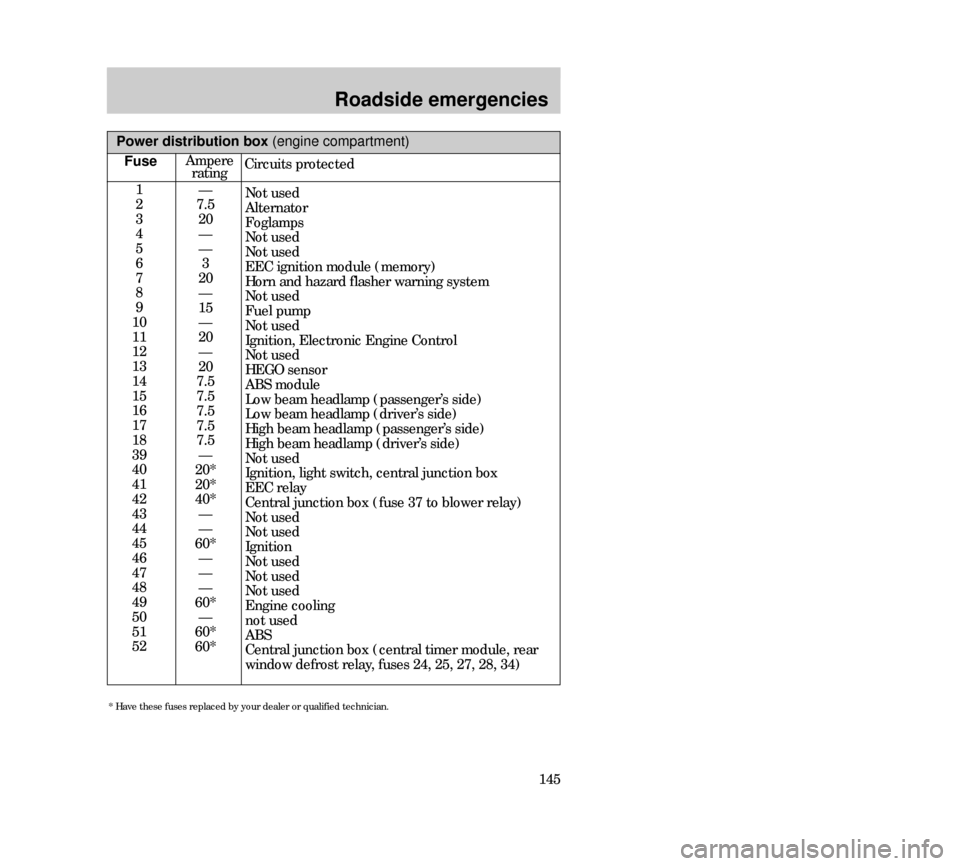
Power distribution box (engine compartment)
* Have these fuses replaced by your dealer or qualified technician.
23MREen 24.6.99 15:28 Uhr Seite 145
Page 146 of 248
Roadside emergencies
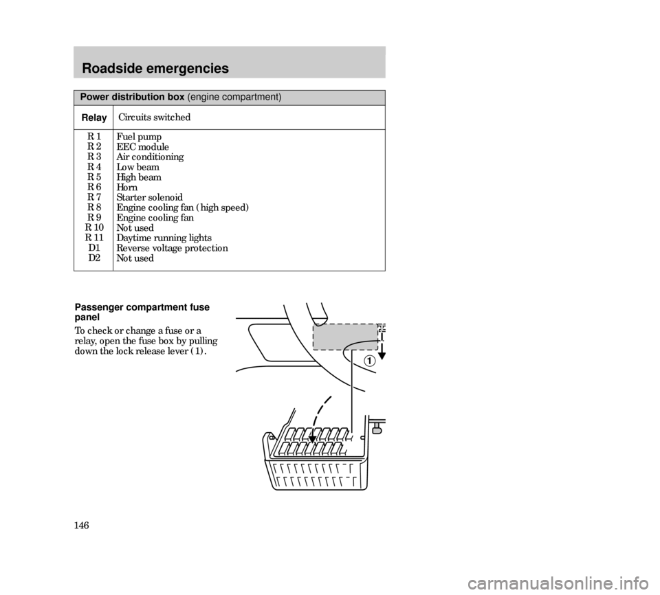
146Passenger compartment fuse
panel
To check or change a fuse or a
relay, open the fuse box by pulling
down the lock release lever (1).
1
Power distribution box (engine compartment)
RelayCircuits switched
R 1
R 2
R 3
R 4
R 5
R 6
R 7
R 8
R 9
R 10
R 11
D1
D2
Fuel pump
EEC module
Air conditioning
Low beam
High beam
Horn
Starter solenoid
Engine cooling fan (high speed)
Engine cooling fan
Not used
Daytime running lights
Reverse voltage protection
Not used
23MREen 24.6.99 15:28 Uhr Seite 146
Page 148 of 248

Roadside emergencies
148
19
20
21
22
23
24
25
26
27
28
29
30
31
32
33
34
35
36
37
38—
C10
40
—
15
15
20
7.5
15
30
30
7.5
7.5
7.5
7.5
7.5
7.5
—
30
—Not used
Wiper motors (circuit breaker)
Power windows
Not used
Backup lamps
Brake lamps
Door locks
Main light
Cigar lighter
Electric seats
Rear window defrost
Engine management system
Instrument panel illumination
Radio
Parking lamps - driver’s side
Interior lighting/electric mirror
adjustment
Parking lamps - passenger’s side
Not used
Heater blower motor
Not used
Passenger compartment fuse panel (below instrument panel)
FuseAmpere
ratingCircuits protected
23MREen 24.6.99 15:28 Uhr Seite 148
Page 155 of 248
Roadside emergencies
155
3. Park the booster vehicle close to
the hood of the disabled vehicle,
making sure the two vehicles do
nottouch. Set the parking brake
on both vehicles and stay clear of
the engine cooling fan and other
moving parts.
4. Check all battery terminals and
remove any excessive corrosion
before you attach the battery
cables. Ensure that vent caps are
tight and level.
5. Turn the heater fan on in both
vehicles to protect from any
electrical surges. Turn all other
accessories off.
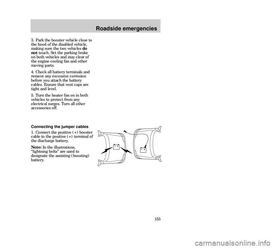
Connecting the jumper cables
1. Connect the positive (+) booster
cable to the positive (+) terminal of
the discharge battery.
Note:In the illustrations,
“lightning bolts” are used to
designate the assisting (boosting)
battery.
23MREen 24.6.99 15:28 Uhr Seite 155
Page 156 of 248
Roadside emergencies
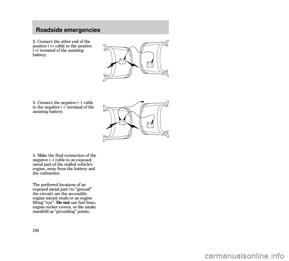
1562. Connect the other end of the
positive (+) cable to the positive
(+) terminal of the assisting
battery.
3. Connect the negative (-) cable
to the negative (-) terminal of the
assisting battery.
4. Make the final connection of the
negative (-) cable to an exposed
metal part of the stalled vehicle’s
engine, away from the battery and
the carburetor.
The preferred locations of an
exposed metal part (to “ground”
the circuit) are the accessible
engine mount studs or an engine
lifting “eye”. Do notuse fuel lines,
engine rocker covers, or the intake
manifold as “grounding” points.
23MREen 24.6.99 15:28 Uhr Seite 156
Page 157 of 248
Roadside emergencies
157
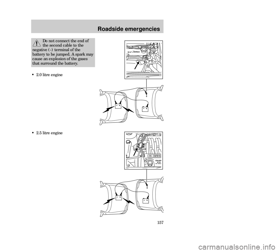
Do not connect the end of
the second cable to the
negative (-) terminal of the
battery to be jumped. A spark may
cause an explosion of the gases
that surround the battery.
• 2.0 litre engine
• 2.5 litre engine
23MREen 24.6.99 15:28 Uhr Seite 157
Page 158 of 248
Roadside emergencies
1585. Be sure that the cables are clear
of fan blades, belts and other
moving parts of both engines.
Jump starting
1. Start the engine of the booster
vehicle and run the engine at a
moderately increased speed.
2. Start the engine of the disabled
vehicle.
3. Once the disabled vehicle has
been started, run both engines for
a further three minutes before
disconnecting the jumper cables.
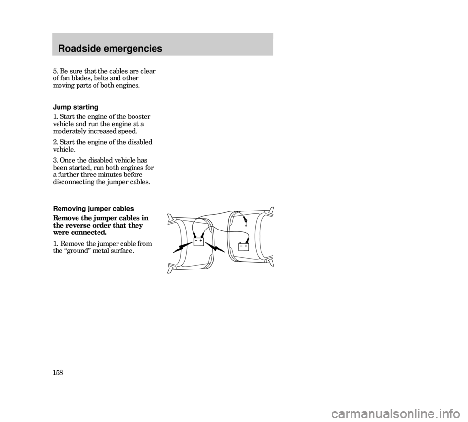
Removing jumper cables
Remove the jumper cables in
the reverse order that they
were connected.
1. Remove the jumper cable from
the “ground” metal surface.
23MREen 24.6.99 15:28 Uhr Seite 158
Page 159 of 248
Roadside emergencies
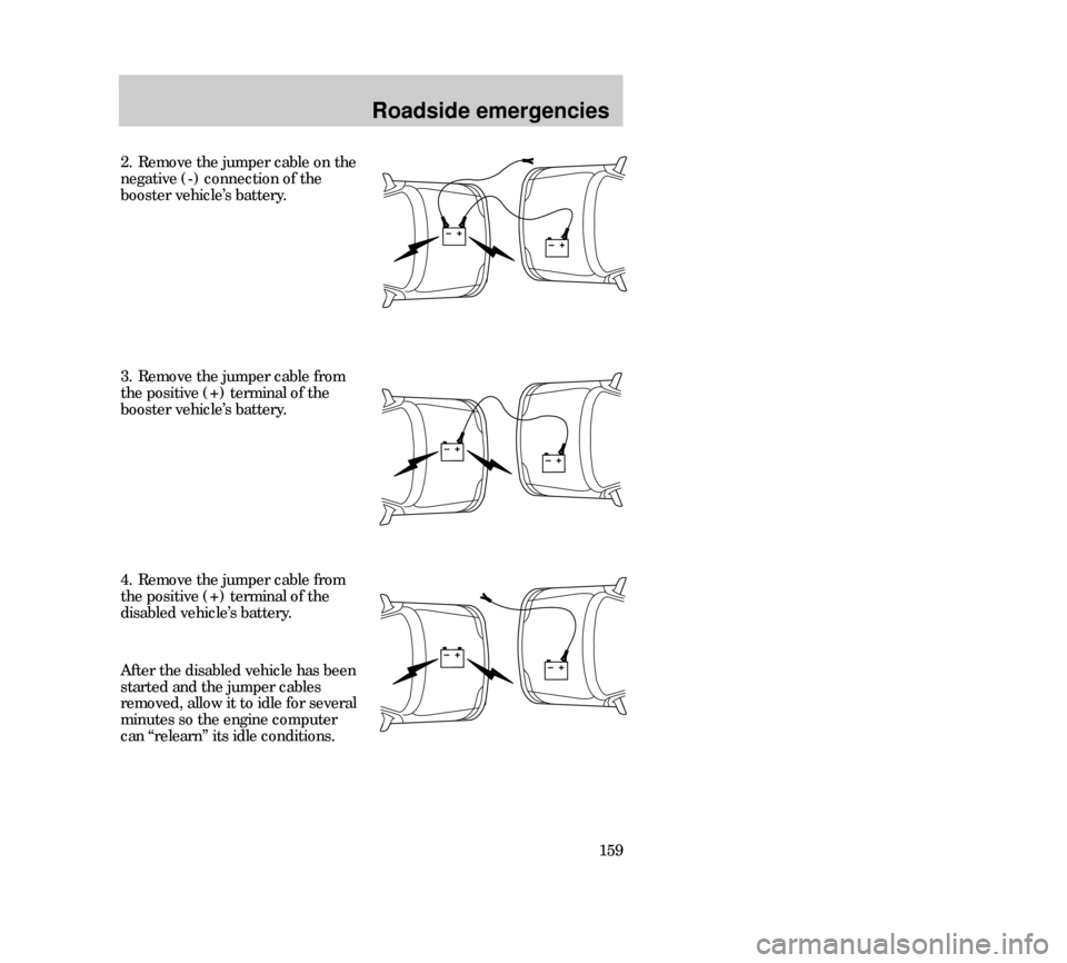
159 2. Remove the jumper cable on the
negative (-) connection of the
booster vehicle’s battery.
4. Remove the jumper cable from
the positive (+) terminal of the
disabled vehicle’s battery. 3. Remove the jumper cable from
the positive (+) terminal of the
booster vehicle’s battery.
After the disabled vehicle has been
started and the jumper cables
removed, allow it to idle for several
minutes so the engine computer
can “relearn” its idle conditions.
23MREen 24.6.99 15:28 Uhr Seite 159
Page 162 of 248

Maintenance and care
162SERVICE RECOMMENDATIONS
• We highlight do-it-yourself items
in the engine compartment for easy
location.
• As possible, we design parts that
can be replaced without tools.
• We provide you with a
maintenance guide and or service
guide which makes tracking routine
service for your vehicle easy.
If your vehicle requires
professional service, your Ford or
Lincoln/Mercury dealership can
provide necessary parts and
service. Check your “Warranty
Guide” to find out which parts and
services are covered.
Use only recommended fuels,
lubricants, fluids and service parts
conforming to specifications.
Motorcraft parts are designed and
built to provide the best
performance in your vehicle.
31MMCen 24.6.99 15:30 Uhr Seite 162