battery Mercury Sable 1997 Owner's Manuals
[x] Cancel search | Manufacturer: MERCURY, Model Year: 1997, Model line: Sable, Model: Mercury Sable 1997Pages: 167, PDF Size: 1.59 MB
Page 9 of 167

Brake system warning
Extinguishes when the
parking brake is
released. Illumination
after releasing the
parking brake indicates low brake fluid level.
Engine oil pressure
When the oil pressure
is below the normal
operating range, this
lamp will illuminate.
The engine oil level being too high or too low could
cause this lamp to illuminate. This lamp will come
on when the ignition is first turned on but then
should turn off. If the lamp stays on, continued
operation will cause severe engine damage.
Charging system
Briefly illuminates
when the ignition is
turned on and the
engine is off. The light
also illuminates when the battery is not charging
properly, requiring electrical system service.
Air bag readiness
Briefly illuminates
when the ignition is
turned on and the
engine is off. If the
light fails to illuminate, continue to flash or remains
on, have the system serviced immediately.
Headlamps on warning chime
Sounds when the headlamps are on, the ignition is
off (and the key is not in the ignition) and the
driver's door is opened.
P!
BRAKE
dno_engine-oil-pressure
com_charging_system.01
dno_srs-light
dno_warning-lights
com_headlamps_chime.01
com_key_chime.01
Instrumentation
9
Page 18 of 167

Changing modes (Temperature conversion)
Press MAX A/C and
the
F-DEF button
at the same time to
switch between
Fahrenheit and Celsius.
If the battery is
disconnected, the
display will revert to
Fahrenheit.
(fan speed)
Once AUTO is pressed, fan speed is adjusted
automatically for existing conditions.
You can override
automatic fan speed (at
any time) by pressing
FAN. The display
window will show FAN
and a series of dots
indicating fan speed. To
return to automatic fan
control, press AUTO.
Manual override controls
The override controls are located on the bottom of
the EATC and allow you to determine where airflow
is directed. To return to full automatic control, press
AUTO.
²MAX A/C - Uses recirculated air to cool the
vehicle. The temperature will display 16ÉC
TEMP
—+OFFAUTOTEMPOUT
SIDEA/C MAXF-DEF
R-DEF
AUTO
VENT
A/C
F—+
TEMP
—+OFFAUTOTEMPOUT
SIDEA/C MAXF-DEF
R-DEF
AUTO
VENT
—+
F—+
TEMP
—+OFFAUTO
TEMPOUT
SIDEA/C MAXF-DEF
R-DEF
AUTO
VENT
F—+
Controls and features
18
Page 43 of 167

Replacing the batteries
The transmitter is powered by two coin type
three-volt lithium batteries. A decrease in operating
range can be caused by:
²battery failure
²weather conditions
²structures around the vehicle
To replace the batteries:
1. Twist a thin coin between the two halves of the
transmitter. DO NOT TAKE THE FRONT PART OF
THE TRANSMITTER APART.
2. Place the positive (+) side of new batteries down.
3. Snap the two halves back together.
Replacing lost transmitters
Take all your vehicle's transmitters to your dealer for
programming if:
²a transmitter is lost or
²you want to purchase additional transmitters (up
to four)
ILLUMINATED ENTRY SYSTEM
The interior lamps
illuminate when:
²the remote entry
system is used to
unlock the door or
sound the personal
alarm.
The system
automatically turns off after 25 seconds or when the
ignition is turned to the START or ACC position.
The inside lights will not turn off if:
²they have been turned on with the dimmer
control or
LOCKUN
LOCK
PANIC
dno_remote-transmitters
com_illuminated_entry.03
Controls and features
43
Page 101 of 167

Fuse/Relay
LocationFuse Amp
RatingDescription
23 5A GEM remote
entry, anti-theft
24 5A Integrated
control panel,
RCC,
speedometer
25 10A OBD II
26 15A Decklid release
27 10A Battery saver
28 15A Brake lamps,
speed control
29 15A Hazard flashers,
multi-function
switch
30 15A High beams,
daytime
running lamps,
instrument
cluster
31 5A Tail lamps
32 10A Integrated
control panel,
climate
controls, heated
mirrors
33 5A Power windows,
lock
illumination
34 - Battery saver
relay
35 - Driver door
unlock relay
Roadside emergencies
101
Page 102 of 167
Fuse/Relay
LocationFuse Amp
RatingDescription
36 - Rear defroster
relay
37 - Interior lamps
relay
38 - One touch
window down
relay
39 - Accessory delay
relay
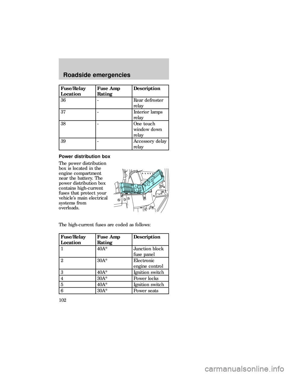
Power distribution box
The power distribution
box is located in the
engine compartment
near the battery. The
power distribution box
contains high-current
fuses that protect your
vehicle's main electrical
systems from
overloads.
The high-current fuses are coded as follows:
Fuse/Relay
LocationFuse Amp
RatingDescription
1 40A* Junction block
fuse panel
2 30A* Electronic
engine control
3 40A* Ignition switch
4 30A* Power locks
5 40A* Ignition switch
6 30A* Power seats
sab_pdb
Roadside emergencies
102
Page 104 of 167
Fuse/Relay
LocationFuse Amp
RatingDescription
28 15A** Electronic
engine control
29 - Washer pump
relay
30 - Horn relay
31 - Autolamp
(headlamps)
32 - Starter relay
33 - Autolamp
(parking lamps)
*Maxi fuses. **Mini fuses
Always disconnect the battery before
servicing high current fuses.
Always replace the cover to the Power
Distribution Box before reconnecting the
battery or refilling fluid reservoirs.
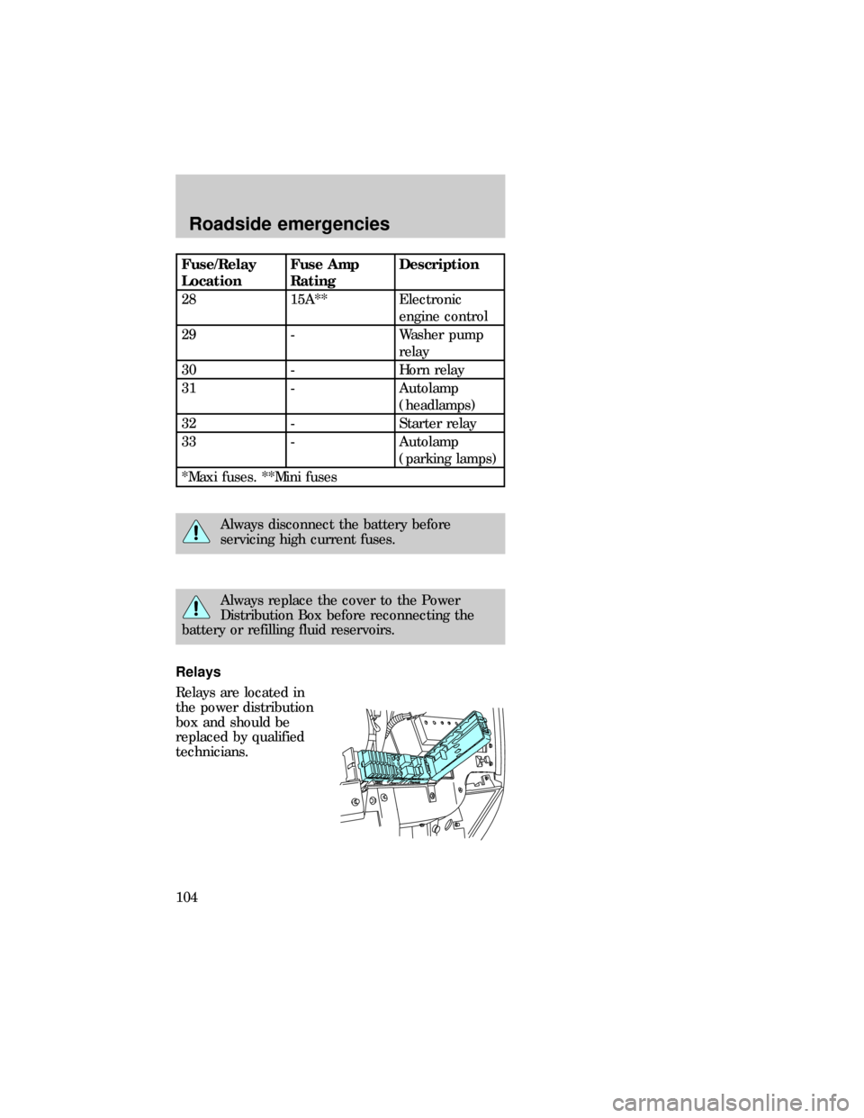
Relays
Relays are located in
the power distribution
box and should be
replaced by qualified
technicians.
dno_relay
dno_flat-tires
Roadside emergencies
104
Page 110 of 167
the key, send the registration card to the
manufacturer (not the dealer) to get a replacement
key. If the lug wrench/lug nut key assembly is lost,
see your nearest Ford or Lincoln/Mercury dealer
who has access to the master set of keys.Do not
use an impact wrench with the anti-theft key.
JUMP STARTING YOUR VEHICLE
The gases around the battery can explode if
exposed to flames, sparks, or lit cigarettes.
An explosion could result in injury or vehicle
damage.
Do not push-start your vehicle. You could
damage the catalytic converter. For further
information, seeJumper Cablesin the Index.
Batteries contain sulfuric acid which burns
skin, eyes, and clothing.
CONNECTING THE JUMPER CABLES
1. Position the vehicles so that they do not touch
one another.
2. Switch off the engine. Switch off any unnecessary
electrical equipment.
com_jump-starting.01
com_connecting_cables.01
Roadside emergencies
110
Page 111 of 167
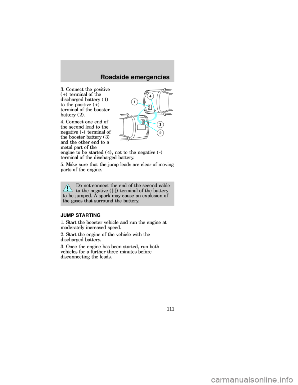
3. Connect the positive
(+) terminal of the
discharged battery (1)
to the positive (+)
terminal of the booster
battery (2).
4. Connect one end of
the second lead to the
negative (-) terminal of
the booster battery (3)
and the other end to a
metal part of the
engine to be started (4), not to the negative (-)
terminal of the discharged battery.
5. Make sure that the jump leads are clear of moving
parts of the engine.
Do not connect the end of the second cable
to the negative ([-]) terminal of the battery
to be jumped. A spark may cause an explosion of
the gases that surround the battery.
JUMP STARTING
1. Start the booster vehicle and run the engine at
moderately increased speed.
2. Start the engine of the vehicle with the
discharged battery.
3. Once the engine has been started, run both
vehicles for a further three minutes before
disconnecting the leads.
+–
+–3
2
1
4
com_jump_starting.01
com_removing_cables.01
Roadside emergencies
111
Page 112 of 167
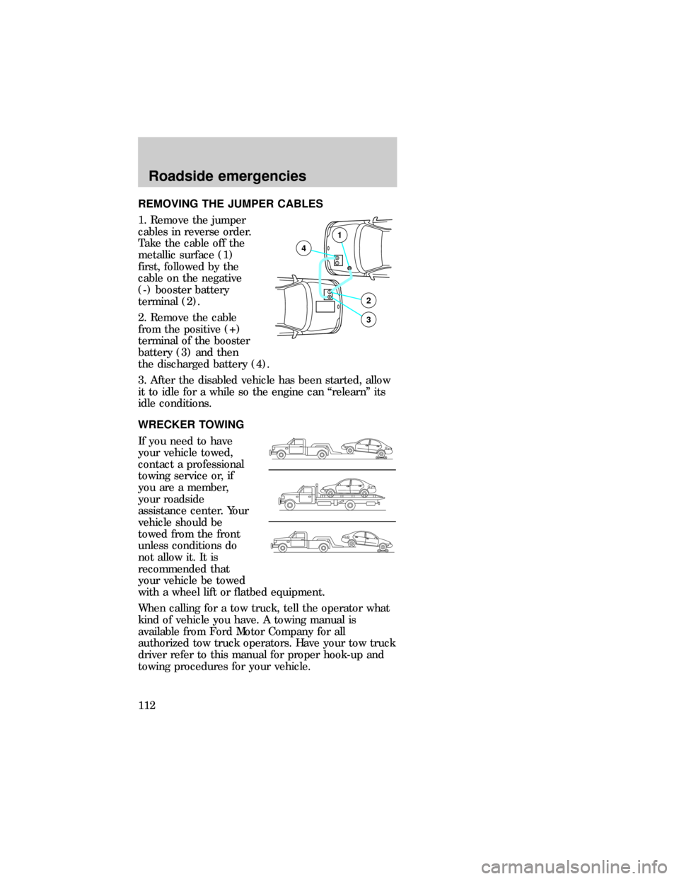
REMOVING THE JUMPER CABLES
1. Remove the jumper
cables in reverse order.
Take the cable off the
metallic surface (1)
first, followed by the
cable on the negative
(-) booster battery
terminal (2).
2. Remove the cable
from the positive (+)
terminal of the booster
battery (3) and then
the discharged battery (4).
3. After the disabled vehicle has been started, allow
it to idle for a while so the engine can ªrelearnº its
idle conditions.
WRECKER TOWING
If you need to have
your vehicle towed,
contact a professional
towing service or, if
you are a member,
your roadside
assistance center. Your
vehicle should be
towed from the front
unless conditions do
not allow it. It is
recommended that
your vehicle be towed
with a wheel lift or flatbed equipment.
When calling for a tow truck, tell the operator what
kind of vehicle you have. A towing manual is
available from Ford Motor Company for all
authorized tow truck operators. Have your tow truck
driver refer to this manual for proper hook-up and
towing procedures for your vehicle.
+–
+–2
3
4
1
dno_towing
dno_towing
Roadside emergencies
112
Page 114 of 167
SERVICE RECOMMENDATIONS
To help you service your vehicle:
²We highlight do-it-yourself items in the engine
compartment for easy location.
²As possible, we design parts that can be replaced
without tools.
²We provide you with a ªService Guideº which
makes tracking routine service for your vehicle
easy.
If your vehicle requires professional service, your
dealership can provide necessary parts and service.
Check your ªWarranty Information Bookletº to find
out which parts and services are covered.
Use only recommended fuels, lubricants, fluids and
service parts conforming to specifications. Motorcraft
parts are designed and built to provide the best
performance in your vehicle.
Precautions when servicing your vehicle
Be especially careful when inspecting or servicing
your vehicle. Here are some general precautions for
your safety:
²Do not work on a hot engine.
The cooling fan is automatic and may come
on at any time. Always disconnect the
negative terminal of the battery before working
near the fan.
²If you must work with the engine running, avoid
wearing loose clothing or jewelry that could get
caught in moving parts. Take precautions with
long hair.
²Do not work on a vehicle with the engine running
in an enclosed space, unless you are sure you
have enough ventilation.
com_service_recommendations.01
com_precautions_servicing.01
Maintenance and care
114