maintenance Mercury Sable 1997 Owner's Manuals
[x] Cancel search | Manufacturer: MERCURY, Model Year: 1997, Model line: Sable, Model: Mercury Sable 1997Pages: 167, PDF Size: 1.59 MB
Page 1 of 167
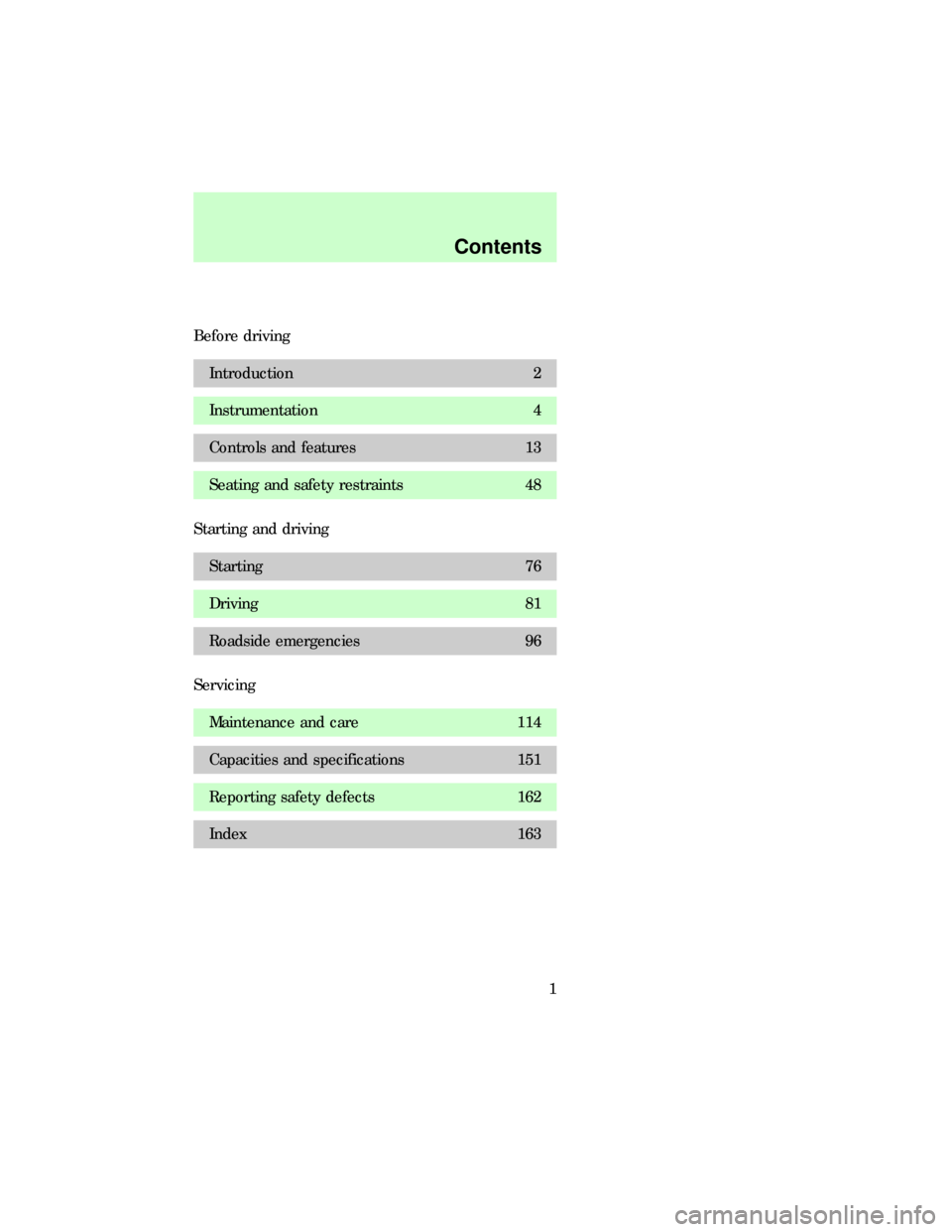
Before driving
Introduction 2
Instrumentation 4
Controls and features 13
Seating and safety restraints 48
Starting and driving
Starting 76
Driving 81
Roadside emergencies 96
Servicing
Maintenance and care 114
Capacities and specifications 151
Reporting safety defects 162
Index 163
Contents
1
Page 11 of 167
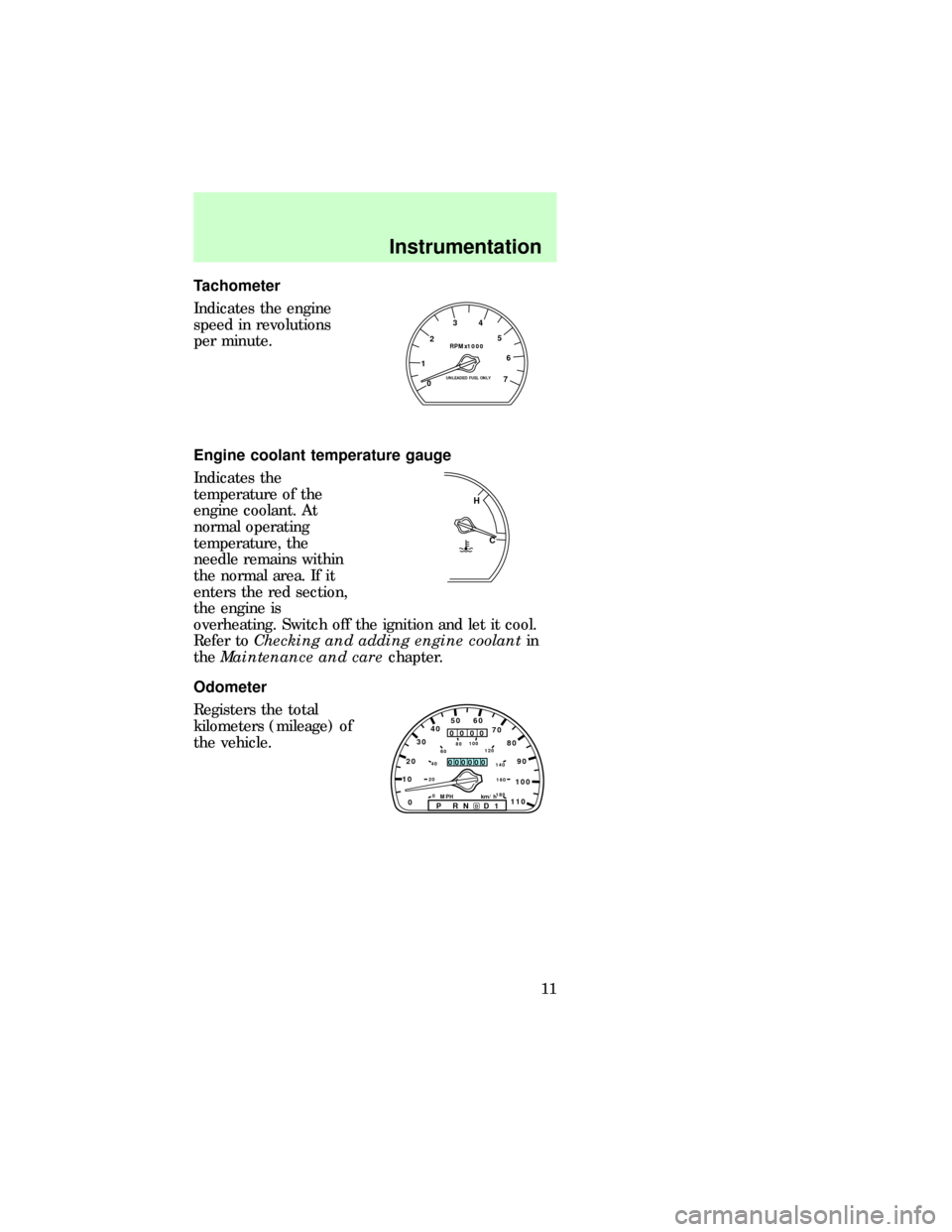
Tachometer
Indicates the engine
speed in revolutions
per minute.
Engine coolant temperature gauge
Indicates the
temperature of the
engine coolant. At
normal operating
temperature, the
needle remains within
the normal area. If it
enters the red section,
the engine is
overheating. Switch off the ignition and let it cool.
Refer toChecking and adding engine coolantin
theMaintenance and carechapter.
Odometer
Registers the total
kilometers (mileage) of
the vehicle.
RPMx1000
0 1234
5
6
7UNLEADED FUEL ONLY
C H
1020304050 60
70
80
90
100
110
0
0 20406080100
120
140
160
180P R N D D 1MPH km/h
00
000
00000
com_coolant_temperature.03
com_odometer.01
com_trip_odometer.01Instrumentation
11
Page 60 of 167
Safety belt maintenance
Check the safety belt systems periodically to make
sure they work properly and are not damaged.
Check the safety belts to make sure there are no
nicks, wears or cuts. All safety belt assemblies,
including retractors, buckles, front seat belt buckle
assemblies (slide bar)(if equipped), shoulder belt
height adjusters (if equipped), child safety seat
tether bracket assemblies (if equipped), and
attaching hardware, should be inspected after a
collision. Ford recommends that all safety belt
assemblies used in vehicles involved in a collision be
replaced. However, if the collision was minor and a
qualified technician finds that the belts do not show
damage and continue to operate properly, they do
not need to be replaced. Safety belt assemblies not
in use during a collision should also be inspected
and replaced if either damage or improper operation
is noted.
Refer toCleaning and maintaining the safety
beltsin theMaintenance and Caresection.
IMPORTANT SUPPLEMENTAL RESTRAINT
SYSTEM (SRS) PRECAUTIONS
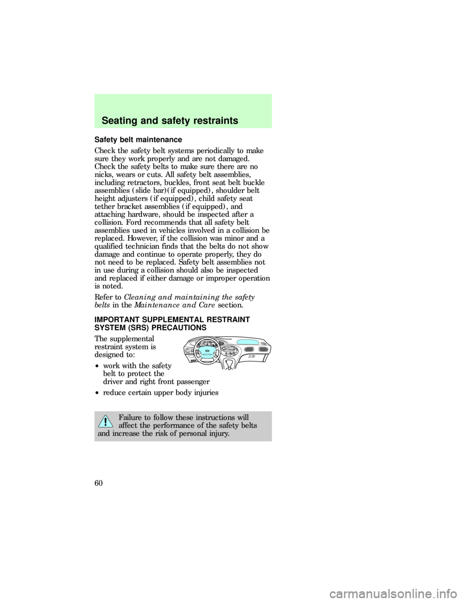
The supplemental
restraint system is
designed to:
²work with the safety
belt to protect the
driver and right front passenger
²reduce certain upper body injuries
Failure to follow these instructions will
affect the performance of the safety belts
and increase the risk of personal injury.
BASSTREBBALFADEREWFFEJECT1234
56wTAPE SIDETAPE
R-DEFTUNESEEKSCAN AM
FMMHLO
HIOFF
A/C
MAX
A/CVENTVOL
PUSH-ONwSTFM 12
AMCBLRFEFC HFUEL DOOR>SERVICE
ENGINE
SOONLOW
COOLANTTHEFT102030405060
70
80
90
100
1202060100
140
180P R N D 2 1MPH km/h0000000000P!
BRAKE+ –110CRUISERPMx1000ABSO/D
OFFREAR
LAMP
OUTPREMIUM UNLEADED
FUEL RECOMMENDED0 1234
5
6
78
dno_belt-maintenance
com_important_precautions.01
Seating and safety restraints
60
Page 63 of 167

If the air bag is inflated,the air bag will
not function again and must be replaced
immediately. If the air bag is not replaced, the
unrepaired area will increase the risk of injury in a
collision.
The SRS consists of:
²driver and passenger air bag modules (which
include the inflators and air bags),
²one or more impact and safing sensors,
²a readiness light and tone
²and the electrical wiring which connects the
components.
The diagnostic module monitors its own internal
circuits and the supplemental air bag electrical
system readiness (including the impact sensors), the
system wiring, the air bag system readiness light, the
air bag back up power and the air bag ignitors.
DETERMINING IF THE SYSTEM IS
OPERATIONAL
The SRS uses a readiness light in the instrument
cluster or a tone to indicate the condition of the
system. Refer to theAir bag readinesssection in
theInstrumentationchapter. Routine maintenance
of the air bag is not required.
A difficulty with the system is indicated by one or
more of the following:
²The readiness light
will either flash or
stay lit.
²The readiness light
will not illuminate immediately after ignition is
turned on.
²A group of five beeps will be heard. The tone
pattern will repeat periodically until the problem
and light are repaired.
com_determing_operational.01
Seating and safety restraints
63
Page 81 of 167
BRAKES
Your brakes are self-adjusting. Refer to the ªService
Guideº for maintenance scheduling.
Anti-lock brake system (ABS) (if equipped)
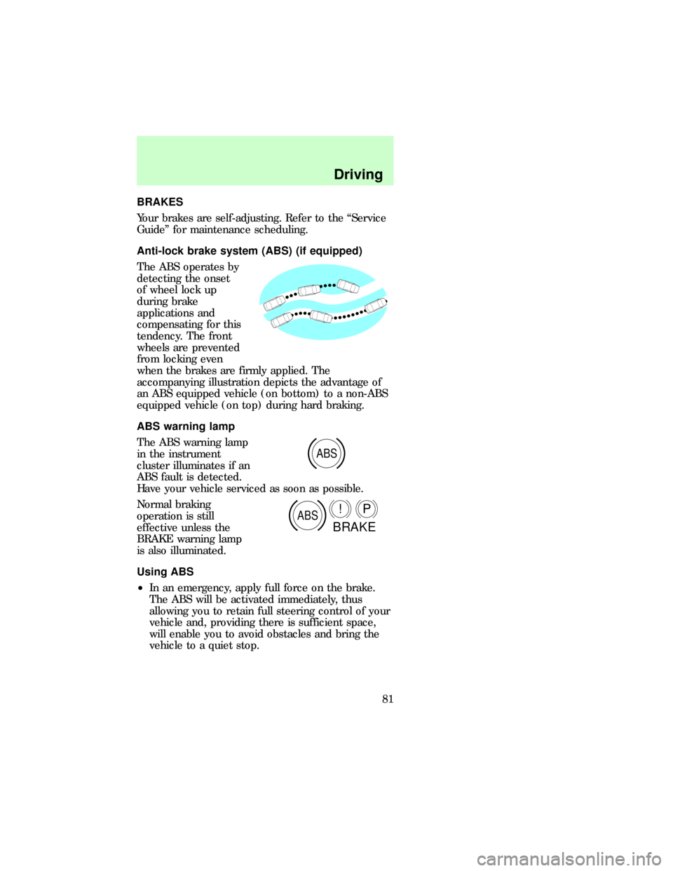
The ABS operates by
detecting the onset
of wheel lock up
during brake
applications and
compensating for this
tendency. The front
wheels are prevented
from locking even
when the brakes are firmly applied. The
accompanying illustration depicts the advantage of
an ABS equipped vehicle (on bottom) to a non-ABS
equipped vehicle (on top) during hard braking.
ABS warning lamp
The ABS warning lamp
in the instrument
cluster illuminates if an
ABS fault is detected.
Have your vehicle serviced as soon as possible.
Normal braking
operation is still
effective unless the
BRAKE warning lamp
is also illuminated.
Using ABS
²In an emergency, apply full force on the brake.
The ABS will be activated immediately, thus
allowing you to retain full steering control of your
vehicle and, providing there is sufficient space,
will enable you to avoid obstacles and bring the
vehicle to a quiet stop.
ABS
ABSP!
BRAKE
com_brakes.01
com_abs.01
dno_ABS-warning-light
com_using_abs.01
Driving
81
Page 95 of 167

FUEL CONSUMPTION
Fuel economy can be improved by avoiding:
²lack of regular, scheduled maintenance
²excessive speed
²rapid acceleration
Driving
95
Page 114 of 167
SERVICE RECOMMENDATIONS
To help you service your vehicle:
²We highlight do-it-yourself items in the engine
compartment for easy location.
²As possible, we design parts that can be replaced
without tools.
²We provide you with a ªService Guideº which
makes tracking routine service for your vehicle
easy.
If your vehicle requires professional service, your
dealership can provide necessary parts and service.
Check your ªWarranty Information Bookletº to find
out which parts and services are covered.
Use only recommended fuels, lubricants, fluids and
service parts conforming to specifications. Motorcraft
parts are designed and built to provide the best
performance in your vehicle.
Precautions when servicing your vehicle
Be especially careful when inspecting or servicing
your vehicle. Here are some general precautions for
your safety:
²Do not work on a hot engine.
The cooling fan is automatic and may come
on at any time. Always disconnect the
negative terminal of the battery before working
near the fan.
²If you must work with the engine running, avoid
wearing loose clothing or jewelry that could get
caught in moving parts. Take precautions with
long hair.
²Do not work on a vehicle with the engine running
in an enclosed space, unless you are sure you
have enough ventilation.
com_service_recommendations.01
com_precautions_servicing.01
Maintenance and care
114
Page 115 of 167
²Keep all lit cigarettes, open flames and other lit
material away from the battery and all fuel related
parts.
If you disconnect the battery, the engine must
ªrelearnº its idle conditions before your vehicle will
drive properly, as explained inBatteryin this
chapter.
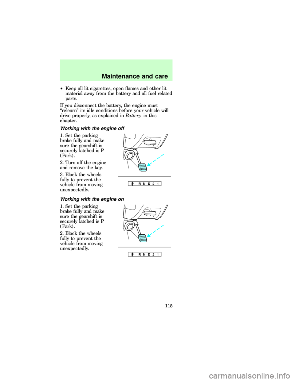
Working with the engine off
1. Set the parking
brake fully and make
sure the gearshift is
securely latched is P
(Park).
2. Turn off the engine
and remove the key.
3. Block the wheels
fully to prevent the
vehicle from moving
unexpectedly.
Working with the engine on
1. Set the parking
brake fully and make
sure the gearshift is
securely latched is P
(Park).
2. Block the wheels
fully to prevent the
vehicle from moving
unexpectedly.
P R N D 2 1
P R N D 2 1
dno_working-off
dno_working-on
dno_open-hood
Maintenance and care
115
Page 116 of 167
Opening the hood
1. Inside the vehicle,
pull the hood release
handle located under
the bottom left corner
of the instrument
panel.
2. Go to the front of the vehicle and release the
auxiliary latch that is located under the front center
of the hood. Lift the hood until the lift cylinders
hold it open.
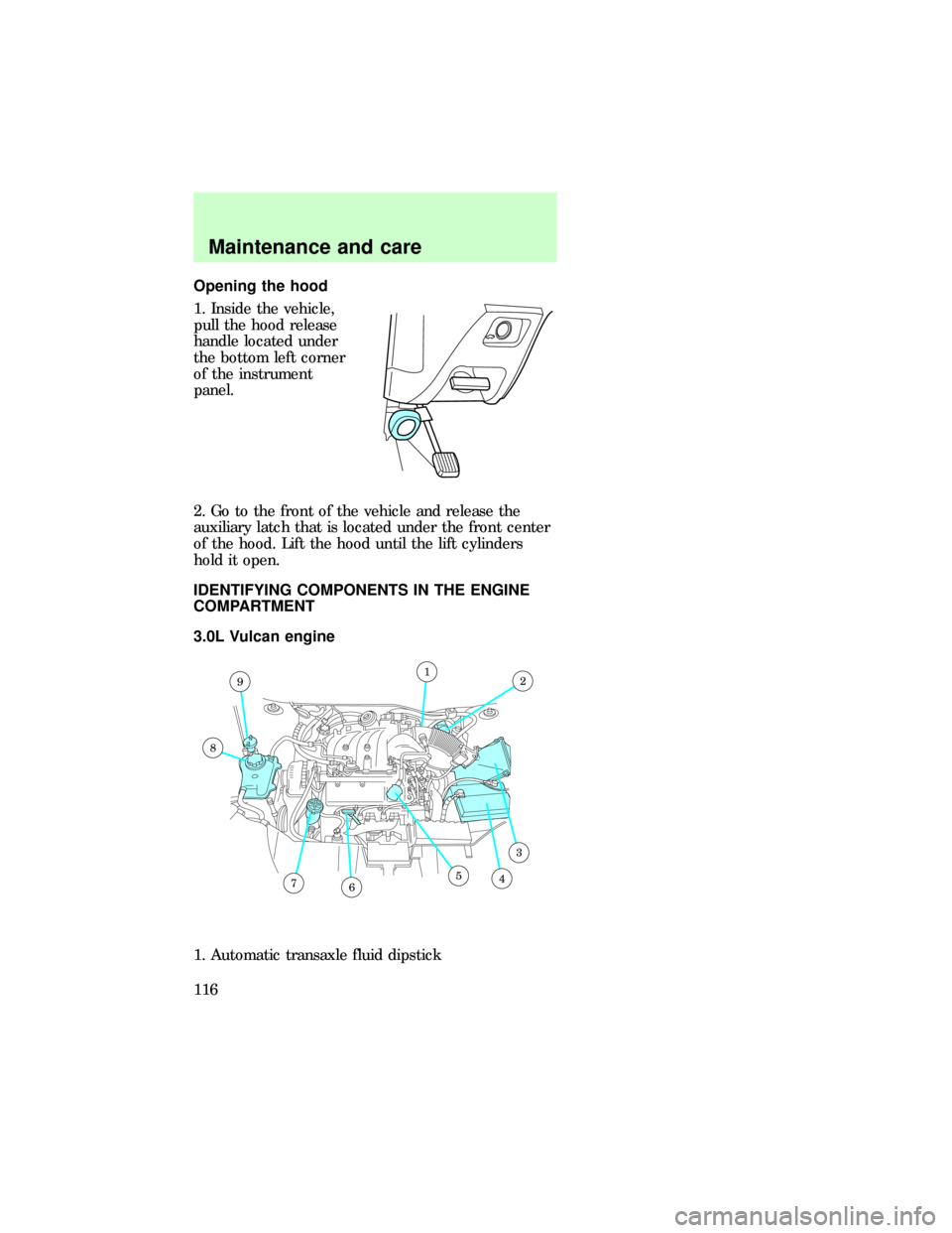
IDENTIFYING COMPONENTS IN THE ENGINE
COMPARTMENT
3.0L Vulcan engine
1. Automatic transaxle fluid dipstick
12
3
4567
8
9
dno_id-engine
dno_vulcan
Maintenance and care
116
Page 117 of 167
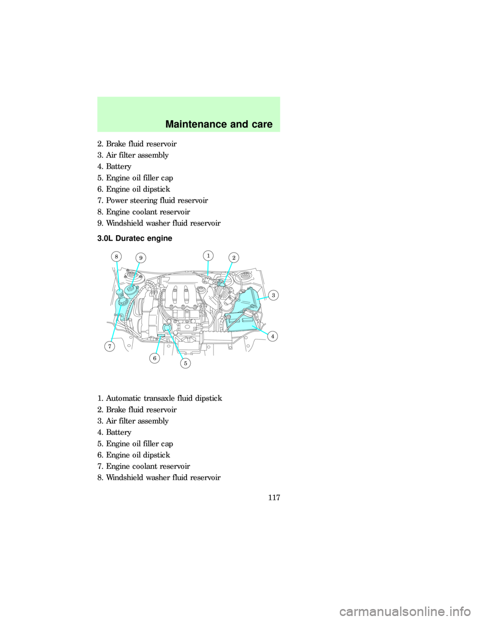
2. Brake fluid reservoir
3. Air filter assembly
4. Battery
5. Engine oil filler cap
6. Engine oil dipstick
7. Power steering fluid reservoir
8. Engine coolant reservoir
9. Windshield washer fluid reservoir
3.0L Duratec engine
1. Automatic transaxle fluid dipstick
2. Brake fluid reservoir
3. Air filter assembly
4. Battery
5. Engine oil filler cap
6. Engine oil dipstick
7. Engine coolant reservoir
8. Windshield washer fluid reservoir
8912
3
4
56
7
dno_duratec
Maintenance and care
117