battery Mercury Sable 1998 Owner's Manuals
[x] Cancel search | Manufacturer: MERCURY, Model Year: 1998, Model line: Sable, Model: Mercury Sable 1998Pages: 190, PDF Size: 1.29 MB
Page 10 of 190

Speed control (if equipped)
This light comes on
when either the
SET/ACCEL or
RESUME controls are
pressed. It turns off
when the speed control OFF control is pressed, the
brake is applied or the ignition is turned to the OFF
position.
Brake system warning
Momentarily illuminates
when the ignition is
turned to the ON
position and the engine
is off. If brake warning lamp does not illuminate at
this time, seek service immediately. Also illuminates
when the parking brake is engaged. Illumination
after releasing the parking brake indicates low brake
fluid level and the brake system should be inspected
immediately.
Engine oil pressure
Illuminates when the
oil pressure falls below
the normal range. Stop
the vehicle as soon as
safely possible and switch off the engine
immediately. Check the oil level and add oil if
needed. Refer toEngine oilin theMaintenance
and Carechapter.
This lamp also illuminates when the ignition is
turned to ON and the engine is off.
Charging system
Illuminates when the
ignition is turned to
the ON position and
the engine is off. The
light also illuminates when the battery is not
CRUISE
ON
P!
BRAKE
Instrumentation
10
Page 45 of 190

Changes or modifications not expressly
approved by the party responsible for
compliance could void the user's authority to
operate the equipment.
Illuminated entry
The interior lamps illuminate when the remote entry
system is used to unlock the door(s) or sound the
personal alarm.
The system automatically turns off after 25 seconds
or when the ignition is turned to the RUN or ACC
position. The dome lamp control (if equipped) must
notbe set to the OFF position for the illuminated
entry system to operate.
The inside lights will not turn off if:
²they have been turned on with the dimmer
control or
²any door is open.
The battery saver will shut off the interior lamps 40
minutes after the ignition has been turned to the
OFF position.
Replacing lost transmitters
Take all your vehicle's
transmitters to your
dealer for
reprogramming if:
²a transmitter is lost
or
²you want to
purchase additional
transmitters (up to four may be programmed).
To reprogram the transmitters, place the key in the
ignition and turn from OFF to ON five times in rapid
succession (within 10 seconds). After doors
lock/unlock, press any control on all transmitters (up
to four). When completed, turn the ignition to OFF.
Controls and features
45
Page 46 of 190

The doors will lock/unlock one last time to confirm
completion of program mode.
All transmitters must be programmed at the same
time.
Replacing the battery
The transmitter is powered by one coin type
three-volt lithium battery CR2032 or equivalent.
Typical operating range will allow you to be up to 10
meters (33 feet) away from your vehicle. A decrease
in operating range can be caused by:
²battery weakness due to time and use
²weather conditions
²nearby radio towers
²structures around the vehicle
²other vehicles parked next to the vehicle
To replace the battery:
1. Twist a thin coin
between the two halves
of the transmitter near
the key ring. DO NOT
TAKE THE FRONT
PART OF THE
TRANSMITTER
APART.
2. Place the positive
(+) side of new battery
in the same orientation.
Refer to the diagram inside the transmitter unit.
3. Snap the two halves back together.
Replacement of the battery willnotcause the
remote transmitter to become deprogrammed from
your vehicle. The remote transmitter should operate
normally after battery replacement.
Controls and features
46
Page 112 of 190

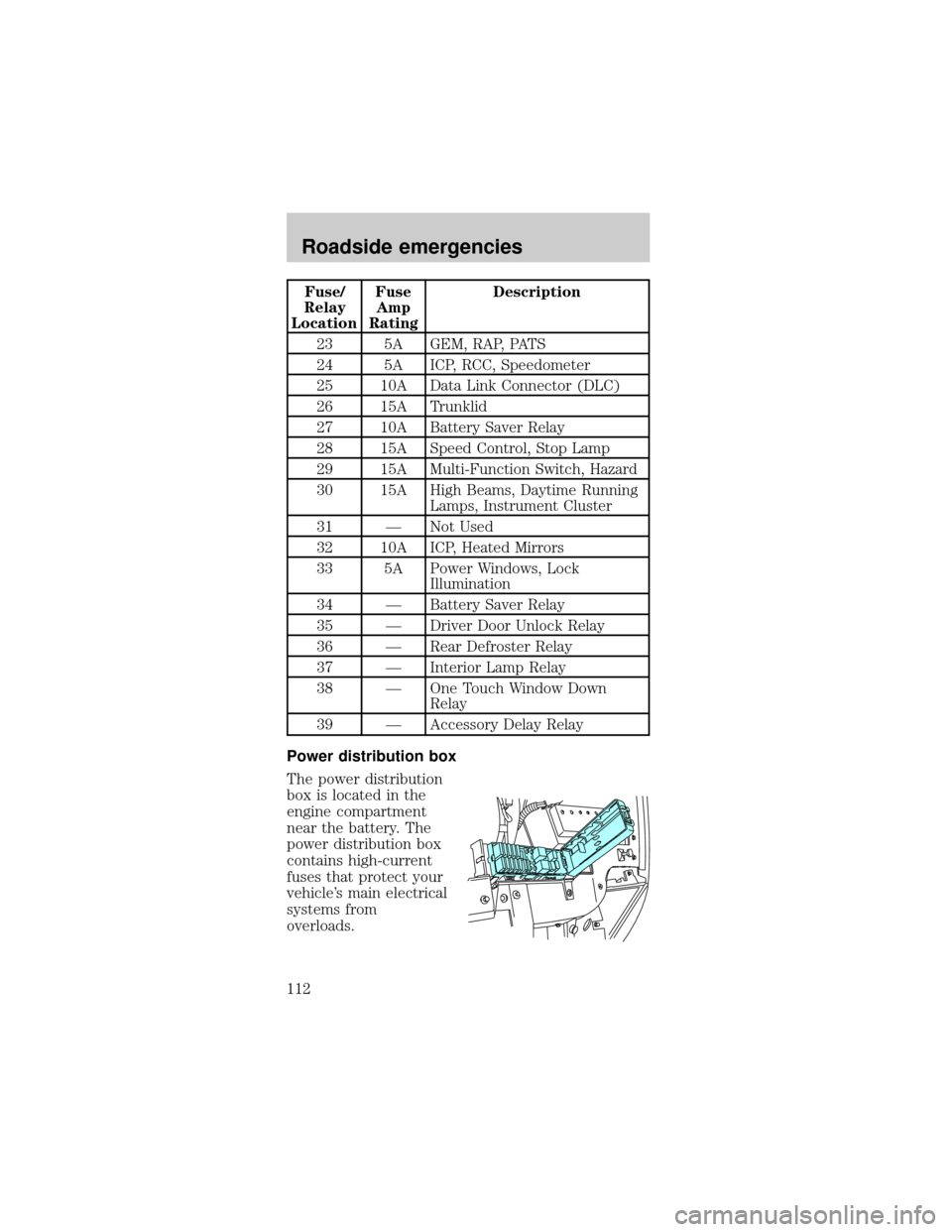
Fuse/
Relay
LocationFuse
Amp
RatingDescription
23 5A GEM, RAP, PATS
24 5A ICP, RCC, Speedometer
25 10A Data Link Connector (DLC)
26 15A Trunklid
27 10A Battery Saver Relay
28 15A Speed Control, Stop Lamp
29 15A Multi-Function Switch, Hazard
30 15A High Beams, Daytime Running
Lamps, Instrument Cluster
31 Ð Not Used
32 10A ICP, Heated Mirrors
33 5A Power Windows, Lock
Illumination
34 Ð Battery Saver Relay
35 Ð Driver Door Unlock Relay
36 Ð Rear Defroster Relay
37 Ð Interior Lamp Relay
38 Ð One Touch Window Down
Relay
39 Ð Accessory Delay Relay
Power distribution box
The power distribution
box is located in the
engine compartment
near the battery. The
power distribution box
contains high-current
fuses that protect your
vehicle's main electrical
systems from
overloads.
Roadside emergencies
112
Page 113 of 190

Always disconnect the battery before
servicing high current fuses.
Always replace the cover to the Power
Distribution Box before reconnecting the
battery or refilling fluid reservoirs.
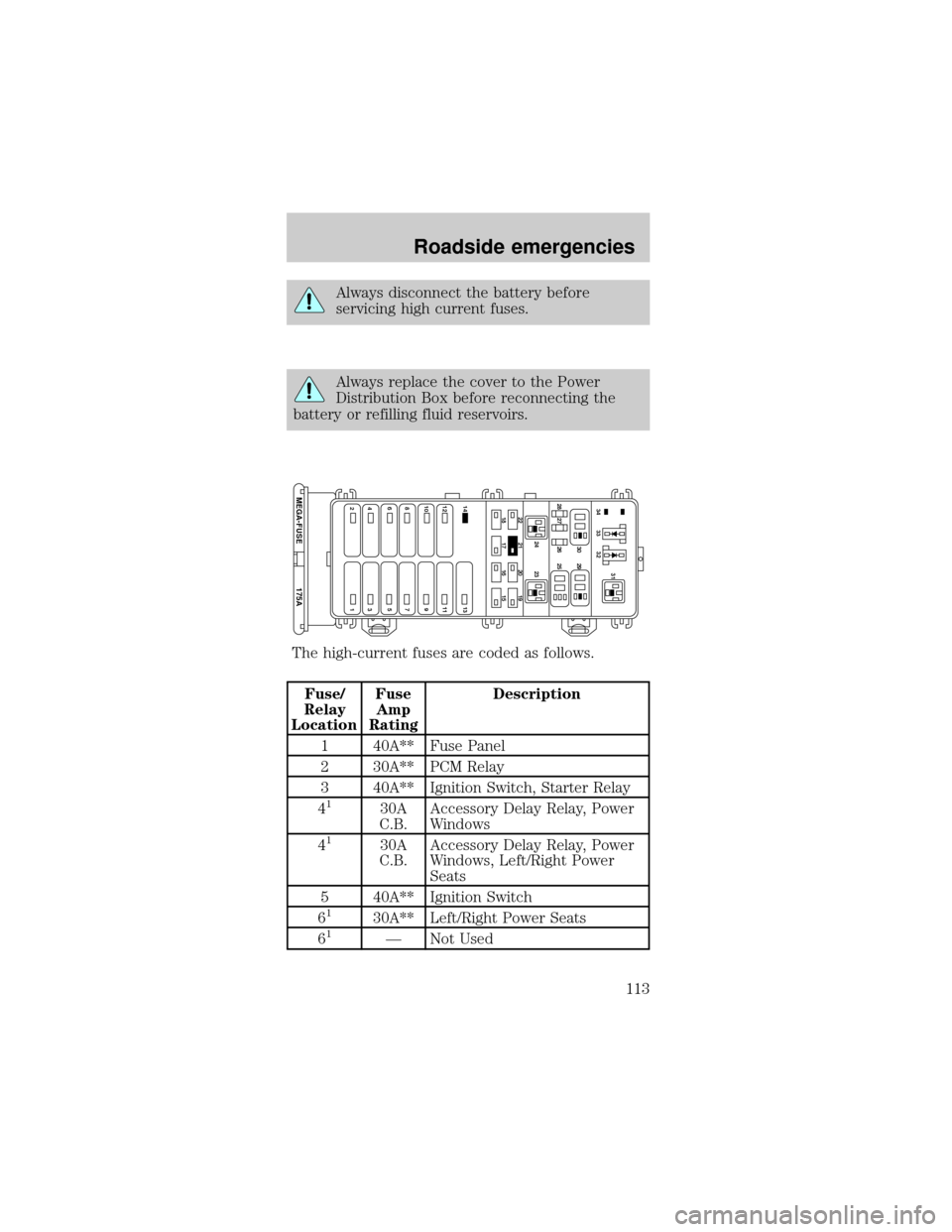
The high-current fuses are coded as follows.
Fuse/
Relay
LocationFuse
Amp
RatingDescription
1 40A** Fuse Panel
2 30A** PCM Relay
3 40A** Ignition Switch, Starter Relay
4
130A
C.B.Accessory Delay Relay, Power
Windows
4
130A
C.B.Accessory Delay Relay, Power
Windows, Left/Right Power
Seats
5 40A** Ignition Switch
6
130A** Left/Right Power Seats
61Ð Not Used
22
14 13
12 11
10 9
87
175A MEGA-FUSE
65
43
2121 24 23 28 27 26 2530 2931
33 3432
20 19
18 17 16 15
Roadside emergencies
113
Page 121 of 190

JUMP STARTING YOUR VEHICLE
The gases around the battery can explode if
exposed to flames, sparks, or lit cigarettes.
An explosion could result in injury or vehicle
damage.
Do not push start your vehicle. You could
damage the catalytic converter.
Batteries contain sulfuric acid which burns
skin, eyes, and clothing.
Preparing your vehicle
1.Use only a 12±volt supply to start your
vehicle.
2. Do not disconnect the battery of the disabled
vehicle as this could damage the vehicle's electrical
system.
3. Park the booster vehicle close to the hood of the
disabled vehicle making sure the two vehiclesdo
nottouch. Set the parking brake on both vehicles
and stay clear of the engine cooling fan and other
moving parts.
4. Check all battery terminals and remove any
excessive corrosion before you attach the battery
cables. Ensure that vent caps are tight and level.
5. Turn the heater fan on in both vehicles to protect
any electrical surges. Turn all other accessories off.
Roadside emergencies
121
Page 122 of 190

Connecting the jumper cables
1. Connect the positive (+) booster cable to the
positive (+) terminal of the discharged battery.
Note:In the illustrations,lightning boltsare used
to designate the assisting (boosting) battery.
2. Connect the other end of the positive (+) cable to
the positive (+) terminal of the assisting battery.
3. Connect the negative (-) cable to the negative (-)
terminal of the assisting battery.
+–+–
+–+–
+–+–
Roadside emergencies
122
Page 123 of 190

4. Make the final connection of the negative (-)
cable to an exposed metal part of the stalled
vehicle's engine, away from the battery and the
carburetor.
The preferred locations of an exposed metal part (to
groundthe circuit) are the alternator mounting
brackets or an engine liftingeye.Do notuse fuel
lines, engine rocker covers or the intake manifold as
groundingpoints.
Do not connect the end of the second cable
to the negative (-) terminal of the battery to
be jumped. A spark may cause an explosion of the
gases that surround the battery.
5. Be sure that the cables are clear of fan blades,
belts and other moving parts of both engines.
+–+–
Roadside emergencies
123
Page 124 of 190

Jump starting
1. Start the engine of the booster vehicle and run
the engine at moderately increased speed.
2. Start the engine of the disabled vehicle.
3. Once the disabled vehicle has been started, run
both engines for a further three minutes before
disconnecting the jumper cables.
Removing the jumper cables
Remove the jumper cables in the reverse order
that they were connected.
1. Remove the jumper cable from thegroundmetal
surface.
2. Remove the jumper cable on the negative (-)
connection of the booster vehicle's battery.
+–+–
+–+–
Roadside emergencies
124
Page 125 of 190

3. Remove the jumper cable from the positive (+)
terminal of the booster vehicle's battery.
4. Remove the jumper cable from the positive (+)
terminal of the disabled vehicle's battery.
After the disabled vehicle has been started and the
jumper cables removed, allow it to idle for several
minutes so the engine computer canrelearnits idle
conditions.
+–+–
+–+–
Roadside emergencies
125