clutch Mercury Sable 1998 Owner's Manuals
[x] Cancel search | Manufacturer: MERCURY, Model Year: 1998, Model line: Sable, Model: Mercury Sable 1998Pages: 190, PDF Size: 1.29 MB
Page 42 of 190

To prevent the possibility of injuries, the
fasteners for the cargo area cover must be
properly attached to the mounting clips on the
rear trim panels.
Do not place any objects on the cargo area
cover. They may obstruct your vision or
strike occupants of the vehicle in the case of a
sudden stop or collision.
Rewinding the shade
With extended use, the cargo shade may lose its
spring tension. If this occurs, the shade must be
manually rewound. This is a two-person operation.
1. Remove the shade from the vehicle and extend it
with the smooth grain facing you.
2. Wrap the vinyl
around the roller tube
twice. Tuck the edges
of the vinyl inside the
end cap with each
wrap.
3. Fold the edges of
the vinyl towards the
center, making sure that the edges clear the end cap
slots. Use tape or a rubber band to hold the vinyl to
the left side of the tube.
4. Push in the right
end cap (marked RH)
about ò of the total
length to disengage the
clutch and hold the
end cap in while
turning the roller tube
toward you 14 times.
Controls and features
42
Page 43 of 190

5. Let go of the right end cap. The clutch will now
engage and stop the shade from losing its spring
tension.
6. Unfold the vinyl and place it into the end cap
slots.
7. Insert the shade into the side mounting brackets
and check to make sure that it operates properly.
The cover may cause injury in a sudden stop
or accident if it is not securely installed.
REMOTE ENTRY SYSTEM (IF EQUIPPED)
The remote entry system allows you to lock or
unlock all vehicle doors and liftgate without a key.
The remote entry features only operate with the
ignition in the OFF position.
Unlocking the doors
Press this control to
unlock the driver's
door. The interior
lamps will illuminate.
Press the control a
second time within five
seconds to unlock all
doors.
Controls and features
43
Page 114 of 190

Fuse/
Relay
LocationFuse
Amp
RatingDescription
7 40A** Rear Window Defrost Relay
8 30A** Thermactor Air ByPass
Solenoid, EAM Solid State
Relay
9 40A** High Speed Cooling Fan Relay,
Low Speed Cooling Fan Relay
10 20A** Fuel Pump Relay
11 40A** Blower Motor Relay
12 Ð Not Used
13 40A** Anti-Lock Brake Module
14 Ð Not Used
15 15A* Daytime Running Lamps
(DRL) Module
16 10A* Air Bag Diagnostic Monitor
17 20A* Rear Control Unit, CD Changer
18 30A* Anti-Lock Brake Module
19 15A* Horn Relay, Powertrain Control
Module (PCM)
20 15A* Headlamp Switch, Autolamp
Park Relay
21 Ð Not Used
22 30A* Autolamps Relay,
Multi-Function Switch,
Headlamp Switch
23 Ð Blower Motor Relay
24 Ð Starter Relay
25 Ð A/C Clutch Relay
26 30A* Generator/Voltage Regulator
27 10A* A/C Clutch Relay
28 15A* Heated Oxygen Sensors,
Canister Vent
29 Ð Fuel Pump Relay
Roadside emergencies
114
Page 115 of 190

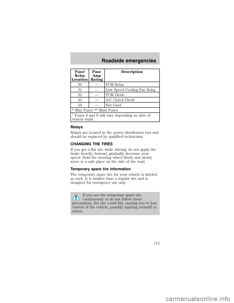
Fuse/
Relay
LocationFuse
Amp
RatingDescription
30 Ð PCM Relay
31 Ð Low Speed Cooling Fan Relay
32 Ð PCM Diode
33 Ð A/C Clutch Diode
34 Ð Not Used
* Mini Fuses ** Maxi Fuses
1Fuses 4 and 6 will vary depending on date of
vehicle build.
Relays
Relays are located in the power distribution box and
should be replaced by qualified technicians.
CHANGING THE TIRES
If you get a flat tire while driving, do not apply the
brake heavily. Instead, gradually decrease your
speed. Hold the steering wheel firmly and slowly
move to a safe place on the side of the road.
Temporary spare tire information
The temporary spare tire for your vehicle is labeled
as such. It is smaller than a regular tire and is
designed for emergency use only.
If you use the temporary spare tire
continuously or do not follow these
precautions, the tire could fail, causing you to lose
control of the vehicle, possibly injuring yourself or
others.
Roadside emergencies
115