Mercury Sable 2001 Owner's Manuals
Manufacturer: MERCURY, Model Year: 2001, Model line: Sable, Model: Mercury Sable 2001Pages: 240, PDF Size: 2.22 MB
Page 141 of 240

Fuse/Relay
LocationFuse Amp
RatingPassenger Compartment
Fuse Panel Description
37 15A Transmission Position Switch
38 5A GEM Park Neutral Switch
39 Ð Not Used
40 Ð Not Used
41 Ð Not Used
42 Ð Not Used
Power distribution box
The power distribution box is
located in the engine compartment.
The power distribution box contains
high-current fuses that protect your
vehicle's main electrical systems
from overloads.
Always disconnect the battery before servicing high current
fuses.
Always replace the cover to the Power Distribution Box before
reconnecting the battery or refilling fluid reservoirs.
If the battery has been disconnected and reconnected, refer to the
Batterysection of theMaintenance and carechapter.
Roadside emergencies
141
Page 142 of 240

The high-current fuses are coded as follows.
Fuse/Relay
LocationFuse Amp
RatingPower Distribution Box Description
1 60A** Fuse Junction Panel
2 30A** PCM Relay
3 60A** Fuse Junction Panel
4 Ð Not Used
5 Ð Not Used
6 Ð Not Used
7 40A** Starter Relay, Ignition Switch
8 20A** Transit Relay (Export only)
9 40A** Cooling Fan Relays
10 Ð Not Used
11 20A** Thermactor Relay (FFV only)
12 Ð Not Used
13 40A** Anti-Lock Brake Module Pump Feed
14 Ð Not Used
15 20A* Anti-Lock Brake Module Valve Solenoid
16 20A* Fuel Pump Relay
17 20A* Rear Control Unit, CD Changer, Cell Phone
18 20A* Power Point
19 15A* Right Headlamp
20 Ð Not Used
1
23
4
56
7
8
910
11 12
1314
1516 17
18
19202122
2324
25
29
3026 27 28
31
32
33
Roadside emergencies
142
Page 143 of 240

Fuse/Relay
LocationFuse Amp
RatingPower Distribution Box Description
21 15A* Left Headlamp
22 10A* A/C Clutch Relay, PCM Keep Alive Power
23 Ð Starter Motor Relay
24 Ð Low Speed Fan Relay
25 Ð Wiper Speed Relay
26 10A* Generator
27 5A* Rear Control Unit, Antenna
28 15A* HEGO Sensor Transmission Shift Solenoid,
Canister Vent, A/C Clutch Relay,
Thermactor Bypass Solenoid
29 Ð Wiper Park Relay
30 Ð Fuel Pump Relay
31 Ð PCM Power Relay
32 Ð High Speed Fan Relay
33 Ð A/C Clutch Relay
* Mini Fuses ** Maxi Fuses
Relays
Relays are located in the power distribution box and should be replaced
by qualified technicians.
CHANGING THE TIRES
If you get a flat tire while driving, do not apply the brake heavily.
Instead, gradually decrease your speed. Hold the steering wheel firmly
and slowly move to a safe place on the side of the road.
Temporary spare tire information
The temporary spare tire for your vehicle is labeled as such. It is smaller
than a regular tire and is designed for emergency use only.
If you use the temporary spare tire continuously or do not follow
these precautions, the tire could fail, causing you to lose control
of the vehicle, possibly injuring yourself or others.
Roadside emergencies
143
Page 144 of 240

When driving with the temporary spare tiredo not:
²exceed 80 km/h (50 mph) under any circumstances
²load the vehicle beyond maximum vehicle load rating listed on the
Safety Compliance Label
²tow a trailer
²use tire chains
²drive through an automatic car wash, because of the vehicle's reduced
ground clearance
²try to repair the temporary spare tire or remove it from its wheel
²use the wheel for any other type of vehicle
Tire change procedure
1. Park on a level surface, activate hazard flashers and set parking brake.
When one of the front wheels is off the ground, the transaxle
alone will not prevent the vehicle from moving or slipping off the
jack, even if the vehicle is in P (Park).
To prevent the vehicle from moving when you change a tire, be
sure the parking brake is set, then block (in both directions) the
wheel that is diagonally opposite (other side and end of the vehicle) to
the tire being changed.
If the vehicle slips off the jack, you or someone else could be
seriously injured.
2. Place gearshift lever in P (Park),
turn engine OFF, block the
diagonally opposite wheel, then
remove the spare tire, jack and lug
wrench.
Roadside emergencies
144
Page 145 of 240

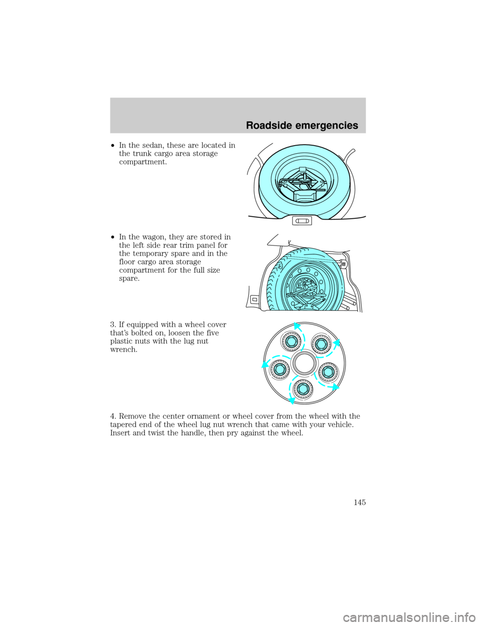
²In the sedan, these are located in
the trunk cargo area storage
compartment.
²In the wagon, they are stored in
the left side rear trim panel for
the temporary spare and in the
floor cargo area storage
compartment for the full size
spare.
3. If equipped with a wheel cover
that's bolted on, loosen the five
plastic nuts with the lug nut
wrench.
4. Remove the center ornament or wheel cover from the wheel with the
tapered end of the wheel lug nut wrench that came with your vehicle.
Insert and twist the handle, then pry against the wheel.
Roadside emergencies
145
Page 146 of 240

5. Loosen each wheel lug nut
one-half turn counterclockwise but
do not remove them until the wheel
is raised off the ground.
6. Put the jack in the jack notch
next to the door of the tire you are
changing. Turn the jack handle
clockwise until the wheel is
completely off the ground.
7. Remove the lug nuts with the lug
nut wrench.
8. Replace the flat tire with the spare tire, making sure the valve stem is
facing outward. Reinstall lug nuts until the wheel is snug against the hub.
Do not fully tighten the lug nuts until the wheel has been lowered.
9. Lower the wheel by turning the jack handle counterclockwise.
10. Remove the jack and fully
tighten the lug nuts in the order
shown.
1
4 3
2 5
Roadside emergencies
146
Page 147 of 240

11. Return the flat tire, jack and lug
wrench to their proper storage
locations. Make sure the jack is
fastened so it does not rattle when
you drive.
12. Unblock the wheels.
JUMP STARTING YOUR VEHICLE
The gases around the battery can explode if exposed to flames,
sparks, or lit cigarettes. An explosion could result in injury or
vehicle damage.
Do not push start your vehicle. You could damage the catalytic
converter.
Batteries contain sulfuric acid which can burn skin, eyes, and
clothing, if contacted.
Do not attempt to push start your vehicle. Automatic
transmissions do not have push-start capability.
Preparing your vehicle
When the battery is disconnected or a new battery is installed, the
transmission must relearn its adaptive strategy. As a result of this, the
transmission may shift firmly. This operation is considered normal and
will not effect function or durability of the transmission. Over time, the
adaptive learning process will fully update transmission operation to its
optimum shift feel.
1.Use only a 12±volt supply to start your vehicle.
Roadside emergencies
147
Page 148 of 240

2. Do not disconnect the battery of the disabled vehicle as this could
damage the vehicle's electrical system.
3.
Park the booster vehicle close to the hood of the disabled vehicle
making sure the two vehiclesdo nottouch. Set the parking brake on both
vehicles and stay clear of the engine cooling fan and other moving parts.
4. Check all battery terminals and remove any excessive corrosion before
you attach the battery cables. Ensure that vent caps are tight and level.
5. Turn the heater fan on in both vehicles to protect any electrical
surges. Turn all other accessories off.
Connecting the jumper cables
1. Connect the positive (+) booster cable to the positive (+) terminal of
the discharged battery.
Note:In the illustrations,lightning boltsare used to designate the
assisting (boosting) battery.
2. Connect the other end of the positive (+) cable to the positive (+)
terminal of the assisting battery.
+–+–
+–+–
Roadside emergencies
148
Page 149 of 240

3. Connect the negative (-) cable to the negative (-) terminal of the
assisting battery.
4. Make the final connection of the negative (-) cable. Make the
connection to an exposed metal part of the stalled vehicle's engine, away
from the battery and the carburetor/fuel injection system.Do notuse
fuel lines, engine rocker covers or the intake manifold asgrounding
points.
Do not connect the end of the second cable to the negative (-)
terminal of the battery to be jumped. A spark may cause an
explosion of the gases that surround the battery.
5. Ensure that the cables are clear of fan blades, belts, moving parts of
both engines, or any fuel delivery system parts.
+–+–
+–+–
Roadside emergencies
149
Page 150 of 240

Jump starting
1. Start the engine of the booster vehicle and run the engine at
moderately increased speed.
2. Start the engine of the disabled vehicle.
3. Once the disabled vehicle has been started, run both engines for an
additional three minutes before disconnecting the jumper cables.
Removing the jumper cables
Remove the jumper cables in the reverse order that they were
connected.
1. Remove the jumper cable from thegroundmetal surface.
2. Remove the jumper cable on the negative (-) connection of the
booster vehicle's battery.
+–+–
+–+–
Roadside emergencies
150