lock Mercury Sable 2001 s Service Manual
[x] Cancel search | Manufacturer: MERCURY, Model Year: 2001, Model line: Sable, Model: Mercury Sable 2001Pages: 240, PDF Size: 2.22 MB
Page 116 of 240

Using the engine block heater (if equipped)
An engine block heater warms the engine coolant, which improves
starting, warms up the engine faster and allows the heater-defroster
system to respond quickly. Use of an engine block heater is strongly
recommended if you live in a region where temperatures reach -23ÉC
(-10ÉF) or below.
For best results, plug the heater in at least three hours before starting
the vehicle. Using the heater for longer than three hours will not harm
the engine, so the heater can be plugged in the night before starting the
vehicle.
To prevent electrical shock, do not use your heater with
ungrounded electrical systems or two-pronged (cheater)
adapters.
Guarding against exhaust fumes
Although odorless and colorless, carbon monoxide is present in exhaust
fumes. Take precautions to avoid its dangerous effects.
If you ever smell exhaust fumes of any kind inside your vehicle,
have your dealer inspect and fix your vehicle immediately. Do
not drive if you smell exhaust fumes. These fumes are harmful and
could kill you.
Have the exhaust and body ventilation systems checked whenever:
²the vehicle is raised for service.
²the sound of the exhaust system changes.
²the vehicle has been damaged in a collision.
WARNING:Engine exhaust, some of its constituents, and
certain vehicle components contain or emit chemicals known to
the State of California to cause cancer and birth defects or other
reproductive harm. In addition, certain fluids contained in vehicles and
certain products of component wear contain or emit chemicals known
to the State of California to cause cancer and birth defects or other
reproductive harm.
Starting
116
Page 118 of 240
BRAKES
Your service brakes are self-adjusting. Refer to the scheduled
maintenance guide for scheduled maintenance.
Occasional brake noise is normal and often does not indicate a
performance concern with the vehicle's brake system. In normal
operation, automotive brake systems may emit occasional or intermittent
squeal or groan noises when the brakes are applied. Such noises are
usually heard during the first few brake applications in the morning;
however, they may be heard at any time while braking and can be
aggravated by environmental conditions such as cold, heat, moisture,
road dust, salt or mud. If a ªmetal-to-metal,º ªcontinuous grindingº or
ªcontinuous squealº sound is present while braking, the brake linings
may be worn-out and should be inspected by a qualified service
technician.
Anti-lock brake system (ABS) (if equipped)
On vehicles equipped with an anti-lock braking system (ABS), a noise
from the hydraulic pump motor and pulsation in the pedal may be
observed during ABS braking events. Pedal pulsation coupled with noise
while braking under panic conditions or on loose gravel, bumps, wet or
snowy roads is normal and indicates proper functioning of the vehicle's
anti-lock brake system. The ABS performs a self-check after you start
the engine and begin to drive away. A brief mechanical noise may be
heard during this test. This is normal. If a malfunction is found, the ABS
warning light will come on. If the vehicle has continuous vibration or
shudder in the steering wheel while braking, the vehicle should be
inspected by a qualified service technician.
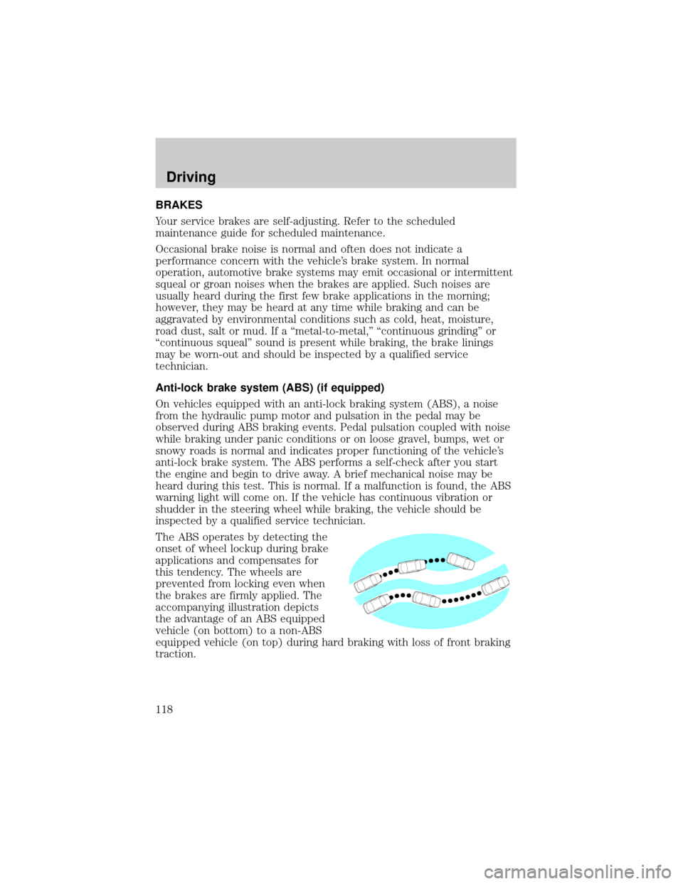
The ABS operates by detecting the
onset of wheel lockup during brake
applications and compensates for
this tendency. The wheels are
prevented from locking even when
the brakes are firmly applied. The
accompanying illustration depicts
the advantage of an ABS equipped
vehicle (on bottom) to a non-ABS
equipped vehicle (on top) during hard braking with loss of front braking
traction.
Driving
118
Page 119 of 240
ABS warning lampABS
TheABSwarning lamp in the instrument cluster momentarily illuminates
when the ignition is turned to the ON position. If the light does not
illuminate momentarily at start up, remains on or continues to flash, the
ABS needs to be serviced.
With the ABS light on, the anti-lock
brake system is disabled and normal
braking is still effective unless the
brake warning light also remains
illuminated with parking brake
released. (If your brake warning lamp illuminates, have your vehicle
serviced immediately.)
Using ABS
²In an emergency or when maximum efficiency from the four wheel
ABS is required, apply continuous force on the brake. The four wheel
ABS will be activated immediately, thus allowing you to retain full
steering control of your vehicle and, providing there is sufficient
space, will enable you to avoid obstacles and bring the vehicle to a
controlled stop.
²The Anti-Lock system does not decrease the time necessary to apply
the brakes or always reduce stopping distance. Always leave enough
room between your vehicle and the vehicle in front of you to stop.
²We recommend that you familiarize yourself with this braking
technique. However, avoid taking any unnecessary risks.
P!
BRAKE
Driving
119
Page 121 of 240
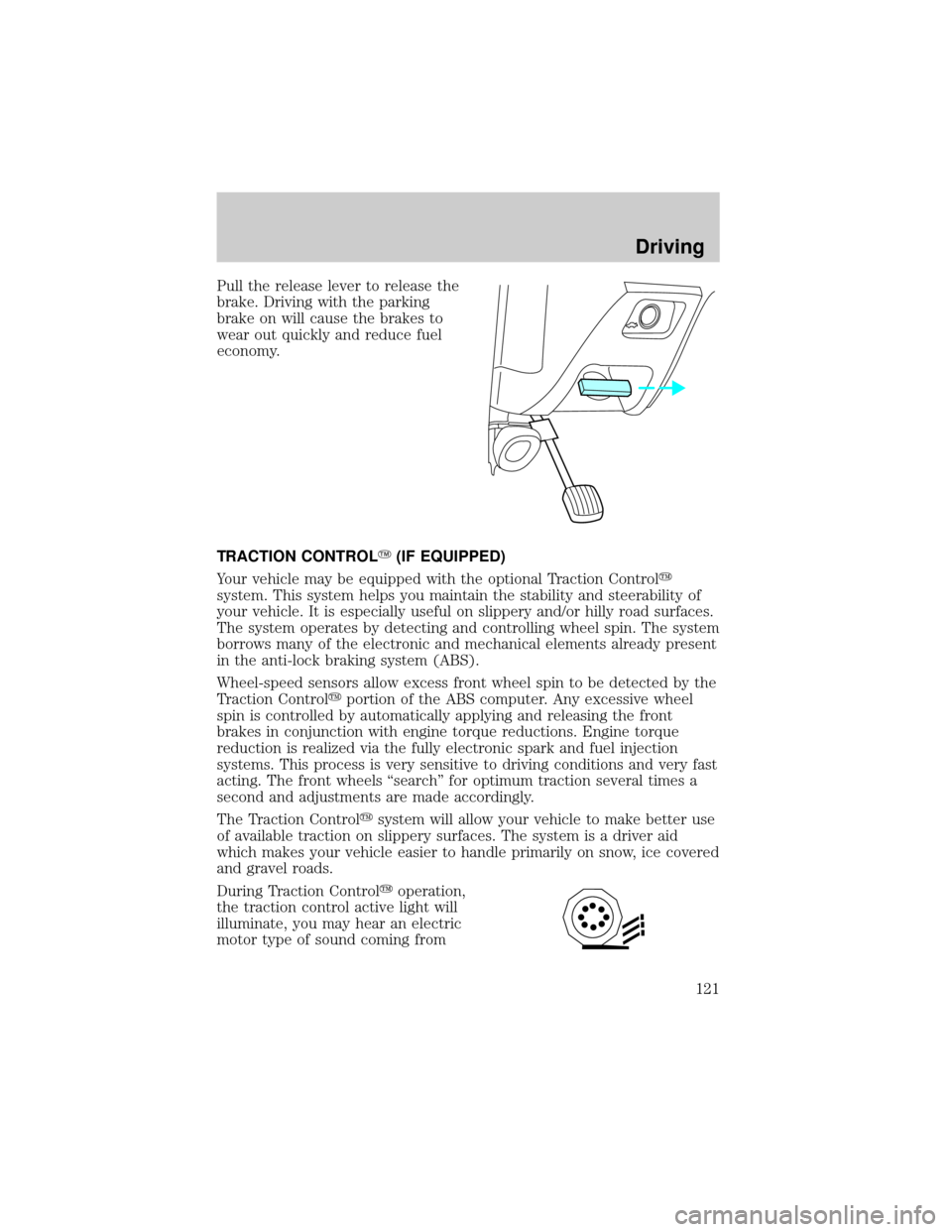
Pull the release lever to release the
brake. Driving with the parking
brake on will cause the brakes to
wear out quickly and reduce fuel
economy.
TRACTION CONTROLY(IF EQUIPPED)
Your vehicle may be equipped with the optional Traction Controly
system. This system helps you maintain the stability and steerability of
your vehicle. It is especially useful on slippery and/or hilly road surfaces.
The system operates by detecting and controlling wheel spin. The system
borrows many of the electronic and mechanical elements already present
in the anti-lock braking system (ABS).
Wheel-speed sensors allow excess front wheel spin to be detected by the
Traction Controlyportion of the ABS computer. Any excessive wheel
spin is controlled by automatically applying and releasing the front
brakes in conjunction with engine torque reductions. Engine torque
reduction is realized via the fully electronic spark and fuel injection
systems. This process is very sensitive to driving conditions and very fast
acting. The front wheels ªsearchº for optimum traction several times a
second and adjustments are made accordingly.
The Traction Controlysystem will allow your vehicle to make better use
of available traction on slippery surfaces. The system is a driver aid
which makes your vehicle easier to handle primarily on snow, ice covered
and gravel roads.
During Traction Controlyoperation,
the traction control active light will
illuminate, you may hear an electric
motor type of sound coming from
Driving
121
Page 123 of 240
AUTOMATIC TRANSAXLE OPERATION
Brake-shift interlock
This vehicle is equipped with a brake-shift interlock feature that prevents
the gearshift lever from being moved from P (Park) when the ignition is
in the ON position unless brake pedal is depressed.
If you cannot move the gearshift lever out of P (Park) with ignition in
the ON position and the brake pedal depressed:
1. Apply the parking brake, turn ignition key to LOCK, then remove the
key.
2. Insert the key and turn it to OFF. Apply the brake pedal and shift to N
(Neutral).
3. Start the vehicle.
If it is necessary to use the above procedure to move the gearshift lever,
it is possible that a fuse has blown or the vehicle's brakelamps are not
operating properly. Refer toFuses and relaysin theRoadside
emergencieschapter.
Do not drive your vehicle until you verify that the brakelamps
are working.
If your vehicle gets stuck in mud or snow, it may be rocked out by
shifting from forward and reverse gears while stopping between shifts, in
a steady pattern. Press lightly on the accelerator in each gear. If
necessary, try turning the Traction Controlysystem off. This will allow
the wheels to spin, which may help to free your stuck vehicle. For more
information, refer toTraction Controly(if equipped)in this chapter.
Do not rock the vehicle if the engine is not at normal operating
temperature or damage to the transaxle may occur.
Do not rock the vehicle for more than a few minutes or damage
to the transaxle and tires may occur or the engine may overheat.
Always set the parking brake fully and make sure the gearshift is
latched in P (Park). Turn off the ignition whenever you leave
your vehicle.
Driving
123
Page 125 of 240

Understanding gearshift positions
P (Park)
Always come to a complete stop
before shifting into P (Park). Make
sure the gearshift lever is securely
latched in P (Park). This locks the
transaxle and prevent the front
wheels from rotating.
Always set the parking
brake fully and make sure
the gearshift is latched in P
(Park). Turn off the ignition
whenever you leave your vehicle.
R (Reverse)
With the gearshift lever in R
(Reverse), the vehicle will move
backward. You should always come
to a complete stop before shifting
into and out of R (Reverse).
PRNDD1
PRNDD1
Driving
125
Page 126 of 240

N (Neutral)
With the gearshift lever in the N
(Neutral) position, the vehicle can
be started and is free to roll. Hold
the brake pedal down while in this
position.
(Overdrive)
The(Overdrive) position is the
normal driving position for an
automatic overdrive transaxle.
When in the
(Overdrive)
position, the transaxle works the
same way as when in D (Drive).
However, when your vehicle cruises
at a constant speed for any length
of time, the transaxle shifts into a
fourth gear (Overdrive) and allows
the torque converter to lock-up.
Overdrive will increase your fuel
economy when you travel at cruising
speeds.
Overdrive may not be appropriate
for certain terrains. If the transaxle shifts back and forth between third
and fourth gears while you are driving on hilly roads, or if your vehicle
requires additional power for climbing hills, shift into D (Drive).
PRNDD1
PRNDD1
Driving
126
Page 135 of 240

GETTING ROADSIDE ASSISTANCE
To fully assist you should you have a vehicle concern, Ford offers a
complimentary roadside assistance program. This program is separate
from the New Vehicle Limited Warranty. The service is available:
²24±hours, seven days a week
²for the Basic warranty period (Canada) or New Vehicle Limited
Warranty period (U.S.) of three years or 60 000 km (36 000 miles),
whichever comes first on Ford and Mercury vehicles, and four years or
80 000 km (50 000 miles) on Lincoln vehicles
Roadside assistance will cover:
²changing a flat tire
²jump-starts
²lock-out assistance
²fuel delivery
²towing of your disabled vehicle up to 56.3 kms (35 miles) from the
point of pickup (this can include to the nearest Ford dealership, or
your selling dealer if within the specified distance.) One tow per
disablement. Even non-warranty related tows, like accidents or getting
stuck in the mud or snow, are covered (some exclusions apply, such
as impound towing or repossession).
Using roadside assistance
Complete the roadside assistance identification card and place it in your
wallet for quick reference. In the United States, this card is found in the
Owner Guide portfolio in the glove compartment in Ford vehicles and is
mailed to you if you own a Mercury or Lincoln. In Canada, the card is
found in the Roadside Assistance book in the glove compartment.
To receive roadside assistance in the United States for Ford or Mercury
vehicles, call 1±800±241±3673 or if you own a Lincoln vehicle, call
1±800±521±4140. In Canada call 1±800±665±2006.
Should you need to arrange roadside assistance for yourself, Ford will
reimburse a reasonable amount. To obtain information about
reimbursement, call 1±800±241±3673 in the United States for Ford or
Mercury vehicles; or if you own a Lincoln vehicle, call 1±800±521±4140.
Call 1±800±665±2006 in Canada.
Roadside emergencies
135
Page 140 of 240
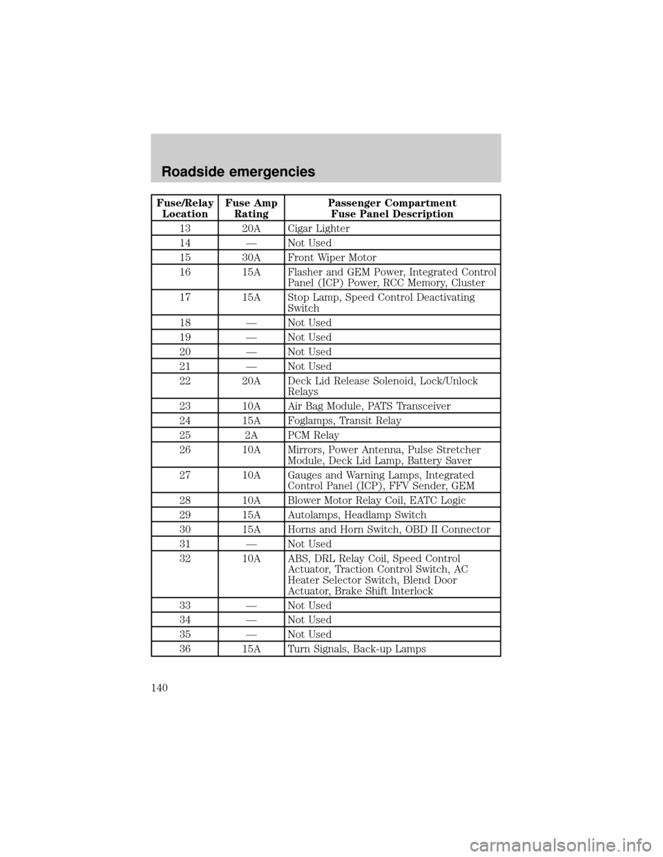
Fuse/Relay
LocationFuse Amp
RatingPassenger Compartment
Fuse Panel Description
13 20A Cigar Lighter
14 Ð Not Used
15 30A Front Wiper Motor
16 15A Flasher and GEM Power, Integrated Control
Panel (ICP) Power, RCC Memory, Cluster
17 15A Stop Lamp, Speed Control Deactivating
Switch
18 Ð Not Used
19 Ð Not Used
20 Ð Not Used
21 Ð Not Used
22 20A Deck Lid Release Solenoid, Lock/Unlock
Relays
23 10A Air Bag Module, PATS Transceiver
24 15A Foglamps, Transit Relay
25 2A PCM Relay
26 10A Mirrors, Power Antenna, Pulse Stretcher
Module, Deck Lid Lamp, Battery Saver
27 10A Gauges and Warning Lamps, Integrated
Control Panel (ICP), FFV Sender, GEM
28 10A Blower Motor Relay Coil, EATC Logic
29 15A Autolamps, Headlamp Switch
30 15A Horns and Horn Switch, OBD II Connector
31 Ð Not Used
32 10A ABS, DRL Relay Coil, Speed Control
Actuator, Traction Control Switch, AC
Heater Selector Switch, Blend Door
Actuator, Brake Shift Interlock
33 Ð Not Used
34 Ð Not Used
35 Ð Not Used
36 15A Turn Signals, Back-up Lamps
Roadside emergencies
140
Page 142 of 240

The high-current fuses are coded as follows.
Fuse/Relay
LocationFuse Amp
RatingPower Distribution Box Description
1 60A** Fuse Junction Panel
2 30A** PCM Relay
3 60A** Fuse Junction Panel
4 Ð Not Used
5 Ð Not Used
6 Ð Not Used
7 40A** Starter Relay, Ignition Switch
8 20A** Transit Relay (Export only)
9 40A** Cooling Fan Relays
10 Ð Not Used
11 20A** Thermactor Relay (FFV only)
12 Ð Not Used
13 40A** Anti-Lock Brake Module Pump Feed
14 Ð Not Used
15 20A* Anti-Lock Brake Module Valve Solenoid
16 20A* Fuel Pump Relay
17 20A* Rear Control Unit, CD Changer, Cell Phone
18 20A* Power Point
19 15A* Right Headlamp
20 Ð Not Used
1
23
4
56
7
8
910
11 12
1314
1516 17
18
19202122
2324
25
29
3026 27 28
31
32
33
Roadside emergencies
142