tow Mercury Sable 2001 Owner's Manuals
[x] Cancel search | Manufacturer: MERCURY, Model Year: 2001, Model line: Sable, Model: Mercury Sable 2001Pages: 240, PDF Size: 2.22 MB
Page 2 of 240
The following warning may be required by California law:
CALIFORNIA Proposition 65 Warning
WARNING:Engine exhaust, some of its constituents, and
certain vehicle components contain or emit chemicals known to
the State of California to cause cancer and birth defects or other
reproductive harm. In addition, certain fluids contained in vehicles and
certain products of component wear contain or emit chemicals known
to the State of California to cause cancer and birth defects or other
reproductive harm.
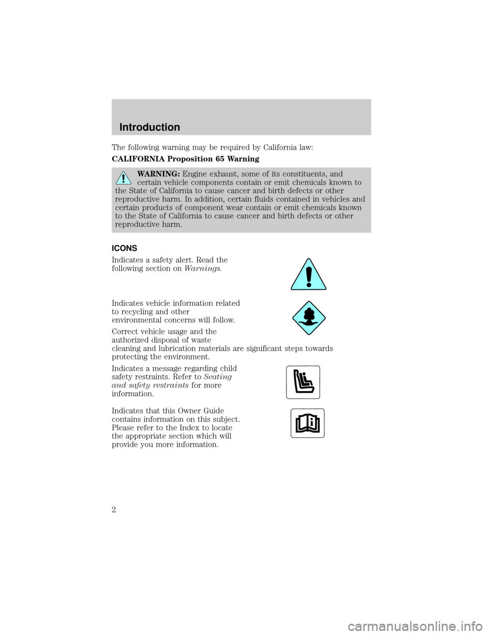
ICONS
Indicates a safety alert. Read the
following section onWarnings.
Indicates vehicle information related
to recycling and other
environmental concerns will follow.
Correct vehicle usage and the
authorized disposal of waste
cleaning and lubrication materials are significant steps towards
protecting the environment.
Indicates a message regarding child
safety restraints. Refer toSeating
and safety restraintsfor more
information.
Indicates that this Owner Guide
contains information on this subject.
Please refer to the Index to locate
the appropriate section which will
provide you more information.
Introduction
2
Page 10 of 240
Theindicator light illuminates when the ignition is first turned to
the ON position to check the bulb. If it comes on after the engine is
started, one of the engine's emission control systems may be
malfunctioning. The light may illuminate without a driveability concern
being noted. The vehicle will usually be drivable and will not require
towing.
What you should do if thelight illuminates
Light turns on solid:
This means that the OBD II system has detected a malfunction.
Temporary malfunctions may cause your
light to illuminate.
Examples are:
1. The vehicle has run out of fuel. (The engine may misfire or run
poorly.)
2. Poor fuel quality or water in the fuel.
3. The fuel cap may not have been properly installed and securely
tightened.
These temporary malfunctions can be corrected by filling the fuel tank
with high quality fuel of the recommended octane and/or properly
installing and securely tightening the gas cap. After three driving cycles
without these or any other temporary malfunctions present, the
light should turn off. (A driving cycle consists of a cold engine startup
followed by mixed city/highway driving.) No additional vehicle service is
required.
If the
light remains on, have your vehicle serviced at the first
available opportunity.
Light is blinking:
Engine misfire is occurring which could damage your catalytic converter.
You should drive in a moderate fashion (avoid heavy acceleration and
deceleration) and have your vehicle serviced at the first available
opportunity.
Under engine misfire conditions, excessive exhaust temperatures
could damage the catalytic converter, the fuel system, interior
floor coverings or other vehicle components, possibly causing a fire.
Instrumentation
10
Page 17 of 240
HEADLAMP CONTROL
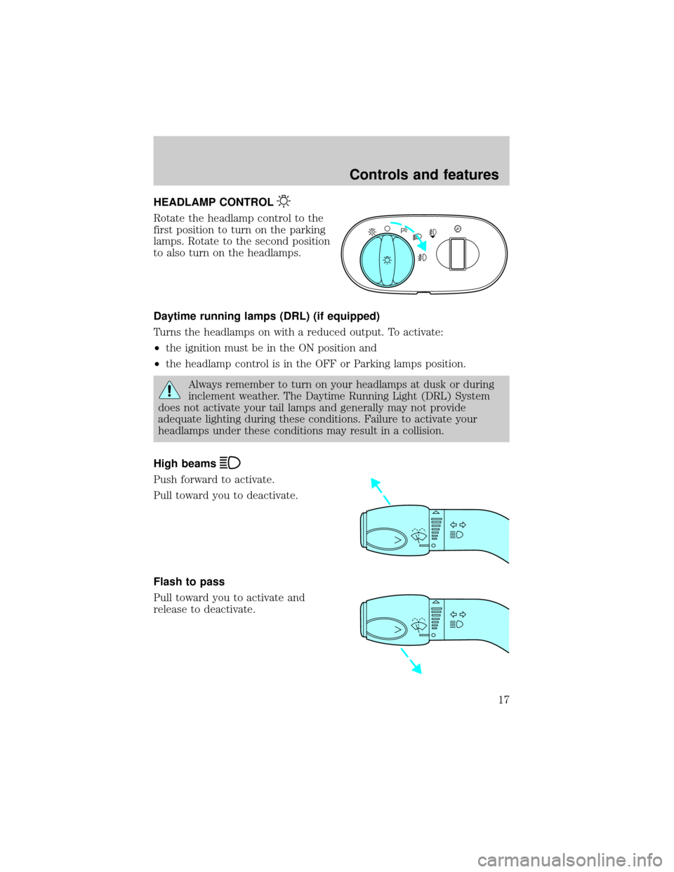
Rotate the headlamp control to the
first position to turn on the parking
lamps. Rotate to the second position
to also turn on the headlamps.
Daytime running lamps (DRL) (if equipped)
Turns the headlamps on with a reduced output. To activate:
²the ignition must be in the ON position and
²the headlamp control is in the OFF or Parking lamps position.
Always remember to turn on your headlamps at dusk or during
inclement weather. The Daytime Running Light (DRL) System
does not activate your tail lamps and generally may not provide
adequate lighting during these conditions. Failure to activate your
headlamps under these conditions may result in a collision.
High beams
Push forward to activate.
Pull toward you to deactivate.
Flash to pass
Pull toward you to activate and
release to deactivate.
A
Controls and features
17
Page 18 of 240
Foglamp control (if equipped)
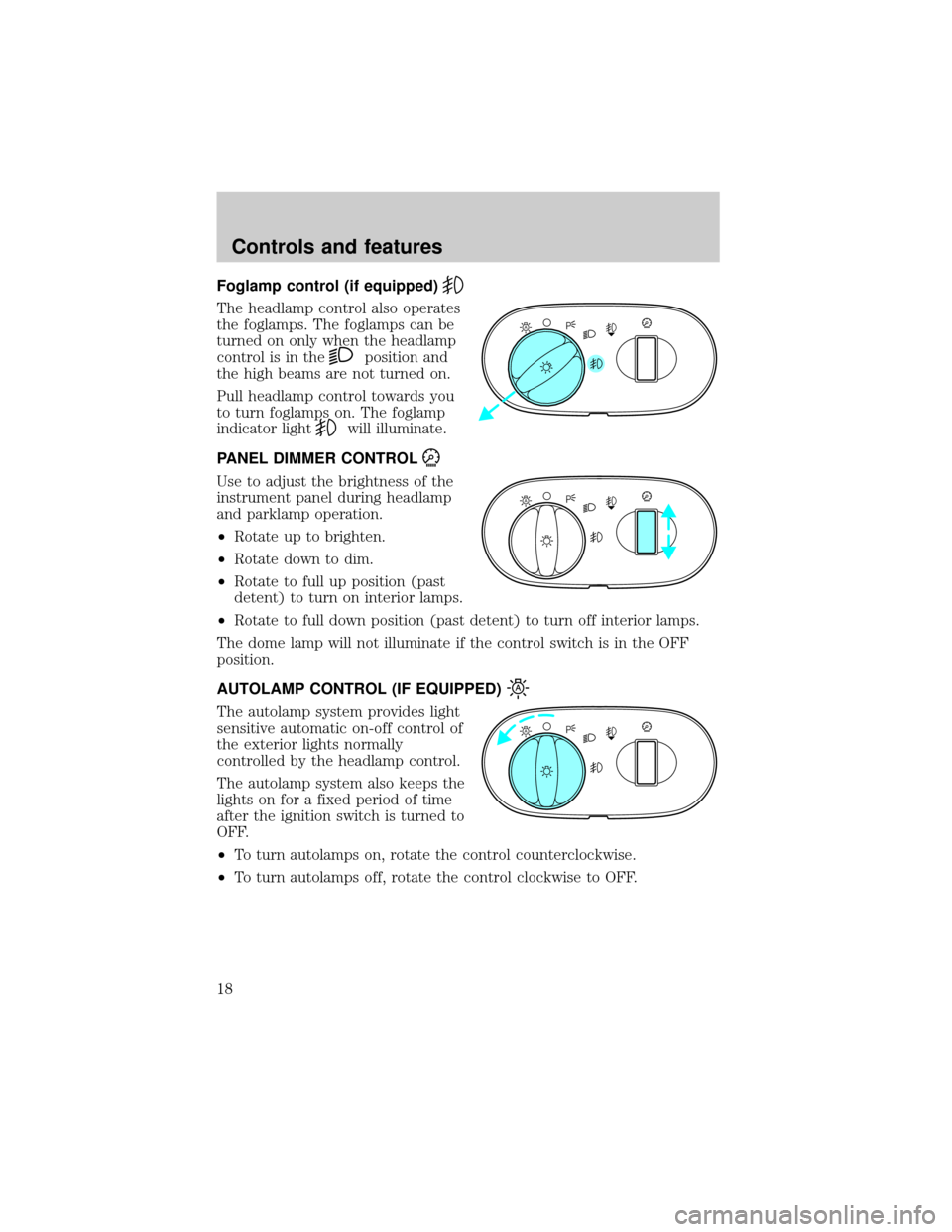
The headlamp control also operates
the foglamps. The foglamps can be
turned on only when the headlamp
control is in the
position and
the high beams are not turned on.
Pull headlamp control towards you
to turn foglamps on. The foglamp
indicator light
will illuminate.
PANEL DIMMER CONTROL
Use to adjust the brightness of the
instrument panel during headlamp
and parklamp operation.
²Rotate up to brighten.
²Rotate down to dim.
²Rotate to full up position (past
detent) to turn on interior lamps.
²Rotate to full down position (past detent) to turn off interior lamps.
The dome lamp will not illuminate if the control switch is in the OFF
position.
AUTOLAMP CONTROL (IF EQUIPPED)
The autolamp system provides light
sensitive automatic on-off control of
the exterior lights normally
controlled by the headlamp control.
The autolamp system also keeps the
lights on for a fixed period of time
after the ignition switch is turned to
OFF.
²To turn autolamps on, rotate the control counterclockwise.
²To turn autolamps off, rotate the control clockwise to OFF.
A
A
A
Controls and features
18
Page 46 of 240
²Station overload.Weak signals are sometimes captured by stronger
signals when you pass a broadcast tower. A stronger signal may
temporarily overtake a weaker signal and play while the weak station
frequency is displayed.
The audio system automatically switches to single channel reception if it
will improve the reception of a station normally received in stereo.
Audio system warranties and service
Refer to the ªWarranty Guideº for audio system warranty information.
If service is necessary, see your dealer or a qualified technician.
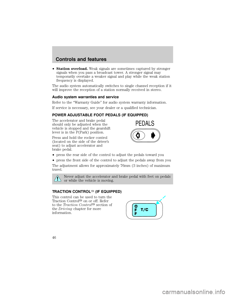
POWER ADJUSTABLE FOOT PEDALS (IF EQUIPPED)
The accelerator and brake pedal
should only be adjusted when the
vehicle is stopped and the gearshift
lever is in the P(Park) position.
Press and hold the rocker control
(located on the side of the driver's
seat) to adjust accelerator and
brake pedal.
²press the rear side of the control to adjust the pedals toward you
²press the front side of the control to adjust the pedals away from you
The adjustment allows for approximately 76mm (3 inches) of maximum
travel.
Never adjust the accelerator and brake pedal with feet on pedals
or while the vehicle is moving.
TRACTION CONTROLY(IF EQUIPPED)
This control can be used to turn the
Traction Controlyon or off. Refer
to theTraction Controlysection of
theDrivingchapter for more
information.
PEDALS
T/C O
F
F
Controls and features
46
Page 52 of 240
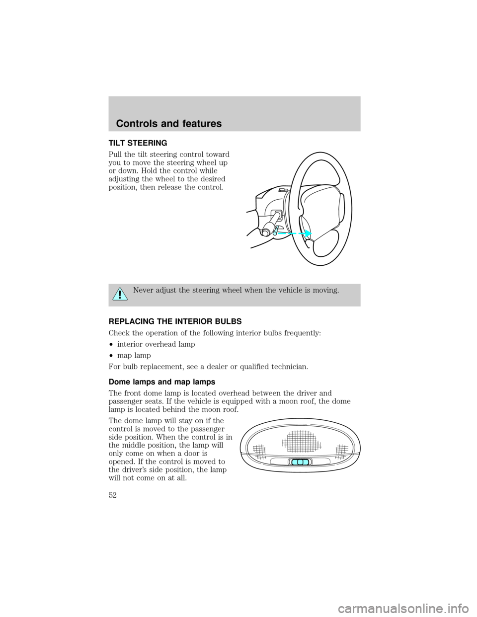
TILT STEERING
Pull the tilt steering control toward
you to move the steering wheel up
or down. Hold the control while
adjusting the wheel to the desired
position, then release the control.
Never adjust the steering wheel when the vehicle is moving.
REPLACING THE INTERIOR BULBS
Check the operation of the following interior bulbs frequently:
²interior overhead lamp
²map lamp
For bulb replacement, see a dealer or qualified technician.
Dome lamps and map lamps
The front dome lamp is located overhead between the driver and
passenger seats. If the vehicle is equipped with a moon roof, the dome
lamp is located behind the moon roof.
The dome lamp will stay on if the
control is moved to the passenger
side position. When the control is in
the middle position, the lamp will
only come on when a door is
opened. If the control is moved to
the driver's side position, the lamp
will not come on at all.
Controls and features
52
Page 59 of 240

CENTER CONSOLE
Your vehicle may be equipped with a variety of console features. These
include:
²Utility compartment
²Bin mat (snap-in)
²Cupholders (front and rear)
²Coin holder slots
²Compact disc changer (if equipped)
²Tissue holder
²Rear A/C vent
²Rear ashtray (see your Ford, Lincoln Mercury dealer to obtain rear
ashtray
Use only soft cups in the cupholder. Hard objects can injure you
in a collision.
If your vehicle is equipped with the column shift and a bench seat, it has
a center console in the center front seating position.
The center console has similar features as the full console. To open the
storage compartment, raise the armrest and pull the strap on the seat up
and toward the front of the vehicle. The rear seat area is provided with
dual cupholders.
POSITIVE RETENTION FLOOR MAT
Position the floor mat so that the
eyelet is over the pointed end of the
retention post and rotate forward to
lock in. Make sure that the mat does
not interfere with the operation of
the accelerator or the brake pedal.
To remove the floor mat, reverse the
installation procedure.
Controls and features
59
Page 61 of 240

CARGO AREA FEATURES
Storage compartment
Your vehicle comes equipped with a
storage compartment in the floor of
the cargo area. An additional
compartment is in the rear trim
panel on the right. Always put the
load you are carrying as far forward
as possible.
Cargo net (if equipped) (Wagon)
The cargo net secures lightweight
objects in the cargo area. Attach the
net to the anchors provided. Do not
put more than 22 kg (50 lbs.) in the
net. This net is not designed to
restrain objects during a collision.
Cargo cover (if equipped)
Your vehicle may be equipped with a cargo area shade that covers the
luggage compartment of your vehicle.
To install the shade:
1. Fasten the cover into the
mounting brackets (make sure the
cover is right side up).
2. Pull the end of the shade toward
you and hook the sides into the
notches (right side first) in the rear
trim panels.
Controls and features
61
Page 62 of 240

To prevent the possibility of injuries, the fasteners for the cargo
area cover must be properly attached to the mounting clips on
the rear trim panels.
Do not place any objects on the cargo area cover. They may
obstruct your vision or strike occupants of the vehicle in the
case of a sudden stop or collision.
The cover may cause injury in a sudden stop or accident if it is
not securely installed.
Rewinding the shade
With extended use, the cargo shade may lose its spring tension. If this
occurs, the shade must be manually rewound. This is a two-person
operation.
1. Remove the shade from the vehicle and extend it with the smooth
grain facing you.
2. Wrap the vinyl around the roller
tube twice. Tuck the edges of the
vinyl inside the end cap with each
wrap.
3. Fold the edges of the vinyl
towards the center, making sure
that the edges clear the end cap
slots. Use tape or a rubber band to
hold the vinyl to the left side of the
tube.
Controls and features
62
Page 63 of 240
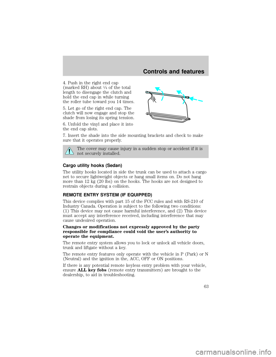
4. Push in the right end cap
(marked RH) about1¤4of the total
length to disengage the clutch and
hold the end cap in while turning
the roller tube toward you 14 times.
5. Let go of the right end cap. The
clutch will now engage and stop the
shade from losing its spring tension.
6. Unfold the vinyl and place it into
the end cap slots.
7. Insert the shade into the side mounting brackets and check to make
sure that it operates properly.
The cover may cause injury in a sudden stop or accident if it is
not securely installed.
Cargo utility hooks (Sedan)
The utility hooks located in side the trunk can be used to attach a cargo
net to secure lightweight objects or hang small items on. Do not hang
more than 12 kg (20 lbs) on the hooks. The hooks are not designed to
restrain objects during a collision.
REMOTE ENTRY SYSTEM (IF EQUIPPED)
This device complies with part 15 of the FCC rules and with RS-210 of
Industry Canada. Operation is subject to the following two conditions:
(1) This device may not cause harmful interference, and (2) This device
must accept any interference received, including interference that may
cause undesired operation.
Changes or modifications not expressly approved by the party
responsible for compliance could void the user's authority to
operate the equipment.
The remote entry system allows you to lock or unlock all vehicle doors,
trunk and liftgate without a key.
The remote entry features only operate with the vehicle in P (Park) or N
(Neutral) and the ignition in the, ACC, OFF or ON positions.
If there is any potential remote keyless entry problem with your vehicle,
ensureALL key fobs(remote entry transmitters) are brought to the
dealership, to aid in troubleshooting.
Controls and features
63