Mercury Sable 2002 Owner's Manuals
Manufacturer: MERCURY, Model Year: 2002, Model line: Sable, Model: Mercury Sable 2002Pages: 240, PDF Size: 3.53 MB
Page 151 of 240
your vehicle including both gross vehicle weight and front and rear gross
axle weight rating limits. Under no circumstance should these limitations
be exceeded.
Exceeding any vehicle weight rating limitation could result in
serious damage to the vehicle loss of vehicle control, vehicle
rollover, and/or personal injury.
TRAILER TOWING
Your vehicle is classified as a light duty towing vehicle. The amount of
weight you can safely tow depends on the type of engine you have in
your vehicle. Your vehicle does not come from the factory fully equipped
to tow. No towing packages are available through Ford or
Mercury/Lincoln dealers. Do not tow a trailer until your vehicle has been
driven at least 800 km (500 miles). If towing with a station wagon, inflate
the rear tires to 35 psi.
Towing a trailer places an additional load on your vehicle’s engine,
transaxle, brakes, tires and suspension. Inspect these components
carefully after towing.
In order to identify your vehicle’s engine, refer toIdentifying
components in the engine compartmentin theMaintenance and
specificationschapter.
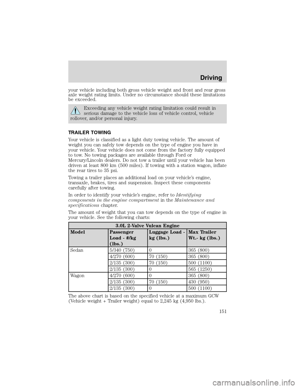
The amount of weight that you can tow depends on the type of engine in
your vehicle. See the following charts:
3.0L 2-Valve Vulcan Engine
Model Passenger
Load - #/kg
(lbs.)Luggage Load -
kg (lbs.)Max Trailer
Wt.- kg (lbs.)
Sedan 5/340 (750) 0 365 (800)
4/270 (600) 70 (150) 365 (800)
2/135 (300) 70 (150) 500 (1100)
2/135 (300) 0 565 (1250)
Wagon 4/270 (600) 0 365 (800)
2/135 (300) 70 (150) 430 (950)
2/135 (300) 0 500 (1100)
The above chart is based on the specified vehicle at a maximum GCW
(Vehicle weight + Trailer weight) equal to 2,245 kg (4,950 lbs.).
Driving
151
Page 152 of 240
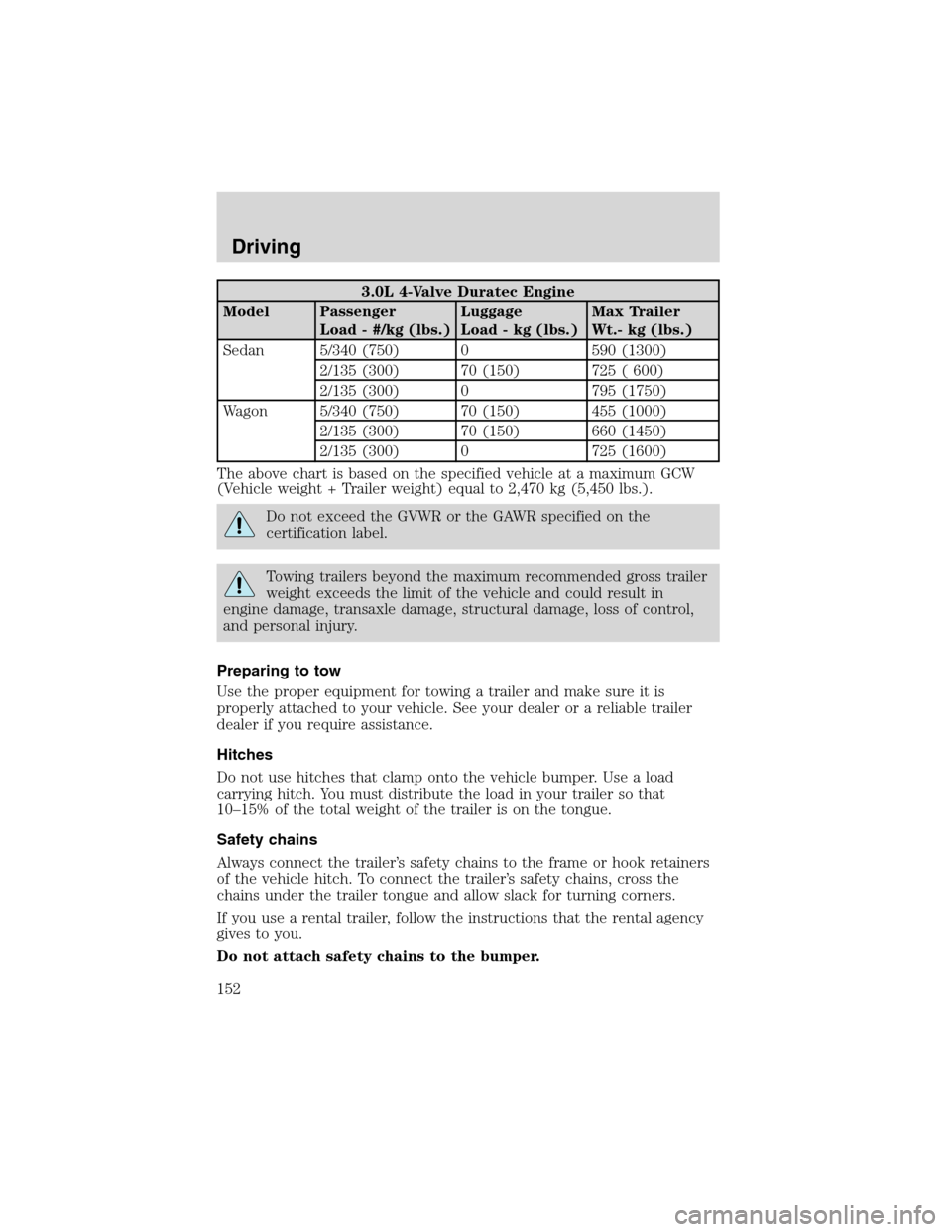
3.0L 4-Valve Duratec Engine
Model Passenger
Load - #/kg (lbs.)Luggage
Load - kg (lbs.)Max Trailer
Wt.- kg (lbs.)
Sedan 5/340 (750) 0 590 (1300)
2/135 (300) 70 (150) 725 ( 600)
2/135 (300) 0 795 (1750)
Wagon 5/340 (750) 70 (150) 455 (1000)
2/135 (300) 70 (150) 660 (1450)
2/135 (300) 0 725 (1600)
The above chart is based on the specified vehicle at a maximum GCW
(Vehicle weight + Trailer weight) equal to 2,470 kg (5,450 lbs.).
Do not exceed the GVWR or the GAWR specified on the
certification label.
Towing trailers beyond the maximum recommended gross trailer
weight exceeds the limit of the vehicle and could result in
engine damage, transaxle damage, structural damage, loss of control,
and personal injury.
Preparing to tow
Use the proper equipment for towing a trailer and make sure it is
properly attached to your vehicle. See your dealer or a reliable trailer
dealer if you require assistance.
Hitches
Do not use hitches that clamp onto the vehicle bumper. Use a load
carrying hitch. You must distribute the load in your trailer so that
10–15% of the total weight of the trailer is on the tongue.
Safety chains
Always connect the trailer’s safety chains to the frame or hook retainers
of the vehicle hitch. To connect the trailer’s safety chains, cross the
chains under the trailer tongue and allow slack for turning corners.
If you use a rental trailer, follow the instructions that the rental agency
gives to you.
Do not attach safety chains to the bumper.
Driving
152
Page 153 of 240
Trailer brakes
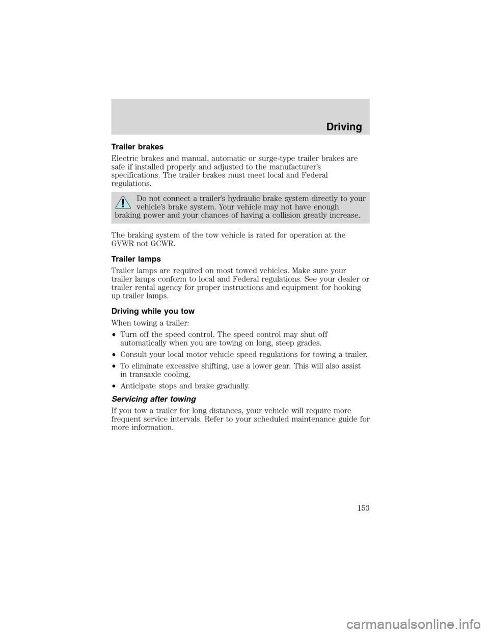
Electric brakes and manual, automatic or surge-type trailer brakes are
safe if installed properly and adjusted to the manufacturer’s
specifications. The trailer brakes must meet local and Federal
regulations.
Do not connect a trailer’s hydraulic brake system directly to your
vehicle’s brake system. Your vehicle may not have enough
braking power and your chances of having a collision greatly increase.
The braking system of the tow vehicle is rated for operation at the
GVWR not GCWR.
Trailer lamps
Trailer lamps are required on most towed vehicles. Make sure your
trailer lamps conform to local and Federal regulations. See your dealer or
trailer rental agency for proper instructions and equipment for hooking
up trailer lamps.
Driving while you tow
When towing a trailer:
•Turn off the speed control. The speed control may shut off
automatically when you are towing on long, steep grades.
•Consult your local motor vehicle speed regulations for towing a trailer.
•To eliminate excessive shifting, use a lower gear. This will also assist
in transaxle cooling.
•Anticipate stops and brake gradually.
Servicing after towing
If you tow a trailer for long distances, your vehicle will require more
frequent service intervals. Refer to your scheduled maintenance guide for
more information.
Driving
153
Page 154 of 240
Trailer towing tips
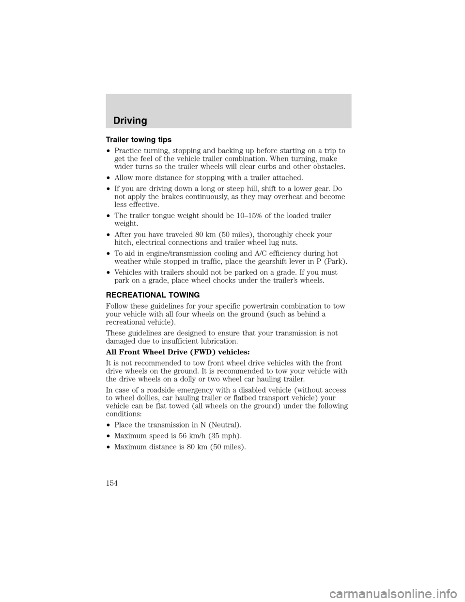
•Practice turning, stopping and backing up before starting on a trip to
get the feel of the vehicle trailer combination. When turning, make
wider turns so the trailer wheels will clear curbs and other obstacles.
•Allow more distance for stopping with a trailer attached.
•If you are driving down a long or steep hill, shift to a lower gear. Do
not apply the brakes continuously, as they may overheat and become
less effective.
•The trailer tongue weight should be 10–15% of the loaded trailer
weight.
•After you have traveled 80 km (50 miles), thoroughly check your
hitch, electrical connections and trailer wheel lug nuts.
•To aid in engine/transmission cooling and A/C efficiency during hot
weather while stopped in traffic, place the gearshift lever in P (Park).
•Vehicles with trailers should not be parked on a grade. If you must
park on a grade, place wheel chocks under the trailer’s wheels.
RECREATIONAL TOWING
Follow these guidelines for your specific powertrain combination to tow
your vehicle with all four wheels on the ground (such as behind a
recreational vehicle).
These guidelines are designed to ensure that your transmission is not
damaged due to insufficient lubrication.
All Front Wheel Drive (FWD) vehicles:
It is not recommended to tow front wheel drive vehicles with the front
drive wheels on the ground. It is recommended to tow your vehicle with
the drive wheels on a dolly or two wheel car hauling trailer.
In case of a roadside emergency with a disabled vehicle (without access
to wheel dollies, car hauling trailer or flatbed transport vehicle) your
vehicle can be flat towed (all wheels on the ground) under the following
conditions:
•Place the transmission in N (Neutral).
•Maximum speed is 56 km/h (35 mph).
•Maximum distance is 80 km (50 miles).
Driving
154
Page 155 of 240
GETTING ROADSIDE ASSISTANCE
To fully assist you should you have a vehicle concern, Ford Motor
Company offers a complimentary roadside assistance program. This
program is separate from the New Vehicle Limited Warranty. The service
is available:
•24–hours, seven days a week
•for the New Vehicle Limited Warranty period of three years or 60,000
km (36,000 miles), whichever occurs first on Ford and Mercury
vehicles, and four years or 80,000 km (50,000 miles) on Lincoln
vehicles.
Roadside assistance will cover:
•changing a flat tire
•jump-starts
•lock-out assistance
•limited fuel delivery
•towing of your disabled vehicle to the nearest Ford Motor Company
dealership, or your selling dealer if within 56.3 km (35 miles) of the
nearest Ford Motor Company dealership (one tow per disablement).
Even non-warranty related tows, like accidents or getting stuck in the
mud or snow, are covered (some exclusions apply, such as impound
towing or repossession).
Canadian customers refer to your Owner Information Guide for
information on:
•coverage period
•exact fuel amounts
•towing of your disabled vehicle
•emergency travel expense reimbursement
•travel planning benefits
USING ROADSIDE ASSISTANCE
Complete the roadside assistance identification card and place it in your
wallet for quick reference. In the United States, this card is found in the
Owner Guide portfolio in the glove compartment in Ford vehicles and is
mailed to you if you own a Mercury or Lincoln. In Canada, the card is
found in the Owner Information Guide in the glove compartment.
U.S. Ford or Mercury vehicle customers who require roadside assistance,
call 1–800–241–3673; Lincoln vehicle customers call 1–800–521–4140.
Roadside Emergencies
155
Page 156 of 240
Canadian customers who require roadside assistance, call
1–800–665–2006.
If you need to arrange roadside assistance for yourself, Ford Motor
Company will reimburse a reasonable amount. To obtain reimbursement
information, U.S. Ford or Mercury vehicles customers call
1-800-241-3673; Lincoln vehicle customers call 1–800–521–4140.
Canadian customers who need to obtain reimbursement information, call
1–800–665–2006.
ROADSIDE COVERAGE BEYOND BASIC WARRANTY
In the United States, you may purchase additional roadside assistance
coverage beyond this period through the Ford Auto Club by contacting
your Ford or Lincoln Mercury dealer.
Similarly in Canada, for uninterrupted Roadside Assistance coverage, you
may purchase extended coverage prior to your Basic Warranty’s Roadside
Assistance expiring. For more information and enrollment, contact
1–877–294–2582 or visit our website at www.ford.ca.
HAZARD FLASHER
Use only in an emergency to warn traffic of vehicle breakdown,
approaching danger, etc. The hazard flashers can be operated when the
ignition is off.
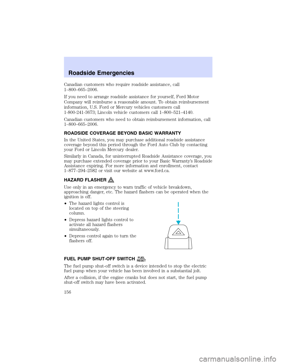
•The hazard lights control is
located on top of the steering
column.
•Depress hazard lights control to
activate all hazard flashers
simultaneously.
•Depress control again to turn the
flashers off.
FUEL PUMP SHUT-OFF SWITCH
FUEL
RESET
The fuel pump shut-off switch is a device intended to stop the electric
fuel pump when your vehicle has been involved in a substantial jolt.
After a collision, if the engine cranks but does not start, the fuel pump
shut-off switch may have been activated.
Roadside Emergencies
156
Page 157 of 240

If your vehicle is a sedan, the fuel
pump shut-off switch is located on
the right side of the trunk behind
the trunk liner.
If your vehicle is a wagon, the fuel
pump shut-off switch is located
behind the service panel on the
right side of the cargo area.
Use the following procedure to reset the fuel pump shut-off switch.
1. Turn the ignition to the OFF position.
2. Check the fuel system for leaks.
3. If no fuel leak is apparent, reset the fuel pump shut-off switch by
pushing in on the reset button.
4. Turn the ignition to the ON position. Pause for a few seconds and
return the key to the OFF position.
5. Make a further check for leaks in the fuel system.
Roadside Emergencies
157
Page 158 of 240
FUSES AND RELAYS
Fuses
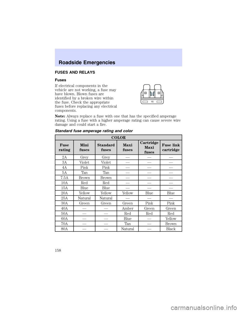
If electrical components in the
vehicle are not working, a fuse may
have blown. Blown fuses are
identified by a broken wire within
the fuse. Check the appropriate
fuses before replacing any electrical
components.
Note:Always replace a fuse with one that has the specified amperage
rating. Using a fuse with a higher amperage rating can cause severe wire
damage and could start a fire.
Standard fuse amperage rating and color
COLOR
Fuse
ratingMini
fusesStandard
fusesMaxi
fusesCartridge
Maxi
fusesFuse link
cartridge
2A Grey Grey———
3A Violet Violet———
4A Pink Pink———
5A Tan Tan———
7.5A Brown Brown———
10A Red Red———
15A Blue Blue———
20A Yellow Yellow Yellow Blue Blue
25A Natural Natural———
30A Green Green Green Pink Pink
40A——Amber Green Green
50A——Red Red Red
60A——Blue—Yellow
70A——Ta n—Brown
80A——Natural—Black
15
Roadside Emergencies
158
Page 159 of 240
Passenger compartment fuse panel
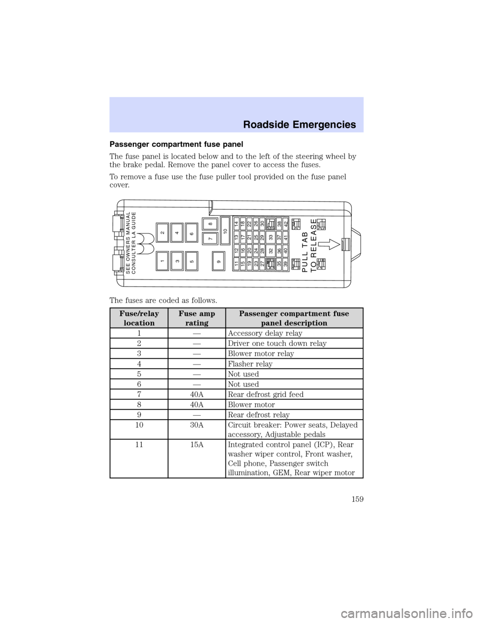
The fuse panel is located below and to the left of the steering wheel by
the brake pedal. Remove the panel cover to access the fuses.
To remove a fuse use the fuse puller tool provided on the fuse panel
cover.
The fuses are coded as follows.
Fuse/relay
locationFuse amp
ratingPassenger compartment fuse
panel description
1—Accessory delay relay
2—Driver one touch down relay
3—Blower motor relay
4—Flasher relay
5—Not used
6—Not used
7 40A Rear defrost grid feed
8 40A Blower motor
9—Rear defrost relay
10 30A Circuit breaker: Power seats, Delayed
accessory, Adjustable pedals
11 15A Integrated control panel (ICP), Rear
washer wiper control, Front washer,
Cell phone, Passenger switch
illumination, GEM, Rear wiper motor
12
34
56
78
9
10
11 1213 14
15
16 1718
19 2021 22
2324
2526
27 2829
30
32 33
35
3637
38
39 40
41
42
PULL TAB
TO RELEASE SEE OWNERS MANUAL
CONSULTER LA GUIDE
Roadside Emergencies
159
Page 160 of 240
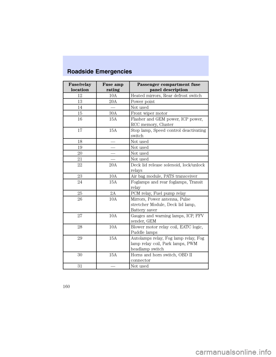
Fuse/relay
locationFuse amp
ratingPassenger compartment fuse
panel description
12 10A Heated mirrors, Rear defrost switch
13 20A Power point
14—Not used
15 30A Front wiper motor
16 15A Flasher and GEM power, ICP power,
RCC memory, Cluster
17 15A Stop lamp, Speed control deactivating
switch
18—Not used
19—Not used
20—Not used
21—Not used
22 20A Deck lid release solenoid, lock/unlock
relays
23 10A Air bag module, PATS transceiver
24 15A Foglamps and rear foglamps, Transit
relay
25 2A PCM relay, Fuel pump relay
26 10A Mirrors, Power antenna, Pulse
stretcher Module, Deck lid lamp,
Battery saver
27 10A Gauges and warning lamps, ICP, FFV
sender, GEM
28 10A Blower motor relay coil, EATC logic,
Puddle lamps
29 15A Autolamps relay, Fog lamp relay, Fog
lamp relay coil, Park lamps, PWM
headlamp switch
30 15A Horns and horn switch, OBD II
connector
31—Not used
Roadside Emergencies
160