heating Mercury Sable 2002 Owner's Manuals
[x] Cancel search | Manufacturer: MERCURY, Model Year: 2002, Model line: Sable, Model: Mercury Sable 2002Pages: 240, PDF Size: 3.53 MB
Page 1 of 240
Introduction 4
Instrument Cluster 10
Warning and control lights 10
Gauges 15
Entertainment Systems 18
AM/FM stereo cassette 18
AM/FM stereo with CD 24
CD changer 30
Climate Controls 35
Manual heating and air conditioning 35
Electronic automatic temperature control 38
Lights 46
Headlamps 46
Turn signal control 49
Bulb replacement 51
Driver Controls 62
Windshield wiper/washer control 62
Steering wheel adjustment 64
Power windows 65
Mirrors 66
Speed control (Cruise control) 69
Locks and Security 80
Keys 80
Locks 80
Anti-theft system 81
Table of Contents
1
Page 15 of 240
Headlamps on warning chime
Sounds when the headlamps or parking lamps are on, the key is removed
from the ignition and the driver’s door is opened.
Key-in-ignition warning chime
Sounds when the key is left in the ignition and the driver’s door is
opened.
Park brake warning chime
Sounds when the parking brake is set, the engine is running and the
transaxle is not in P (Park) or N (Neutral). The chime will shut off when
the parking brake is disengaged.
GAUGES
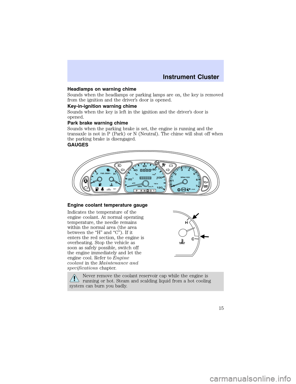
Engine coolant temperature gauge
Indicates the temperature of the
engine coolant. At normal operating
temperature, the needle remains
within the normal area (the area
between the“H”and“C”). If it
enters the red section, the engine is
overheating. Stop the vehicle as
soon as safely possible, switch off
the engine immediately and let the
engine cool. Refer toEngine
coolantin theMaintenance and
specificationschapter.
Never remove the coolant reservoir cap while the engine is
running or hot. Steam and scalding liquid from a hot cooling
system can burn you badly.
P!
BRAKE
+ –
CRUISE
RPMx1000
ABS0 123
4
5
6
7
204060
80
100
1202060
140
180
P R N D D 1MPH km/h
000000
0000
EFC H
FUEL DOOR >
THEFT LOW
COOLANTCRUISE
C H
Instrument Cluster
15
Page 35 of 240
MANUAL HEATING AND AIR CONDITIONING SYSTEM
(IF EQUIPPED)
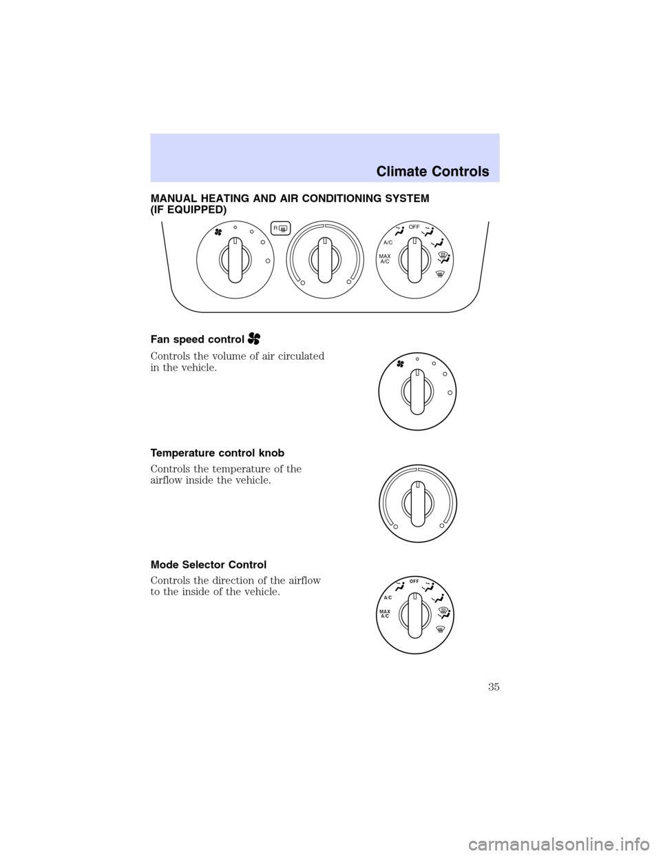
Fan speed control
Controls the volume of air circulated
in the vehicle.
Temperature control knob
Controls the temperature of the
airflow inside the vehicle.
Mode Selector Control
Controls the direction of the airflow
to the inside of the vehicle.
R
A/C
MAX
A/COFF
A/C
Climate Controls
35
Page 36 of 240
The air conditioning compressor can operate in all modes except
and. However, the air conditioning will only function if the outside
temperature is about 6°C (43°F) or higher.
Since the air conditioner removes considerable moisture from the air
during operation, it is normal if clear water drips on the ground under
the air conditioner drain while the system is working and even after you
have stopped the vehicle.
•MAX A/C–Uses recirculated air to cool the vehicle. MAX A/C is
noisier than A/C but more economical and will cool the inside of the
vehicle faster. Airflow will be from the instrument panel registers. This
mode can also be used to prevent undesirable odors from entering the
vehicle.
•A/C–Uses outside air to cool the vehicle. It is quieter than MAX A/C
but not as economical. Airflow will be from the instrument panel
registers.
•
(Panel)–Distributes outside air through the instrument panel
registers. However, the air will not be cooled below the outside
temperature because the air conditioning does not operate in this
mode.
•OFF–Outside air is shut out and the fan will not operate. For short
periods of time only, use this mode to prevent undesirable odors from
entering the vehicle.
•
(Panel and floor)–Distributes outside air through the
instrument panel registers and the floor ducts. Heating and air
conditioning capabilities are provided in this mode. For added
customer comfort, when the temperature control knob is anywhere in
between the full hot and full cold positions, the air distributed through
the floor ducts will be slightly warmer than the air sent to the
instrument panel registers.
•
(Floor)–Distributes outside air through the floor ducts.
However, the air will not be cooled below the outside temperature
because the air conditioning does not operate in this mode.
•
(Floor and defrost)–Distributes outside air through the
windshield defroster ducts and the floor ducts. Heating and air
conditioning capabilities are provided in this mode. For added
customer comfort, the air distributed through the floor ducts will be
slightly warmer than the air sent to the windshield defroster ducts. If
the temperature is about 6°C (43°F) or higher, the air conditioner will
automatically dehumidify the air to reduce fogging.
Climate Controls
36
Page 40 of 240
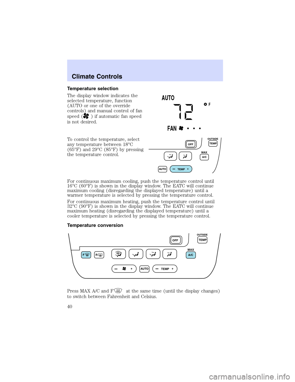
Temperature selection
The display window indicates the
selected temperature, function
(AUTO or one of the override
controls) and manual control of fan
speed (
) if automatic fan speed
is not desired.
To control the temperature, select
any temperature between 18°C
(65°F) and 29°C (85°F) by pressing
the temperature control.
For continuous maximum cooling, push the temperature control until
16°C (60°F) is shown in the display window. The EATC will continue
maximum cooling (disregarding the displayed temperature) until a
warmer temperature is selected by pressing the temperature control.
For continuous maximum heating, push the temperature control until
32°C (90°F) is shown in the display window. The EATC will continue
maximum heating (disregarding the displayed temperature) until a
cooler temperature is selected by pressing the temperature control.
Temperature conversion
Press MAX A/C and F
at the same time (until the display changes)
to switch between Fahrenheit and Celsius.
F
AUTO
FAN• • •
AUTO
TEMPOFF
MAX
A/CTEMP
OUTSIDE
F
R
AUTO
TEMPOFFTEMP
MAX
A/C
OUTSIDE
Climate Controls
40
Page 42 of 240
However, the air conditioning will only function if the outside
temperature is about 6°C (43°F) or higher.
Since the air conditioner removes considerable moisture from the air
during operation, it is normal if clear water drips on the ground under
the air conditioner drain while the system is working and even after you
have stopped the vehicle.
•F
- Distributes outside air through the windshield defroster
ducts. It can be used to clear ice or fog from the windshield. If the
outside air temperature is about 6°C (43°F) or higher, the air
conditioner will automatically dehumidify the air to reduce fogging.
•
R(Rear Window Defroster)—Refer toRear Window Defroster.
•
(Floor and defrost) - Distributes outside air through the
windshield defroster ducts and the floor ducts. Heating and air
conditioning capabilities are provided in this mode. The air will be
heated or cooled based on the temperature selection. For added
customer comfort, the air distributed through the floor ducts will be
slightly warmer than the air sent to the windshield defroster ducts. If
the temperature is about 6°C (43°F) or higher, the air conditioner will
automatically dehumidify the air to reduce fogging.
•
(Floor) - Distributes outside air through the floor ducts. Heating
and air conditioning capabilities are provided in this mode. The air will
be heated or cooled based on temperature selection.
•
(Panel and floor) - Distributes outside air through the instrument
panel registers and the floor ducts. Heating and air conditioning
capabilities are provided in this mode. The air will be heated or cooled
based on the temperature selection. For added customer comfort, the
air distributed through the floor ducts will be slightly warmer than the
air sent to the instrument panel registers.
•
(Panel) - Distributes outside air through the instrument panel
registers. However, the air cannot be cooled below the outside
temperature because the air conditioning does not operate in this
mode.
•MAX A/C - Uses recirculated air to cool the vehicle. The temperature
will remain unchanged and air will be cooled based on the selected
temperature. To exit, press AUTOMATIC or any other override
controls. MAX A/C is noisier than normal A/C but more economical
and will cool the inside of the vehicle faster. Airflow is from the
instrument panel registers. This mode can also be used to prevent
undesirable odors from entering the vehicle.
Climate Controls
42
Page 139 of 240
Have the exhaust and body ventilation systems checked whenever:
•the vehicle is raised for service.
•the sound of the exhaust system changes.
•the vehicle has been damaged in a collision.
WARNING:Engine exhaust, some of its constituents, and
certain vehicle components contain or emit chemicals known to
the State of California to cause cancer and birth defects or other
reproductive harm. In addition, certain fluids contained in vehicles and
certain products of component wear contain or emit chemicals known
to the State of California to cause cancer and birth defects or other
reproductive harm.
Important ventilating information
If the engine is idling while the vehicle is stopped in an open area for
long periods of time, open the windows at least 2.5 cm (one inch).
Adjust the heating or air conditioning (if equipped) to bring in fresh air.
Improve vehicle ventilation by keeping all air inlet vents clear of snow,
leaves and other debris.
BRAKES
Your service brakes are self-adjusting. Refer to the scheduled
maintenance guide for scheduled maintenance.
Occasional brake noise is normal and often does not indicate a
performance concern with the vehicle’s brake system. In normal
operation, automotive brake systems may emit occasional or intermittent
squeal or groan noises when the brakes are applied. Such noises are
usually heard during the first few brake applications in the morning;
however, they may be heard at any time while braking and can be
aggravated by environmental conditions such as cold, heat, moisture,
road dust, salt or mud. If a“metal-to-metal,”“continuous grinding”or
“continuous squeal”sound is present while braking, the brake linings
may be worn-out and should be inspected by a qualified service
technician.
If you are driving down a long or steep hill, shift to a lower gear.
Do not apply your brakes continuously, as they may overheat
and become less effective.
Driving
139
Page 202 of 240
Do not put engine coolant in the windshield washer fluid
container. If sprayed on the windshield, engine coolant could
make it difficult to see through the windshield.
The cooling system in your vehicle is filled with either green-colored
Motorcraft Premium Engine Coolant meeting Ford specification
ESE-M97B44–A or yellow-colored Motorcraft Premium Gold Engine
Coolant meeting Ford Specification WSS-M97B51–A1. To determine your
vehicle’s coolant type (color), check your coolant reservoir.
•Add Motorcraft Premium Engine Coolant (green-colored),
VC-4–A (U.S.) or CXC-10 (Canada) or Motorcraft Premium
Gold Engine Coolant (yellow-colored), VC-7–A (VC-7–Bin
Oregon), depending on the type of coolant originally equipped
in your vehicle.If you are unsure which type of coolant your vehicle
requires, check your coolant reservoir or contact your local dealer.
Note:Use of Motorcraft Cooling System Stop Leak Pellets, VC-6,
darkens the color of Motorcraft Premium Gold Engine Coolant from
yellow to golden tan.
•Do not add/mix an orange-colored, extended life coolant such
as Motorcraft Speciality Orange Engine Coolant, VC-2 (US) or
CXC-209 (Canada), meeting Ford specification WSS-M97B44–D
with the factory-filled coolant.Mixing Motorcraft Speciality Orange
Engine Coolant or any orange-colored extended life product with your
factory filled coolant can result in degraded corrosion protection.
•A large amount of water without engine coolant may be added, in case
of emergency, to reach a vehicle service location. In this instance, the
cooling system must be drained and refilled with a 50/50 mixture of
engine coolant and distilled water as soon as possible. Water alone
(without engine coolant) can cause engine damage from corrosion,
overheating or freezing.
•Do not use alcohol, methanol, brine or any engine coolants
mixed with alcohol or methanol antifreeze (coolant).Alcohol
and other liquids can cause engine damage from overheating or
freezing.
•Do not add extra inhibitors or additives to the coolant.These
can be harmful and compromise the corrosion protection of the engine
coolant.
•Do not mix with recycled coolant unless from a Ford-approved
recycling process (seeUse of Recycled engine coolantsection).
Maintenance and Specifications
202
Page 203 of 240
For vehicles with overflow coolant systems with a non-pressurized cap
on the coolant recovery system, add coolant to the coolant recovery
reservoir when the engine is cool. Add the proper mixture of coolant and
water to the“cold full”level. For all other vehicles, which have a coolant
degas system with a pressurized cap, or if it is necessary to remove the
coolant pressure relief cap on the radiator of a vehicle with an overflow
system, follow these steps to add engine coolant.
To reduce the risk of personal injury, make sure the engine is
cool before unscrewing the coolant pressure relief cap. The
cooling system is under pressure; steam and hot liquid can come out
forcefully when the cap is loosened slightly.
1. Before you begin, turn the engine off and let it cool.
2. When the engine is cool, wrap a thick cloth around the coolant
pressure relief cap on the coolant reservoir (an opaque plastic bottle).
Slowly turn cap counterclockwise (left) until pressure begins to release.
3. Step back while the pressure releases.
4. When you are sure that all the pressure has been released, use the
cloth to turn it counterclockwise and remove the cap.
5. Fill the coolant reservoir slowly with the proper coolant mixture (see
above), to within the“cold fill range”or the“cold full”level on the
reservoir. If you removed the radiator cap in an overflow system, fill the
radiator until the coolant is visible and radiator is almost full.
6. Replace the cap. Turn until tightly installed. (Cap must be tightly
installed to prevent coolant loss.)
After any coolant has been added, check the coolant concentration, refer
toChecking Engine Coolantsection. If the concentration is not 50/50
(protection to–34°F/–36°C), drain some coolant and adjust the
concentration. It may take several drains and additions to obtain a 50/50
coolant concentration.
Whenever coolant has been added, the coolant level in the coolant
reservoir should be checked the next few times you drive the vehicle. If
necessary, add enough 50/50 concentration of engine coolant and
distilled water to bring the liquid level to the proper level.
If you have to add more than 1.0 liter (1.0 quart) of engine coolant per
month, have your dealer check the engine cooling system. Your cooling
system may have a leak. Operating an engine with a low level of coolant
can result in engine overheating and possible engine damage.
Maintenance and Specifications
203
Page 219 of 240
3. With the parking brake engaged and your foot on the brake pedal,
start the engine and move the gearshift lever through all of the gear
ranges. Allow sufficient time for each gear to engage.
4. Latch the gearshift lever in P (Park) and leave the engine running.
5. Remove the dipstick, wiping it clean with a clean, dry lint free rag. If
necessary, refer toIdentifying components in the engine compartment
in this chapter for the location of the dipstick.
6. Install the dipstick making sure it is fully seated in the filler tube.
7. Remove the dipstick and inspect the fluid level. The fluid should be in
the designated areas for normal operating temperature.
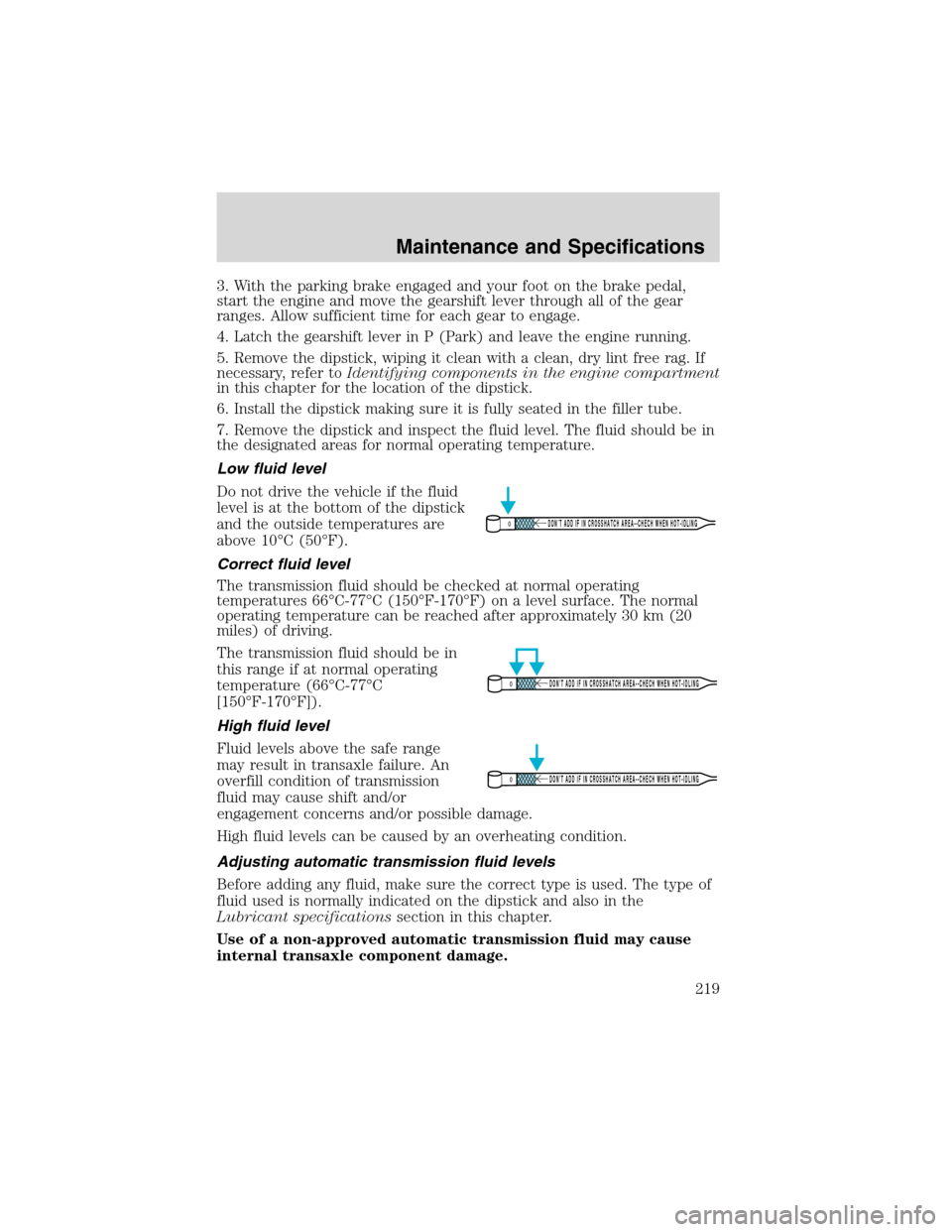
Low fluid level
Do not drive the vehicle if the fluid
level is at the bottom of the dipstick
and the outside temperatures are
above 10°C (50°F).
Correct fluid level
The transmission fluid should be checked at normal operating
temperatures 66°C-77°C (150°F-170°F) on a level surface. The normal
operating temperature can be reached after approximately 30 km (20
miles) of driving.
The transmission fluid should be in
this range if at normal operating
temperature (66°C-77°C
[150°F-170°F]).
High fluid level
Fluid levels above the safe range
may result in transaxle failure. An
overfill condition of transmission
fluid may cause shift and/or
engagement concerns and/or possible damage.
High fluid levels can be caused by an overheating condition.
Adjusting automatic transmission fluid levels
Before adding any fluid, make sure the correct type is used. The type of
fluid used is normally indicated on the dipstick and also in the
Lubricant specificationssection in this chapter.
Use of a non-approved automatic transmission fluid may cause
internal transaxle component damage.
DON’T ADD IF IN CROSSHATCH AREA--CHECH WHEN HOT-IDLING
DON’T ADD IF IN CROSSHATCH AREA--CHECH WHEN HOT-IDLING
DON’T ADD IF IN CROSSHATCH AREA--CHECH WHEN HOT-IDLING
Maintenance and Specifications
219