Mercury Villager 1999 Owner's Manuals
Manufacturer: MERCURY, Model Year: 1999, Model line: Villager, Model: Mercury Villager 1999Pages: 264, PDF Size: 2.19 MB
Page 201 of 264
To avoid scalding hot steam or coolant from being released from
the engine cooling system, never remove the radiator cap while
the engine is running or hot. Failure to follow this warning may result
in damage to the engine's cooling system and possible severe personal
injury.
If you must remove the radiator cap, follow these steps to avoid personal
injury:
1. Before you remove the cap, turn the engine off and let it cool.
2. When the engine is cool, wrap a thick cloth around the cap. Slowly
turn cap counterclockwise until pressure begins to release.
3. Step back while the pressure releases.
4. When you are sure that all the pressure has been released, use the
cloth to turn it counterclockwise and remove the cap.
Recycled engine coolant
Ford Motor Company recommends the use of recycled engine coolant
produced by Ford-approved processes.
Not all coolant recycling processes produce coolant which meets Ford
specification ESE-M97B44-A, and use of such coolant may harm engine
and cooling system components.
Always dispose of used automotive fluids in a responsible manner.
Follow your community's regulations and standards for recycling and
disposing of automotive fluids.
Coolant refill capacity
To find out how much fluid your vehicle's cooling system can hold, refer
toRefill capacitiesin theCapacities and specificationschapter.
Fill your engine coolant reservoir as outlined inAdding engine coolant
in this chapter.
Severe winter climate
If you drive in extremely cold climates (less than ±36ÉC [±34ÉF]), it may
be necessary to increase the coolant concentration above 50%. Refer to
the chart on the coolant container to ensure the coolant concentration in
your vehicle is such that the coolant will not freeze at the temperature
level in which you drive during winter months.
Maintenance and care
201
Page 202 of 264
²NEVER increase the coolant concentration above 60%.
²Increased engine coolant concentrations above 60% will
decrease the freeze protection characteristics of the engine
coolant and may cause engine damage.
Vehicles driven year-round in non-extreme climates should use a 50/50
mixture of engine coolant and distilled water for optimum freeze
protection.
CHECKING AND ADDING POWER STEERING FLUID
Check the power steering fluid. Refer to the Scheduled Maintenance
Guide for the service interval schedules. If adding fluid is necessary, use
only MERCONtAT F.
1. Start the engine and let it run
until it reaches normal operating
temperature (the engine coolant
temperature gauge indicator will be
near the center of the normal area
between H and C).
2. While the engine idles, turn the
steering wheel left and right several
times.
3. Turn the engine off.
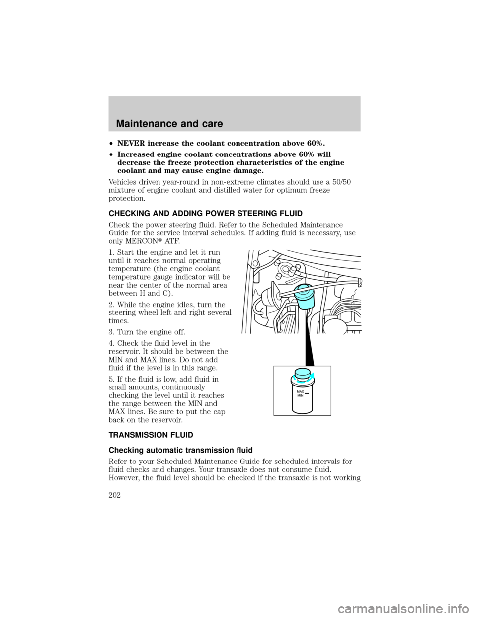
4. Check the fluid level in the
reservoir. It should be between the
MIN and MAX lines. Do not add
fluid if the level is in this range.
5. If the fluid is low, add fluid in
small amounts, continuously
checking the level until it reaches
the range between the MIN and
MAX lines. Be sure to put the cap
back on the reservoir.
TRANSMISSION FLUID
Checking automatic transmission fluid
Refer to your Scheduled Maintenance Guide for scheduled intervals for
fluid checks and changes. Your transaxle does not consume fluid.
However, the fluid level should be checked if the transaxle is not working
MAX
MIN
Maintenance and care
202
Page 203 of 264
properly, i.e., if the transaxle slips or shifts slowly or if you notice some
sign of fluid leakage.
Automatic transmission fluid expands when warmed. To obtain an
accurate fluid check, drive the vehicle until it is warmed up
(approximately 30 km [20 miles]). If your vehicle has been
operated for an extended period at high speeds, in city traffic
during hot weather or pulling a trailer, the vehicle should be
turned off for about 30 minutes to allow fluid to cool before
checking.
1. Drive the vehicle 30 km (20 miles) or until it reaches normal operating
temperature.
2. Park the vehicle on a level surface and engage the parking brake.
3. With the parking brake engaged and your foot on the brake pedal,
start the engine and move the gearshift lever through all of the gear
ranges. Allow sufficient time for each gear to engage.
4. Latch the gearshift lever in P (Park) and leave the engine running.
5. Remove the dipstick, wiping it clean with a clean, dry lint free rag.
6. Install the dipstick making sure it is fully seated in the filler tube.
7. Remove the dipstick and inspect the fluid level. The fluid should be in
the designated areas for normal operating temperature.
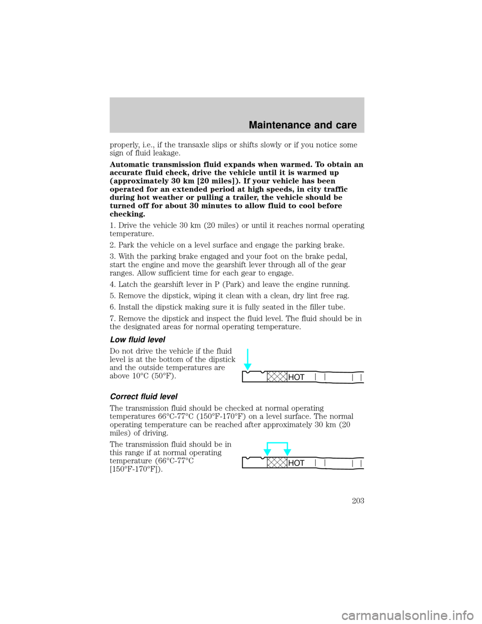
Low fluid level
Do not drive the vehicle if the fluid
level is at the bottom of the dipstick
and the outside temperatures are
above 10ÉC (50ÉF).
Correct fluid level
The transmission fluid should be checked at normal operating
temperatures 66ÉC-77ÉC (150ÉF-170ÉF) on a level surface. The normal
operating temperature can be reached after approximately 30 km (20
miles) of driving.
The transmission fluid should be in
this range if at normal operating
temperature (66ÉC-77ÉC
[150ÉF-170ÉF]).
HOT
HOT
Maintenance and care
203
Page 204 of 264
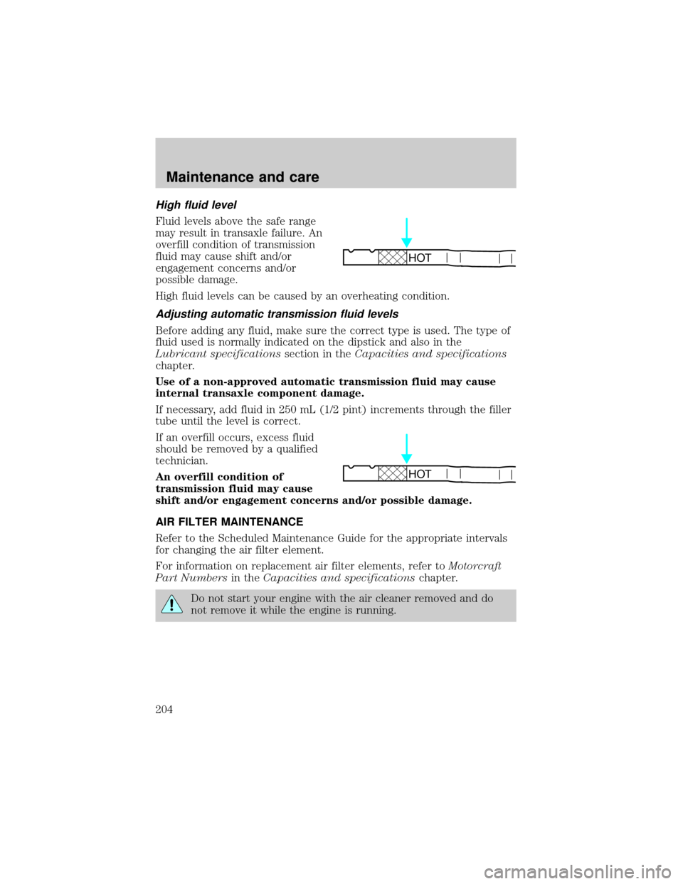
High fluid level
Fluid levels above the safe range
may result in transaxle failure. An
overfill condition of transmission
fluid may cause shift and/or
engagement concerns and/or
possible damage.
High fluid levels can be caused by an overheating condition.
Adjusting automatic transmission fluid levels
Before adding any fluid, make sure the correct type is used. The type of
fluid used is normally indicated on the dipstick and also in the
Lubricant specificationssection in theCapacities and specifications
chapter.
Use of a non-approved automatic transmission fluid may cause
internal transaxle component damage.
If necessary, add fluid in 250 mL (1/2 pint) increments through the filler
tube until the level is correct.
If an overfill occurs, excess fluid
should be removed by a qualified
technician.
An overfill condition of
transmission fluid may cause
shift and/or engagement concerns and/or possible damage.
AIR FILTER MAINTENANCE
Refer to the Scheduled Maintenance Guide for the appropriate intervals
for changing the air filter element.
For information on replacement air filter elements, refer toMotorcraft
Part Numbersin theCapacities and specificationschapter.
Do not start your engine with the air cleaner removed and do
not remove it while the engine is running.
HOT
HOT
Maintenance and care
204
Page 205 of 264
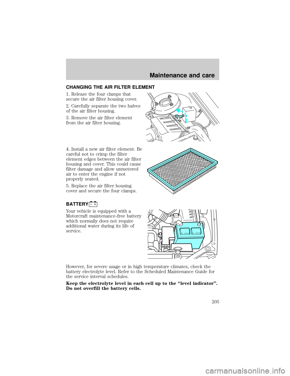
CHANGING THE AIR FILTER ELEMENT
1. Release the four clamps that
secure the air filter housing cover.
2. Carefully separate the two halves
of the air filter housing.
3. Remove the air filter element
from the air filter housing.
4. Install a new air filter element. Be
careful not to crimp the filter
element edges between the air filter
housing and cover. This could cause
filter damage and allow unmetered
air to enter the engine if not
properly seated.
5. Replace the air filter housing
cover and secure the four clamps.
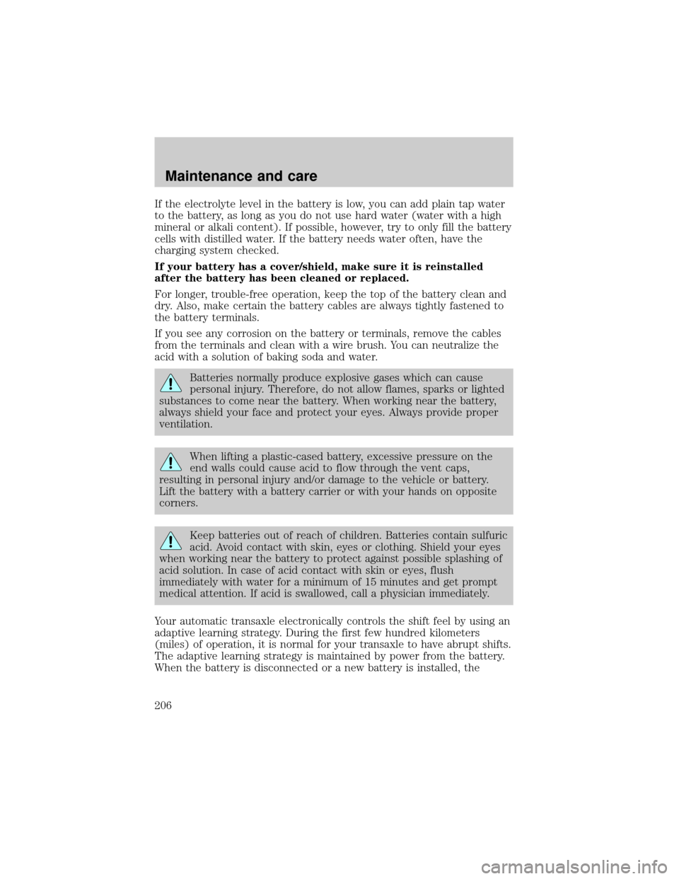
BATTERY
Your vehicle is equipped with a
Motorcraft maintenance-free battery
which normally does not require
additional water during its life of
service.
However, for severe usage or in high temperature climates, check the
battery electrolyte level. Refer to the Scheduled Maintenance Guide for
the service interval schedules.
Keep the electrolyte level in each cell up to the ªlevel indicatorº.
Do not overfill the battery cells.
Maintenance and care
205
Page 206 of 264
If the electrolyte level in the battery is low, you can add plain tap water
to the battery, as long as you do not use hard water (water with a high
mineral or alkali content). If possible, however, try to only fill the battery
cells with distilled water. If the battery needs water often, have the
charging system checked.
If your battery has a cover/shield, make sure it is reinstalled
after the battery has been cleaned or replaced.
For longer, trouble-free operation, keep the top of the battery clean and
dry. Also, make certain the battery cables are always tightly fastened to
the battery terminals.
If you see any corrosion on the battery or terminals, remove the cables
from the terminals and clean with a wire brush. You can neutralize the
acid with a solution of baking soda and water.
Batteries normally produce explosive gases which can cause
personal injury. Therefore, do not allow flames, sparks or lighted
substances to come near the battery. When working near the battery,
always shield your face and protect your eyes. Always provide proper
ventilation.
When lifting a plastic-cased battery, excessive pressure on the
end walls could cause acid to flow through the vent caps,
resulting in personal injury and/or damage to the vehicle or battery.
Lift the battery with a battery carrier or with your hands on opposite
corners.
Keep batteries out of reach of children. Batteries contain sulfuric
acid. Avoid contact with skin, eyes or clothing. Shield your eyes
when working near the battery to protect against possible splashing of
acid solution. In case of acid contact with skin or eyes, flush
immediately with water for a minimum of 15 minutes and get prompt
medical attention. If acid is swallowed, call a physician immediately.
Your automatic transaxle electronically controls the shift feel by using an
adaptive learning strategy. During the first few hundred kilometers
(miles) of operation, it is normal for your transaxle to have abrupt shifts.
The adaptive learning strategy is maintained by power from the battery.
When the battery is disconnected or a new battery is installed, the
Maintenance and care
206
Page 207 of 264
transaxle must relearn its adaptive strategy. Optimal shifting will resume
within a few hundred kilometers (miles) of operation.
If the battery has been disconnected or a new battery has been installed,
the clock and the preset radio stations must be reset once the battery is
reconnected.
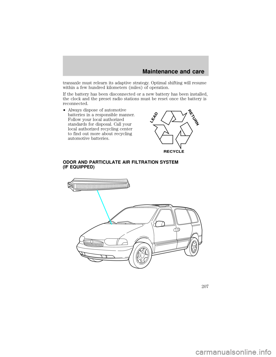
²Always dispose of automotive
batteries in a responsible manner.
Follow your local authorized
standards for disposal. Call your
local authorized recycling center
to find out more about recycling
automotive batteries.
ODOR AND PARTICULATE AIR FILTRATION SYSTEM
(IF EQUIPPED)
LEAD
RETURN
RECYCLE
Maintenance and care
207
Page 208 of 264

The odor and particulate air filtration system is designed to reduce the
concentration of objectionable exterior odors as well as airborne particles
such as dust, spores and pollen in the air being supplied to the interior
of the vehicle. The extent of EXTERIOR odor reduction depends on the
odor itself and the perceptional threshold of the individual. The odor and
particulate filtration system gives the following benefits to customers:
²Improves the customer's driving comfort by reducing odor and particle
concentration
²Improves the interior compartment cleanliness
²Protects the climate control components from particle deposits
The filter is located just in front of the windshield under the cowl grille
on the passenger side of the vehicle.
To replace the filter, perform the following procedure:
1. Remove both windshield wiper
arms.
²Lift the wiper arm away from the
windshield surface until the wiper
arm is perpendicular to the
windshield surface.
²Rotate the small retaining clip at
the base of the wiper arm
counterclockwise while holding
the wiper arm.
²Lift and remove the wiper arm
while holding the retaining clip
outward. Note the LH and RH
wiper arms.
Maintenance and care
208
Page 209 of 264

2. Remove the six (6) screws (B) from the cowl grille (A) at the base of
the windshield.
3. Open the hood.
4. Remove the four (4) plastic screws (C) from the forward edge of the
cowl leaf screen under the hood.
²Remove the four (4) screw anchors by pushing upward on the screw
anchor.
5. Disconnect the windshield washer
hose at the Y connector at the rear
corner of the engine compartment.
6. Lift the cowl grille from the vehicle.
7. Locate the cabin air filter on the passenger side of the vehicle.
A
B
C
Maintenance and care
209
Page 210 of 264

8. Remove four (4) screws from the top surface of the cabin air filter top
cover.
9. Remove the cover.
10. Remove the filter element by
pulling forward on the top surface of
the filter and lifting.
11. Install the new filter (A)
element into the filter retaining
frame (B). Ensure that you insert
the three retaining tabs in the
bottom of the filter frame.
12. Reinstall the filter top cover and
the four (4) screws.
13. Reconnect the washer hose.
A
B
Maintenance and care
210