battery Mercury Villager 1999 Owner's Manuals
[x] Cancel search | Manufacturer: MERCURY, Model Year: 1999, Model line: Villager, Model: Mercury Villager 1999Pages: 264, PDF Size: 2.19 MB
Page 6 of 264
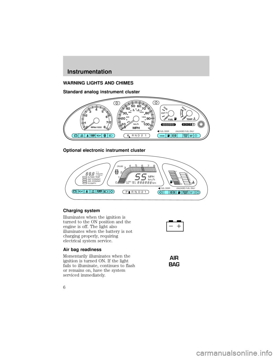
WARNING LIGHTS AND CHIMES
Standard analog instrument cluster
Optional electronic instrument cluster
Charging system
Illuminates when the ignition is
turned to the ON position and the
engine is off. The light also
illuminates when the battery is not
charging properly, requiring
electrical system service.
Air bag readiness
Momentarily illuminates when the
ignition is turned ON. If the light
fails to illuminate, continues to flash
or remains on, have the system
serviced immediately.
CE
F
H1/2
FUELTEMP
NORMAL
0
PRND2P1P!
BRAKEAIR
BAGSERVICE
ENGINE
SOONCRUISEO/D
OFF
00000
00000MPHkm/h10 20304050
60
70
80
90
10020 406080
100120
140
160
0 234
5
6
7
8RPMx10001
FUEL DOOR UNLEADED FUEL ONLY
SERVICE
ENGINE
SOONABSAIR
BAGABSO/D
OFF
OUTSIDE TEMP
INST ECONOMY
AVG. ECONOMY
TO EMPTY
PRND21FUEL DOOR UNLEADED FUEL ONLY CRUISE
MPH
km/h
km
F
EH
C
1/2N
O
R
M
A
L
012345
6
78
P!BRAKE
X 1000
RPMTRIP 1
TRIP 2 ˚F ˚C
MILES/BAL
L/100 km
AIR
BAG
Instrumentation
6
Page 100 of 264
MOON ROOF (IF EQUIPPED)
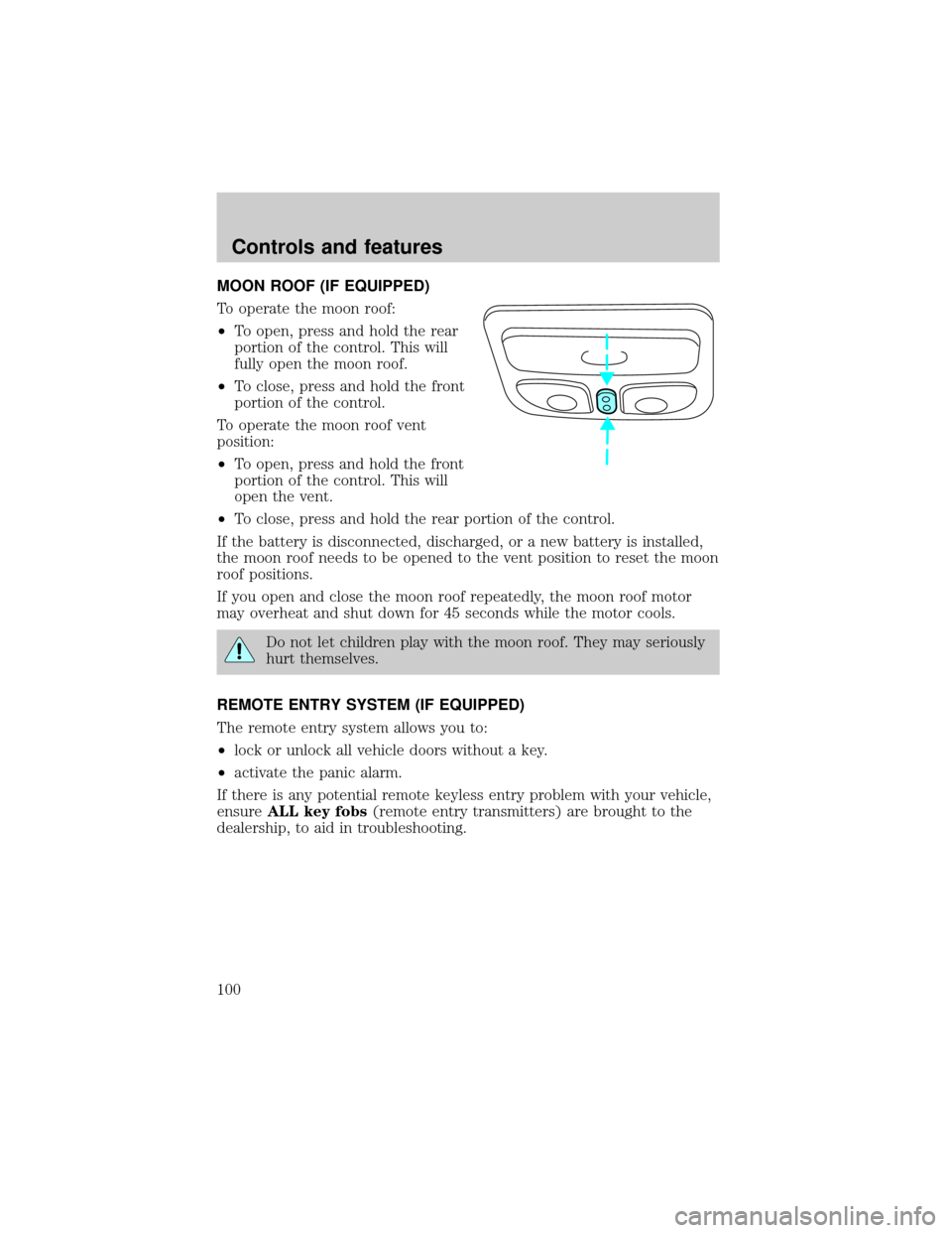
To operate the moon roof:
²To open, press and hold the rear
portion of the control. This will
fully open the moon roof.
²To close, press and hold the front
portion of the control.
To operate the moon roof vent
position:
²To open, press and hold the front
portion of the control. This will
open the vent.
²To close, press and hold the rear portion of the control.
If the battery is disconnected, discharged, or a new battery is installed,
the moon roof needs to be opened to the vent position to reset the moon
roof positions.
If you open and close the moon roof repeatedly, the moon roof motor
may overheat and shut down for 45 seconds while the motor cools.
Do not let children play with the moon roof. They may seriously
hurt themselves.
REMOTE ENTRY SYSTEM (IF EQUIPPED)
The remote entry system allows you to:
²lock or unlock all vehicle doors without a key.
²activate the panic alarm.
If there is any potential remote keyless entry problem with your vehicle,
ensureALL key fobs(remote entry transmitters) are brought to the
dealership, to aid in troubleshooting.
Controls and features
100
Page 102 of 264

This device complies with part 15 of the FCC rules and with RS-210 of
Industry Canada. Operation is subject to the following two conditions:
(1) This device may not cause harmful interference, and (2) This device
must accept any interference received, including interference that may
cause undesired operation.
Changes or modifications not expressly approved by the party
responsible for compliance could void the user's authority to
operate the equipment.
Illuminated entry
The interior lamps illuminate when the remote entry system is used to
unlock the door(s) or sound the panic alarm.
The system automatically turns off after 15 seconds or when the ignition
is turned to the RUN position.
The inside lights will not turn off if:
²they have been turned on with the headlamp control or
²any door is open.
The battery saver will shut off the interior lamps after 30 minutes if the
front door is left open or after 60 minutes if the liftgate is left open.
Illuminated exit
The interior lights will illuminate when the key is removed from the
ignition.
The system automatically turns off after 25 seconds or when the driver's
door is opened.
Replacing the battery
The transmitter is powered by one coin type three-volt lithium battery.
Typical operating range will allow you to be up to 10 meters (33 feet)
away from your vehicle. A decrease in operating range can be caused by:
²weather conditions
²nearby radio towers
²structures around the vehicle
²other vehicles parked next to the vehicle
Controls and features
102
Page 103 of 264
To replace the battery:
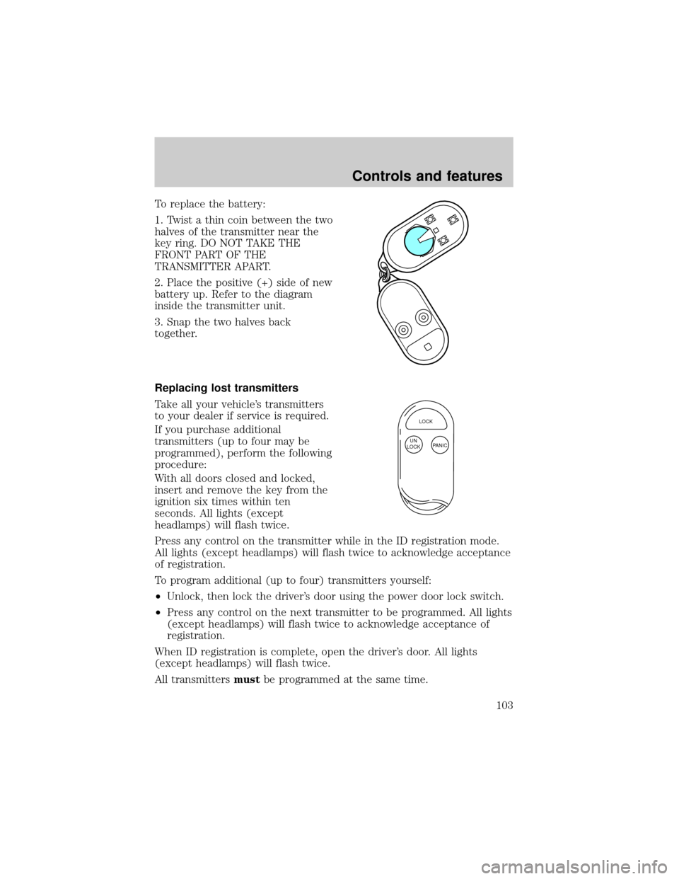
1. Twist a thin coin between the two
halves of the transmitter near the
key ring. DO NOT TAKE THE
FRONT PART OF THE
TRANSMITTER APART.
2. Place the positive (+) side of new
battery up. Refer to the diagram
inside the transmitter unit.
3. Snap the two halves back
together.
Replacing lost transmitters
Take all your vehicle's transmitters
to your dealer if service is required.
If you purchase additional
transmitters (up to four may be
programmed), perform the following
procedure:
With all doors closed and locked,
insert and remove the key from the
ignition six times within ten
seconds. All lights (except
headlamps) will flash twice.
Press any control on the transmitter while in the ID registration mode.
All lights (except headlamps) will flash twice to acknowledge acceptance
of registration.
To program additional (up to four) transmitters yourself:
²Unlock, then lock the driver's door using the power door lock switch.
²Press any control on the next transmitter to be programmed. All lights
(except headlamps) will flash twice to acknowledge acceptance of
registration.
When ID registration is complete, open the driver's door. All lights
(except headlamps) will flash twice.
All transmittersmustbe programmed at the same time.
LOCK
PANIC UN
LOCK
Controls and features
103
Page 161 of 264

Understanding gearshift positions
To account for customer driving habits and conditions, your automatic
transaxle electronically controls the shift feel by using an adaptive
learning strategy. During the first few hundred kilometers (miles) of
operation, it is normal for your transaxle to have abrupt shifts. The
adaptive learning strategy is maintained by power from the battery.
When the battery is disconnected or a new battery is installed, the
transaxle must relearn its adaptive strategy. Optimal shifting will resume
within a few hundred kilometers (miles) of operation.
P (Park)
Always come to a complete stop
before shifting into P (Park). Make
sure the gearshift is securely latched
in P (Park). This locks the transaxle and prevents the front wheels from
rotating.
Always set the parking brake fully and make sure the gearshift is
securely latched in P (Park).
Never leave your vehicle unattended while it is running.
R (Reverse)
With the gearshift in R (Reverse),
the vehicle will move backward. You
should always come to a complete
stop before shifting into and out of R (Reverse).
N (Neutral)
With the gearshift in the N
(Neutral) position, the vehicle can
be started and is free to roll. Hold
the brake pedal down while in this position.
Overdrive Ð column mounted gearshift with O/D off switch
The Overdrive position with the O/D
OFF switchnotdepressed is the
normal driving position for this
P RND21
P RND21
P RND21
P RND21
Driving
161
Page 164 of 264
Driving with an automatic overdrive transaxle
Your automatic transaxle electronically controls the shift feel by using an
adaptive learning strategy. This feature is designed to optimize shift
smoothness. It is normal for your transaxle to shift firmly during the first
few hundred kilometers (miles) of operation until the adaptive strategy
has been learned. The adaptive learning strategy is maintained by power
from the battery. When the battery is disconnected or a new battery is
installed, the transaxle must relearn its adaptive strategy. Optimal
shifting will resume within a few hundred kilometers (miles) of
operation.
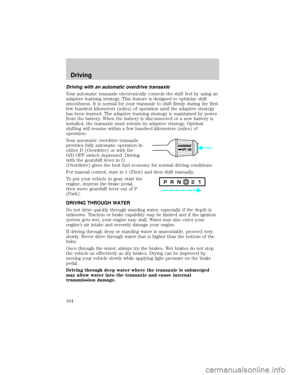
Your automatic overdrive transaxle
provides fully automatic operation in
either D (Overdrive) or with the
O/D OFF switch depressed. Driving
with the gearshift lever in D
(Overdrive) gives the best fuel economy for normal driving conditions.
For manual control, start in 1 (First) and then shift manually.
To put your vehicle in gear, start the
engine, depress the brake pedal,
then move gearshift lever out of P
(Park).
DRIVING THROUGH WATER
Do not drive quickly through standing water, especially if the depth is
unknown. Traction or brake capability may be limited and if the ignition
system gets wet, your engine may stall. Water may also enter your
engine's air intake and severely damage your engine.
If driving through deep or standing water is unavoidable, proceed very
slowly. Never drive through water that is higher than the bottom of the
hubs.
Once through the water, always try the brakes. Wet brakes do not stop
the vehicle as effectively as dry brakes. Drying can be improved by
moving your vehicle slowly while applying light pressure on the brake
pedal.
Driving through deep water where the transaxle is submerged
may allow water into the transaxle and cause internal
transmission damage.
OVERDRIVE
OFF/ON
P R N D 2 1
Driving
164
Page 167 of 264

The optional Trailer Tow Prep Package is recommended for towing of
any trailer since it provides a heavy duty battery, conventional size spare
tire and wiring.
Trailer towing puts additional loads on your vehicle's engine,
transmission, axle, brakes, tires, and suspension. For your safety and to
maximize vehicle performance, be sure to use the proper equipment
while towing.
Follow these guidelines to ensure safe towing procedure:
²Stay within your vehicle's load limits. If exceeded, cargo should be
removed from the trailer and/or the vehicle until all weights are within
specified limits.
²Thoroughly prepare your vehicle for towing. Refer toPreparing to
towin this chapter.
²Use extra caution when driving while trailer towing. Refer toDriving
while you towin this chapter.
²Service your vehicle more frequently if you tow a trailer. Refer to the
severe duty schedule in the Scheduled Maintenance Guide.
²Do not tow a trailer until your vehicle has been driven at least 800 km
(500 miles).
²Refer to the instructions included with towing accessories for the
proper installation and adjustment specifications.
Trailer Tow Prep Package (if equipped)
The trailer tow prep package on your vehicle (if equipped) includes:
²Heavy duty battery
²Conventional size spare tire
²Trailer tow module and jumper harness
Using the jumper harness (if equipped)
²Remove the connector cap from the vehicle harness located behind
the rear bumper. Store the connector cap in the glove box for
reinstallation.
²Connect the tow harness to the vehicle harness located behind the
rear bumper.
²Connect the tow harness connector (SAE J1239) to your trailer.
²Confirm the proper vehicle and trailer stop/turn lamp operation.
Driving
167
Page 176 of 264
Fuse/Relay
LocationFuse Amp
RatingDescription
Electron 10A Transmission Control, Lighting
Control Module, ABS Control
Module, Smart Entry Control
(SEC)/Timer Module
Rear Defog 20A Rear Window Defrost
Front Blower 20A Front Blower Motor, Front Blower
Motor/Speed Controller
Rear Defog 20A Rear Window Defrost
Ð Ð Not Used
Heated Mirror 10A Rear Window Defrost Switch,
Power/Heated Mirrors
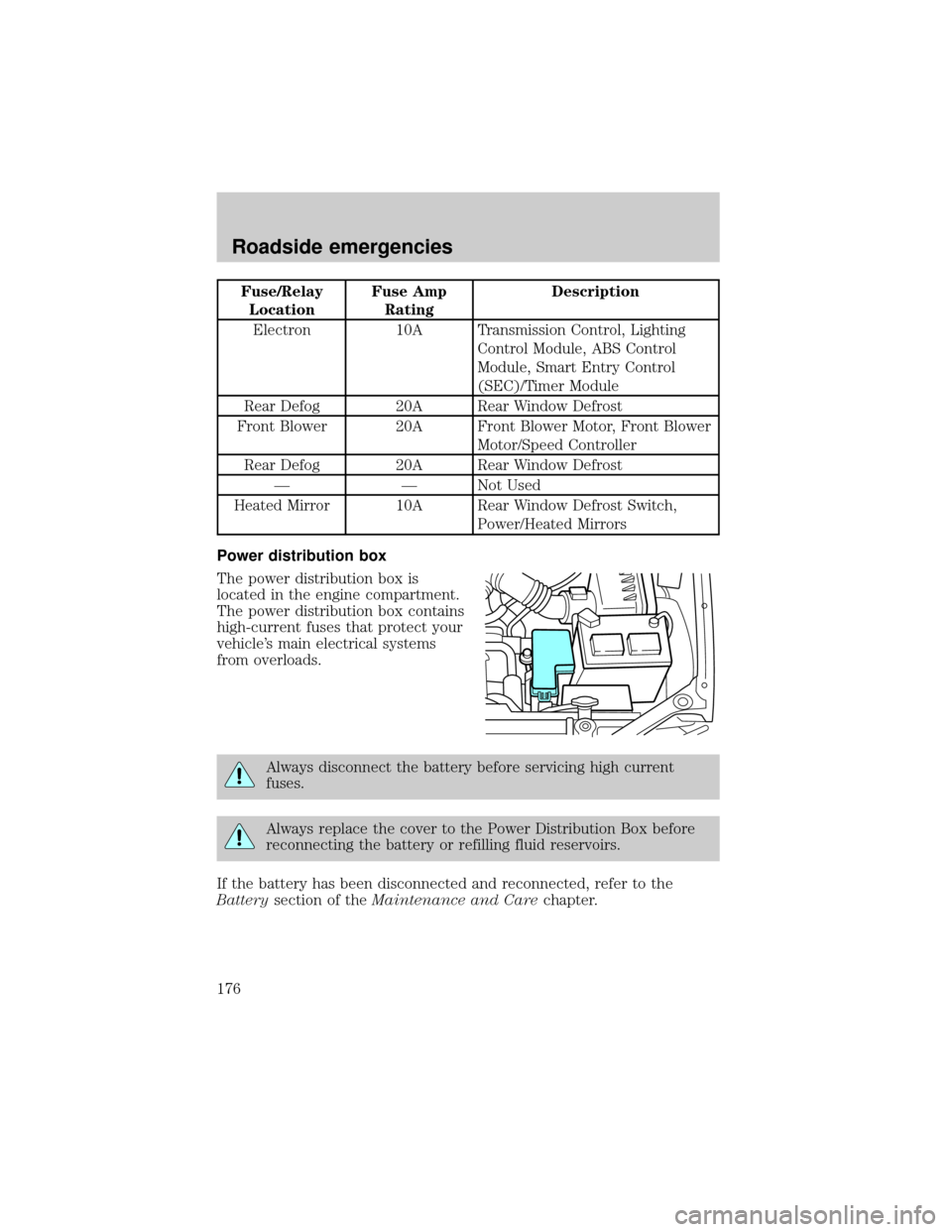
Power distribution box
The power distribution box is
located in the engine compartment.
The power distribution box contains
high-current fuses that protect your
vehicle's main electrical systems
from overloads.
Always disconnect the battery before servicing high current
fuses.
Always replace the cover to the Power Distribution Box before
reconnecting the battery or refilling fluid reservoirs.
If the battery has been disconnected and reconnected, refer to the
Batterysection of theMaintenance and Carechapter.
Roadside emergencies
176
Page 179 of 264
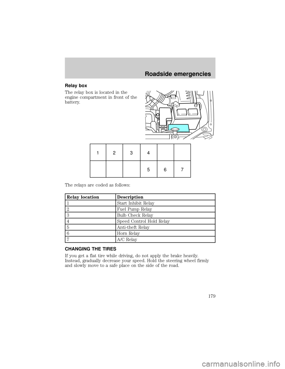
Relay box
The relay box is located in the
engine compartment in front of the
battery.
The relays are coded as follows:
Relay location Description
1 Start Inhibit Relay
2 Fuel Pump Relay
3 Bulb Check Relay
4 Speed Control Hold Relay
5 Anti-theft Relay
6 Horn Relay
7 A/C Relay
CHANGING THE TIRES
If you get a flat tire while driving, do not apply the brake heavily.
Instead, gradually decrease your speed. Hold the steering wheel firmly
and slowly move to a safe place on the side of the road.
1234
56 7
Roadside emergencies
179
Page 185 of 264
JUMP STARTING YOUR VEHICLE
The gases around the battery can explode if exposed to flames,
sparks, or lit cigarettes. An explosion could result in injury or
vehicle damage.
Do not push start your vehicle. You could damage the catalytic
converter.
Batteries contain sulfuric acid which can burn skin, eyes, and
clothing, if contacted.
Do not attempt to push start your vehicle. Automatic
transmissions do not have push-start capability.
Preparing your vehicle
1.Use only a 12±volt supply to start your vehicle.
2. Do not disconnect the battery of the disabled vehicle as this could
damage the vehicle's electrical system.
3. Park the booster vehicle close to the hood of the disabled vehicle
making sure the two vehiclesdo nottouch. Set the parking brake on
both vehicles and stay clear of the engine cooling fan and other moving
parts.
4. Check all battery terminals and remove any excessive corrosion before
you attach the battery cables. Ensure that vent caps are tight and level.
5. Turn the heater fan on in both vehicles to protect any electrical
surges. Turn all other accessories off.
Roadside emergencies
185