battery Mercury Villager 1999 s User Guide
[x] Cancel search | Manufacturer: MERCURY, Model Year: 1999, Model line: Villager, Model: Mercury Villager 1999Pages: 264, PDF Size: 2.19 MB
Page 186 of 264
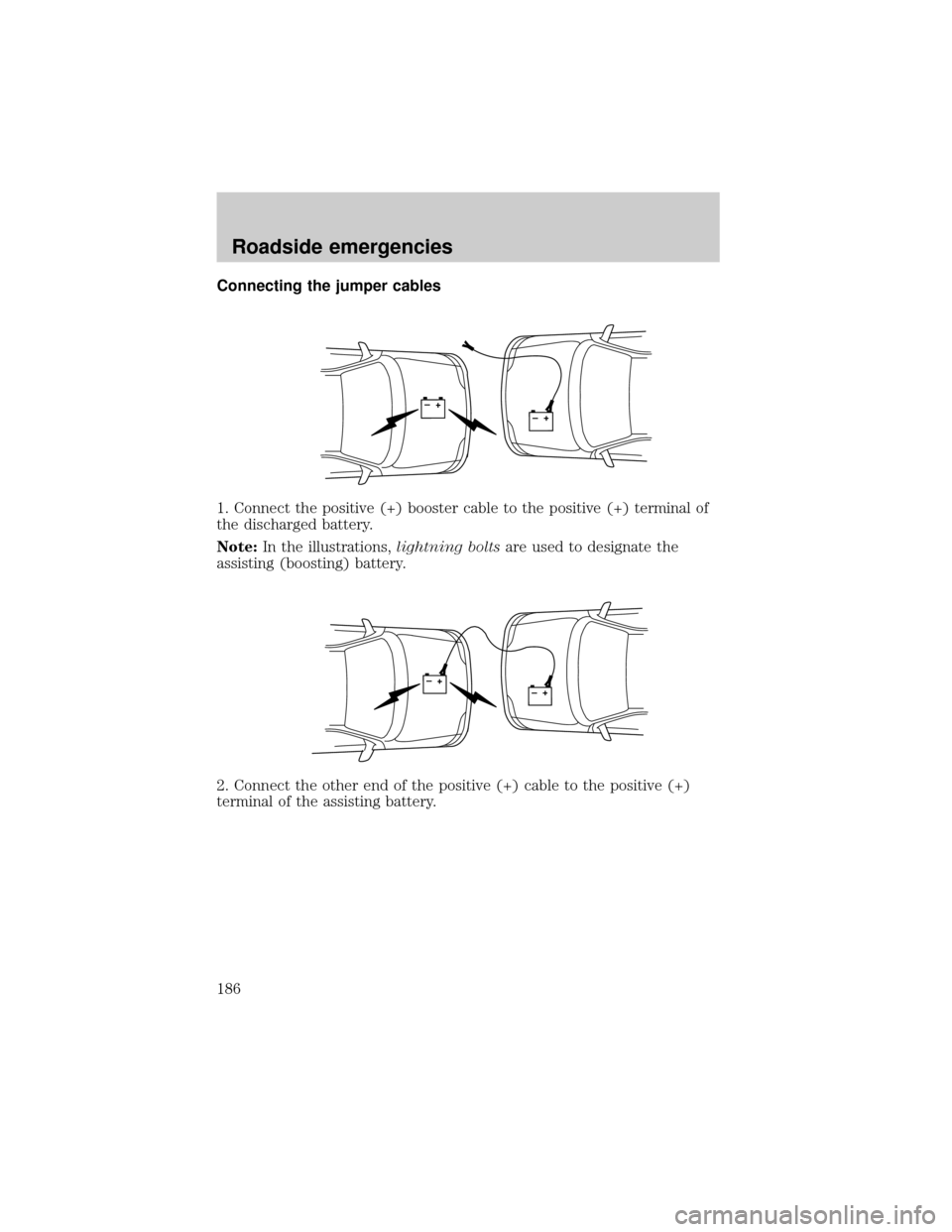
Connecting the jumper cables
1. Connect the positive (+) booster cable to the positive (+) terminal of
the discharged battery.
Note:In the illustrations,lightning boltsare used to designate the
assisting (boosting) battery.
2. Connect the other end of the positive (+) cable to the positive (+)
terminal of the assisting battery.
+–+–
+–+–
Roadside emergencies
186
Page 187 of 264
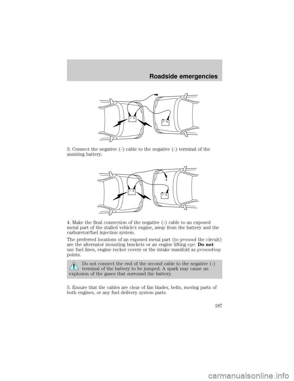
3. Connect the negative (-) cable to the negative (-) terminal of the
assisting battery.
4. Make the final connection of the negative (-) cable to an exposed
metal part of the stalled vehicle's engine, away from the battery and the
carburetor/fuel injection system.
The preferred locations of an exposed metal part (togroundthe circuit)
are the alternator mounting brackets or an engine liftingeye.Do not
use fuel lines, engine rocker covers or the intake manifold asgrounding
points.
Do not connect the end of the second cable to the negative (-)
terminal of the battery to be jumped. A spark may cause an
explosion of the gases that surround the battery.
5. Ensure that the cables are clear of fan blades, belts, moving parts of
both engines, or any fuel delivery system parts.
+–+–
+–+–
Roadside emergencies
187
Page 188 of 264
Jump starting
1. Start the engine of the booster vehicle and run the engine at
moderately increased speed.
2. Start the engine of the disabled vehicle.
3. Once the disabled vehicle has been started, run both engines for an
additional three minutes before disconnecting the jumper cables.
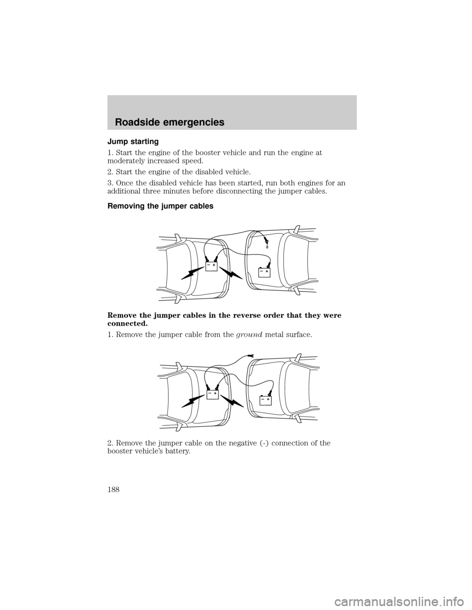
Removing the jumper cables
Remove the jumper cables in the reverse order that they were
connected.
1. Remove the jumper cable from thegroundmetal surface.
2. Remove the jumper cable on the negative (-) connection of the
booster vehicle's battery.
+–+–
+–+–
Roadside emergencies
188
Page 189 of 264
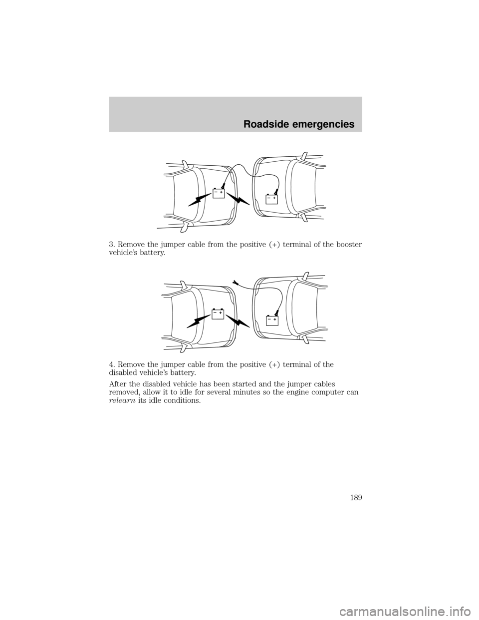
3. Remove the jumper cable from the positive (+) terminal of the booster
vehicle's battery.
4. Remove the jumper cable from the positive (+) terminal of the
disabled vehicle's battery.
After the disabled vehicle has been started and the jumper cables
removed, allow it to idle for several minutes so the engine computer can
relearnits idle conditions.
+–+–
+–+–
Roadside emergencies
189
Page 191 of 264
SERVICE RECOMMENDATIONS
To help you service your vehicle:
²We highlight do-it-yourself items in the engine compartment for easy
location.
²We provide a Scheduled Maintenance Guide which makes tracking
routine service easy.
If your vehicle requires professional service, your dealership can provide
necessary parts and service. Check your ªWarranty Guideº to find out
which parts and services are covered.
Use only recommended fuels, lubricants, fluids and service parts
conforming to specifications. Motorcraft parts are designed and built to
provide the best performance in your vehicle.
PRECAUTIONS WHEN SERVICING YOUR VEHICLE
Be especially careful when inspecting or servicing your vehicle.
²Do not work on a hot engine.
²When the engine is running, make sure that loose clothing, jewelry or
long hair does not get caught up in moving parts.
²Do not work on a vehicle with the engine running in an enclosed
space, unless you are sure you have enough ventilation.
²Keep all lit cigarettes, open flames and other lit material away from
the battery and all fuel related parts.
If you disconnect the battery, the engine must ªrelearnº its idle
conditions before your vehicle will drive properly, as explained inBattery
in this chapter.
Working with the engine off
1. Set the parking brake and ensure the gearshift is securely latched in P
(Park).
2. Turn off the engine and remove the key.
3. Block the wheels to prevent the vehicle from moving unexpectedly.
Working with the engine on
1. Set the parking brake and ensure the gearshift is securely latched in P
(Park).
2. Block the wheels to prevent the vehicle from moving unexpectedly.
Maintenance and care
191
Page 193 of 264
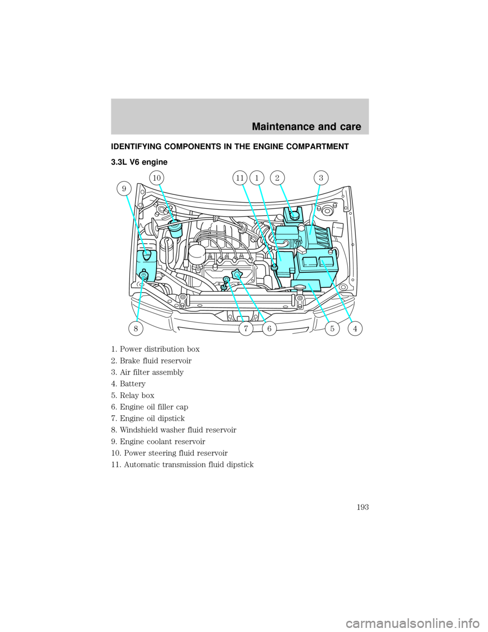
IDENTIFYING COMPONENTS IN THE ENGINE COMPARTMENT
3.3L V6 engine
1. Power distribution box
2. Brake fluid reservoir
3. Air filter assembly
4. Battery
5. Relay box
6. Engine oil filler cap
7. Engine oil dipstick
8. Windshield washer fluid reservoir
9. Engine coolant reservoir
10. Power steering fluid reservoir
11. Automatic transmission fluid dipstick
9
45678
1011123
Maintenance and care
193
Page 205 of 264
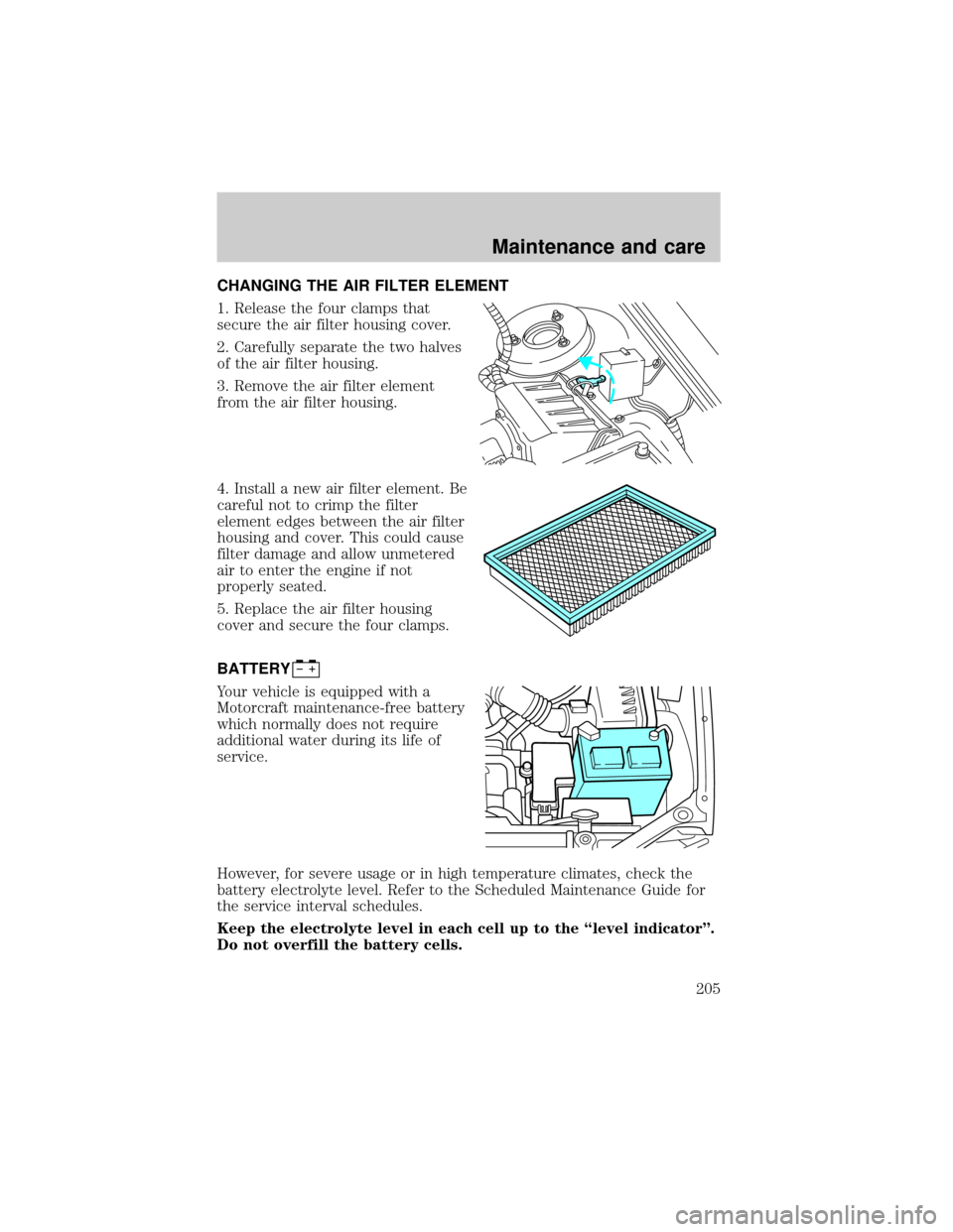
CHANGING THE AIR FILTER ELEMENT
1. Release the four clamps that
secure the air filter housing cover.
2. Carefully separate the two halves
of the air filter housing.
3. Remove the air filter element
from the air filter housing.
4. Install a new air filter element. Be
careful not to crimp the filter
element edges between the air filter
housing and cover. This could cause
filter damage and allow unmetered
air to enter the engine if not
properly seated.
5. Replace the air filter housing
cover and secure the four clamps.
BATTERY
Your vehicle is equipped with a
Motorcraft maintenance-free battery
which normally does not require
additional water during its life of
service.
However, for severe usage or in high temperature climates, check the
battery electrolyte level. Refer to the Scheduled Maintenance Guide for
the service interval schedules.
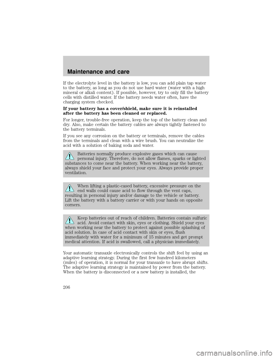
Keep the electrolyte level in each cell up to the ªlevel indicatorº.
Do not overfill the battery cells.
Maintenance and care
205
Page 206 of 264
If the electrolyte level in the battery is low, you can add plain tap water
to the battery, as long as you do not use hard water (water with a high
mineral or alkali content). If possible, however, try to only fill the battery
cells with distilled water. If the battery needs water often, have the
charging system checked.
If your battery has a cover/shield, make sure it is reinstalled
after the battery has been cleaned or replaced.
For longer, trouble-free operation, keep the top of the battery clean and
dry. Also, make certain the battery cables are always tightly fastened to
the battery terminals.
If you see any corrosion on the battery or terminals, remove the cables
from the terminals and clean with a wire brush. You can neutralize the
acid with a solution of baking soda and water.
Batteries normally produce explosive gases which can cause
personal injury. Therefore, do not allow flames, sparks or lighted
substances to come near the battery. When working near the battery,
always shield your face and protect your eyes. Always provide proper
ventilation.
When lifting a plastic-cased battery, excessive pressure on the
end walls could cause acid to flow through the vent caps,
resulting in personal injury and/or damage to the vehicle or battery.
Lift the battery with a battery carrier or with your hands on opposite
corners.
Keep batteries out of reach of children. Batteries contain sulfuric
acid. Avoid contact with skin, eyes or clothing. Shield your eyes
when working near the battery to protect against possible splashing of
acid solution. In case of acid contact with skin or eyes, flush
immediately with water for a minimum of 15 minutes and get prompt
medical attention. If acid is swallowed, call a physician immediately.
Your automatic transaxle electronically controls the shift feel by using an
adaptive learning strategy. During the first few hundred kilometers
(miles) of operation, it is normal for your transaxle to have abrupt shifts.
The adaptive learning strategy is maintained by power from the battery.
When the battery is disconnected or a new battery is installed, the
Maintenance and care
206
Page 207 of 264
transaxle must relearn its adaptive strategy. Optimal shifting will resume
within a few hundred kilometers (miles) of operation.
If the battery has been disconnected or a new battery has been installed,
the clock and the preset radio stations must be reset once the battery is
reconnected.
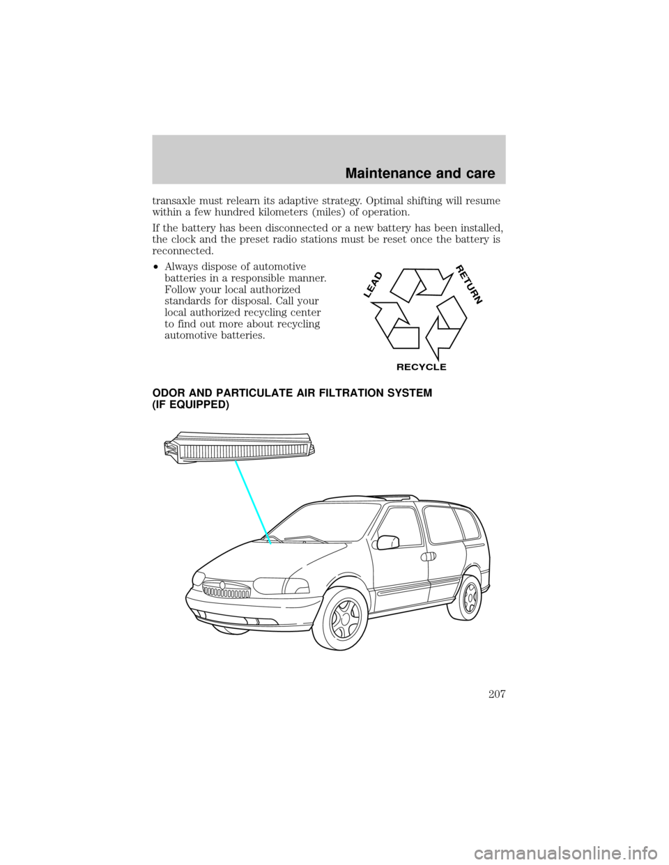
²Always dispose of automotive
batteries in a responsible manner.
Follow your local authorized
standards for disposal. Call your
local authorized recycling center
to find out more about recycling
automotive batteries.
ODOR AND PARTICULATE AIR FILTRATION SYSTEM
(IF EQUIPPED)
LEAD
RETURN
RECYCLE
Maintenance and care
207
Page 224 of 264
The scheduled maintenance items listed in the Scheduled Maintenance
Guide are essential to the life and performance of your vehicle and to its
emissions system.
If other than Ford, Motorcraft or Ford-authorized parts are used for
maintenance replacements or for service of components affecting
emission control, such non-Ford parts should be equivalent to genuine
Ford Motor Company parts in performance and durability.
Do not park, idle, or drive your vehicle in dry grass or other dry
ground cover. The emission system heats up the engine
compartment and exhaust system, which can start a fire.
Illumination of the ªService Engine Soonº light, charging system warning
light or the temperature warning light, fluid leaks, strange odors, smoke
or loss of engine power, could indicate that the emission control system
is not working properly.
Exhaust leaks may result in entry of harmful and potentially
lethal fumes into the passenger compartment.
Do not make any unauthorized changes to your vehicle or engine. By
law, vehicle owners and anyone who manufactures, repairs, services,
sells, leases, trades vehicles, or supervises a fleet of vehicles are not
permitted to intentionally remove an emission control device or prevent
it from working. Information about your vehicle's emission system is on
the Vehicle Emission Control Information Decal located on or near the
engine. This decal identifies engine displacement and gives some tune up
specifications.
Please consult your ªWarranty Guideº for complete emission warranty
information.
Readiness for Inspection/Maintenance (I/M) testing
In some localities, it may be a legal requirement to pass an I/M test of
the on-board diagnostics system. If your ªCheck Engine/Service Engine
Soonº light is on, refer to the description in theWarning Lights and
Chimessection of theInstrumentationchapter. Your vehicle may not
pass the I/M test with the ªCheck Engine/Service Engine Soonº light on.
If the vehicle's powertrain system or its battery has just been serviced,
the on-board diagnostics system is reset to a ªnot ready for I/M testº
Maintenance and care
224