radio Mercury Villager 2000 s Owner's Guide
[x] Cancel search | Manufacturer: MERCURY, Model Year: 2000, Model line: Villager, Model: Mercury Villager 2000Pages: 256, PDF Size: 2.21 MB
Page 82 of 256
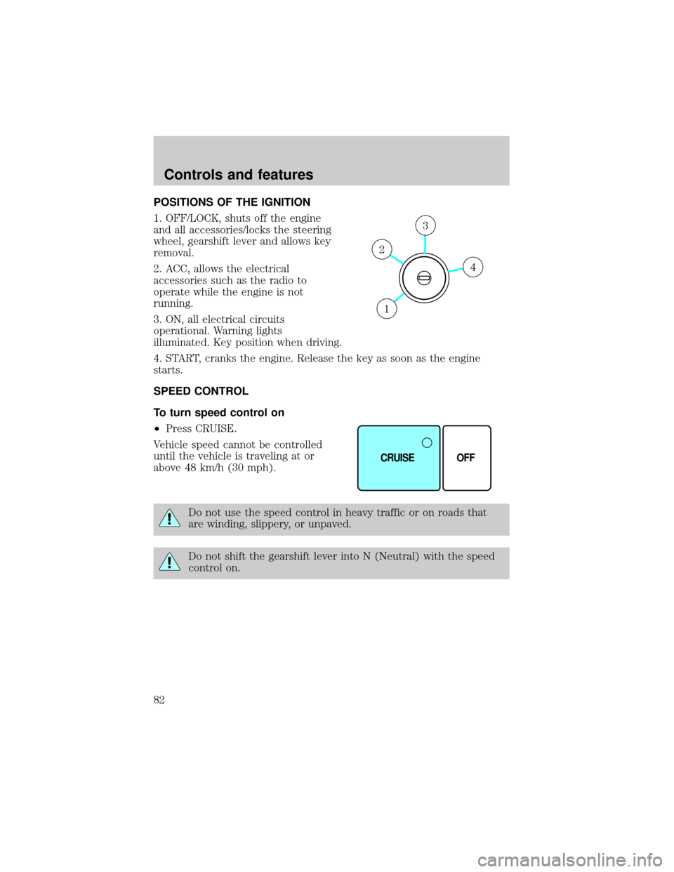
POSITIONS OF THE IGNITION
1. OFF/LOCK, shuts off the engine
and all accessories/locks the steering
wheel, gearshift lever and allows key
removal.
2. ACC, allows the electrical
accessories such as the radio to
operate while the engine is not
running.
3. ON, all electrical circuits
operational. Warning lights
illuminated. Key position when driving.
4. START, cranks the engine. Release the key as soon as the engine
starts.
SPEED CONTROL
To turn speed control on
²Press CRUISE.
Vehicle speed cannot be controlled
until the vehicle is traveling at or
above 48 km/h (30 mph).
Do not use the speed control in heavy traffic or on roads that
are winding, slippery, or unpaved.
Do not shift the gearshift lever into N (Neutral) with the speed
control on.
4
3
2
1
CRUISE OFF
Controls and features
82
Page 86 of 256
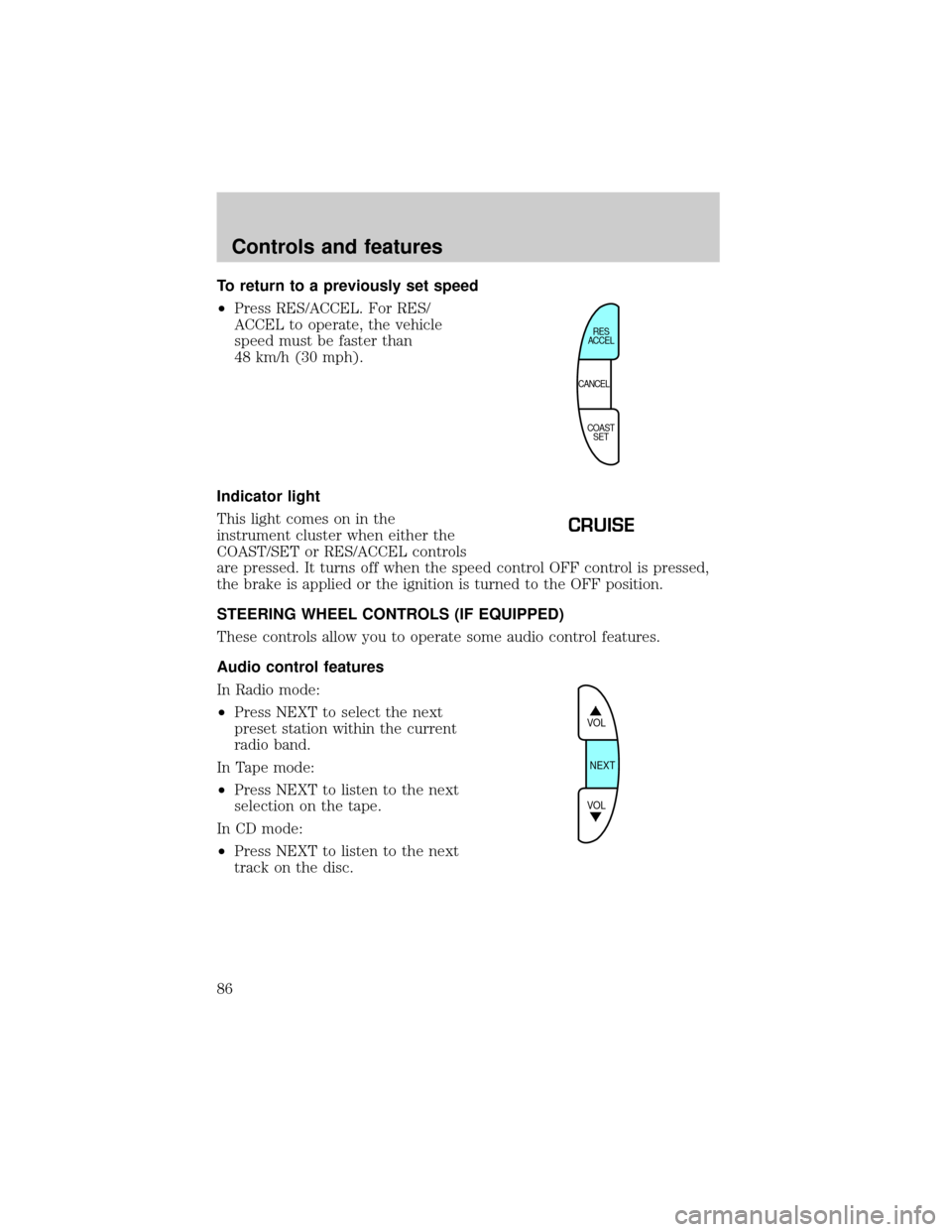
To return to a previously set speed
²Press RES/ACCEL. For RES/
ACCEL to operate, the vehicle
speed must be faster than
48 km/h (30 mph).
Indicator light
This light comes on in the
instrument cluster when either the
COAST/SET or RES/ACCEL controls
are pressed. It turns off when the speed control OFF control is pressed,
the brake is applied or the ignition is turned to the OFF position.
STEERING WHEEL CONTROLS (IF EQUIPPED)
These controls allow you to operate some audio control features.
Audio control features
In Radio mode:
²Press NEXT to select the next
preset station within the current
radio band.
In Tape mode:
²Press NEXT to listen to the next
selection on the tape.
In CD mode:
²Press NEXT to listen to the next
track on the disc.
CANCELRES
ACCEL
COAST
SET
CRUISE
VOL
NEXT
VOL
Controls and features
86
Page 94 of 256
with a single built-in device. This feature will learn the radio frequency
codes of most current transmitters to operate garage doors, entry gates,
security systems, entry door locks, and home or office lighting.
When programming your HomeLinktUniversal Transceiver, to a
garage door or gate be sure that people and objects are out of
the way to prevent potential harm or damage.
Do not use the HomeLinktUniversal Transceiver with any garage door
opener that lacks safety stop and reverse features as required by U.S.
federal safety standards (this includes any garage door opener model
manufactured before April 1, 1982). A garage door which cannot detect
an object, signaling the door to stop and reverse, does not meet current
U.S. federal safety standards. For more information on this matter, call
toll-free: 1±800±355±3515 or on the Internet atHomeLink.jci.com.
Programming
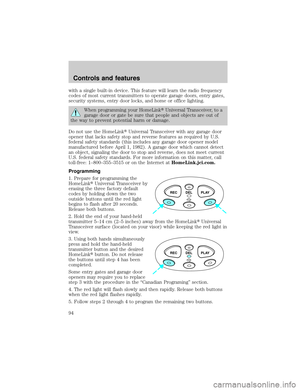
1. Prepare for programming the
HomeLinktUniversal Transceiver by
erasing the three factory default
codes by holding down the two
outside buttons until the red light
begins to flash after 20 seconds.
Release both buttons.
2. Hold the end of your hand-held
transmitter 5±14 cm (2±5 inches) away from the HomeLinktUniversal
Transceiver surface (located on your visor) while keeping the red light in
view.
3. Using both hands simultaneously
press and hold the hand-held
transmitter button and the desired
HomeLinktbutton. Do not release
the buttons until step 4 has been
completed.
Some entry gates and garage door
openers may require you to replace
step 3 with the procedure in the ªCanadian Programingº section.
4. The red light will flash slowly and then rapidly. Release both buttons
when the red light flashes rapidly.
5. Follow steps 2 through 4 to program the remaining two buttons.
REC DEL PLAY
REC DEL PLAY
Controls and features
94
Page 104 of 256
The system automatically turns off after 15 seconds or when the ignition
is turned to the RUN position.
The inside lights will not turn off if:
²they have been turned on with the headlamp control or
²any door is open.
The battery saver will shut off the interior lamps after 30 minutes if the
front door is left open or after 60 minutes if the liftgate is left open.
Replacing the battery
The transmitter is powered by one coin type three-volt lithium battery.
Typical operating range will allow you to be up to 10 meters (33 feet)
away from your vehicle. A decrease in operating range can be caused by:
²weather conditions
²nearby radio towers
²structures around the vehicle
²other vehicles parked next to the vehicle
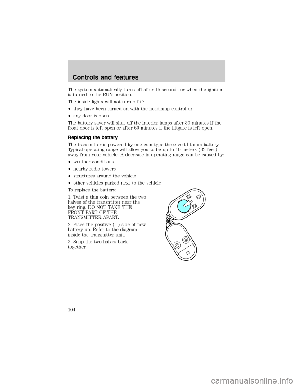
To replace the battery:
1. Twist a thin coin between the two
halves of the transmitter near the
key ring. DO NOT TAKE THE
FRONT PART OF THE
TRANSMITTER APART.
2. Place the positive (+) side of new
battery up. Refer to the diagram
inside the transmitter unit.
3. Snap the two halves back
together.
Controls and features
104
Page 147 of 256

PREPARING TO START YOUR VEHICLE
Engine starting is controlled by the powertrain control system. This
system meets all Canadian Interference-Causing Equipment standard
requirements regulating the impulse electrical field strength of radio
noise.
When starting a fuel-injected engine, avoid pressing the accelerator
before or during starting. Only use the accelerator when you have
difficulty starting the engine. For more information on starting the
vehicle, refer toStarting the enginein this chapter.
Extended idling at high engine speeds can produce very high
temperatures in the engine and exhaust system, creating the risk
of fire or other damage.
Do not park, idle, or drive your vehicle in dry grass or other dry
ground cover. The emission system heats up the engine
compartment and exhaust system, which can start a fire.
Do not start your vehicle in a closed garage or in other enclosed
areas. Exhaust fumes can be toxic. Always open the garage door
before you start the engine. SeeGuarding against exhaust fumesin
this chapter for more instructions.
If you smell exhaust fumes inside your vehicle, have your dealer
inspect your vehicle immediately. Do not drive if you smell
exhaust fumes.
Starting
147
Page 170 of 256
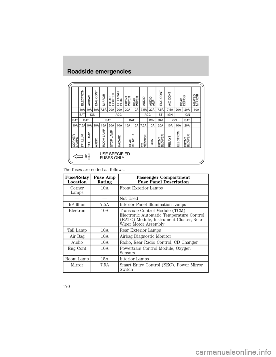
The fuses are coded as follows.
Fuse/Relay
LocationFuse Amp
RatingPassenger Compartment
Fuse Panel Description
Corner
Lamps10A Front Exterior Lamps
Ð Ð Not Used
I/P Illum 7.5A Interior Panel Illumination Lamps
Electron 10A Transaxle Control Module (TCM),
Electronic Automatic Temperature Control
(EATC) Module, Instrument Cluster, Rear
Wiper Motor Assembly
Tail Lamp 10A Rear Exterior Lamps
Air Bag 10A Airbag Diagnostic Monitor
Audio 10A Radio, Rear Radio Control, CD Changer
Eng Cont 10A Powertrain Control Module, Oxygen
Sensors
Room Lamp 15A Interior Lamps
Mirror 7.5A Smart Entry Control (SEC), Power Mirror
Switch
CORNER
LAMPS
I/P ILLUM
10A BAT
7.5ABAT IGN ACC
USE SPECIFIED
FUSES ONLY
ACC 10A
10A 10A
10A 10A
15A 7.5A
20A 20A
10A 20A
15A 20A
15A 7.5A 10A 7.5A
BAT BAT BAT
10A 20A
IGNST
20A 7.5A
BAT
20A 20A 10A
BAT IGN IGN
10A 7.5A
10A 20A
IGN
UP
SIDEELECTRON
TAIL LAMP AIRBAG
AUDIO ENG CONT
ROOM LAMP MIRROR
RELAYS A/C CONT
ELECTRON
FRONT
BLOWERREAR
DEFOG
HEATED
MIRROR STOP LAMPCIGAR
LIGHTER
HAZARDRR POWER
PLUG
TURNAUDIO
AMP
FRONT
BLOWERENG CONT REAR
BLOWER
O2
SENSORFRONT
WIPER
REAR
WIPER
AUDIO
Roadside emergencies
170
Page 171 of 256
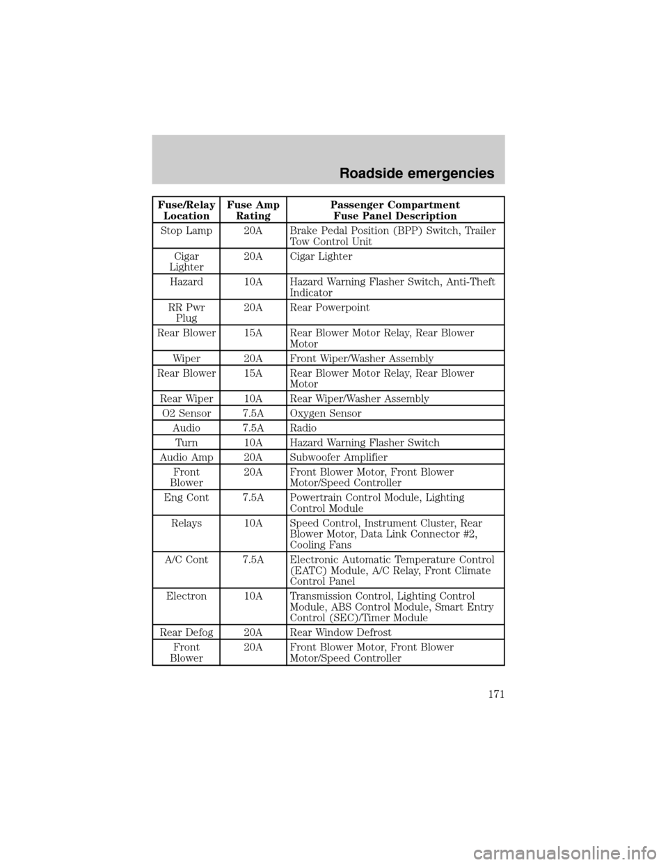
Fuse/Relay
LocationFuse Amp
RatingPassenger Compartment
Fuse Panel Description
Stop Lamp 20A Brake Pedal Position (BPP) Switch, Trailer
Tow Control Unit
Cigar
Lighter20A Cigar Lighter
Hazard 10A Hazard Warning Flasher Switch, Anti-Theft
Indicator
RR Pwr
Plug20A Rear Powerpoint
Rear Blower 15A Rear Blower Motor Relay, Rear Blower
Motor
Wiper 20A Front Wiper/Washer Assembly
Rear Blower 15A Rear Blower Motor Relay, Rear Blower
Motor
Rear Wiper 10A Rear Wiper/Washer Assembly
O2 Sensor 7.5A Oxygen Sensor
Audio 7.5A Radio
Turn 10A Hazard Warning Flasher Switch
Audio Amp 20A Subwoofer Amplifier
Front
Blower20A Front Blower Motor, Front Blower
Motor/Speed Controller
Eng Cont 7.5A Powertrain Control Module, Lighting
Control Module
Relays 10A Speed Control, Instrument Cluster, Rear
Blower Motor, Data Link Connector #2,
Cooling Fans
A/C Cont 7.5A Electronic Automatic Temperature Control
(EATC) Module, A/C Relay, Front Climate
Control Panel
Electron 10A Transmission Control, Lighting Control
Module, ABS Control Module, Smart Entry
Control (SEC)/Timer Module
Rear Defog 20A Rear Window Defrost
Front
Blower20A Front Blower Motor, Front Blower
Motor/Speed Controller
Roadside emergencies
171
Page 203 of 256
Battery posts, terminals and related accessories contain lead and
lead compunds. Wash hands after handling.
Your automatic transaxle electronically controls the shift feel by using an
adaptive learning strategy. During the first few hundred kilometers
(miles) of operation, it is normal for your transaxle to have abrupt shifts.
The adaptive learning strategy is maintained by power from the battery.
When the battery is disconnected or a new battery is installed, the
transaxle must relearn its adaptive strategy. Optimal shifting will resume
within a few hundred kilometers (miles) of operation.
If the battery has been disconnected or a new battery has been installed,
the clock and the preset radio stations must be reset once the battery is
reconnected.
²Always dispose of automotive
batteries in a responsible manner.
Follow your local authorized
standards for disposal. Call your
local authorized recycling center
to find out more about recycling
automotive batteries.
LEAD
RETURN
RECYCLE
Maintenance and care
203
Page 235 of 256
Item Ford part
nameFord part
numberFord
specification
Disc brake
caliper railsSilicone Brake
Caliper Grease
and Dielectric
CompoundD7AZ-19A331-A
(Motorcraft
WA-10)ESE-M1C171-A
Constant
velocity jointsCV Joint Grease
(High Temp.)E43Z-19590-A ESP-M1C207-A
Windshield
washer fluidUltra-clear
Windshield
Washer
ConcentrateC9AZ-19550-AC ESR-M17P5-A
ENGINE DATA
Engine 3.3L V6 engine
Cubic inches 200
Required fuel 87 octane
Firing order 1-2-3-4-5-6
Spark plug gap 1.0-1.1 mm (0.039-0.043 inch)
Ignition system
1Distributor ignition system
Compression ratio 8.9:1
1This ignition system meets all Canadian Interference-Causing
Equipment standard requirements regulating the impulse electrical field
strength of radio noise.
VEHICLE DIMENSIONS
Vehicle dimensions mm (in)
(1) Overall length 4 945.4 (194.7)
(2) Overall width 1 902.5 (74.9)
(3) Overall height (with luggage
rack)1 780.5 (70.1)
(4) Wheelbase 2 849.9 (112.2)
(5) Track - Front 1 610.4 (63.4)
(5) Track - Rear 1 610.4 (63.4)
Capacities and specifications
235
Page 248 of 256

Hood deflectors
Lubricants and oils
Molded splash guards
Molded vinyl floor mats
Rear air deflectors
Side window air deflectors
Touch-up paint
Universal floor mats
For maximum vehicle performance, keep the following information in
mind when adding accessories or equipment to your vehicle:
²When adding accessories, equipment, passengers and luggage to your
vehicle, do not exceed the total weight capacity of the vehicle or of
the front or rear axle (GVWR or GAWR as indicated on the Safety
compliance certification label). Consult your dealer for specific weight
information.
²The Federal Communications Commission (FCC) and Canadian Radio
Telecommunications Commission (CRTC) regulate the use of mobile
communications systems - such as two-way radios, telephones and
theft alarms - that are equipped with radio transmitters. Any such
equipment installed in your vehicle should comply with FCC or CRTC
regulations and should be installed only by a qualified service
technician.
²Mobile communications systems may harm the operation of your
vehicle, particularly if they are not properly designed for automotive
use or are not properly installed. When operated, such systems may
cause the engine to stumble or stall. In addition, such systems may be
damaged or their performance may be affected by operating your
vehicle. (Citizens band [CB] transceivers, garage door openers and
other transmitters with outputs of five watts or less will not ordinarily
affect your vehicle's operation.)
²Ford cannot assume responsibility for any adverse effects or damage
that may result from the use of such equipment.
Customer assistance
248