transmission Mercury Villager 2000 Owner's Manuals
[x] Cancel search | Manufacturer: MERCURY, Model Year: 2000, Model line: Villager, Model: Mercury Villager 2000Pages: 256, PDF Size: 2.21 MB
Page 12 of 256
Light is blinking:
Engine misfire is occurring which could damage your catalytic converter.
You should drive in a moderate fashion (avoid heavy acceleration and
deceleration) and have your vehicle serviced at the first available
opportunity.
Under engine misfire conditions, excessive exhaust temperatures
could damage the catalytic converter, the fuel system, interior
floor coverings or other vehicle components, possibly causing a fire.
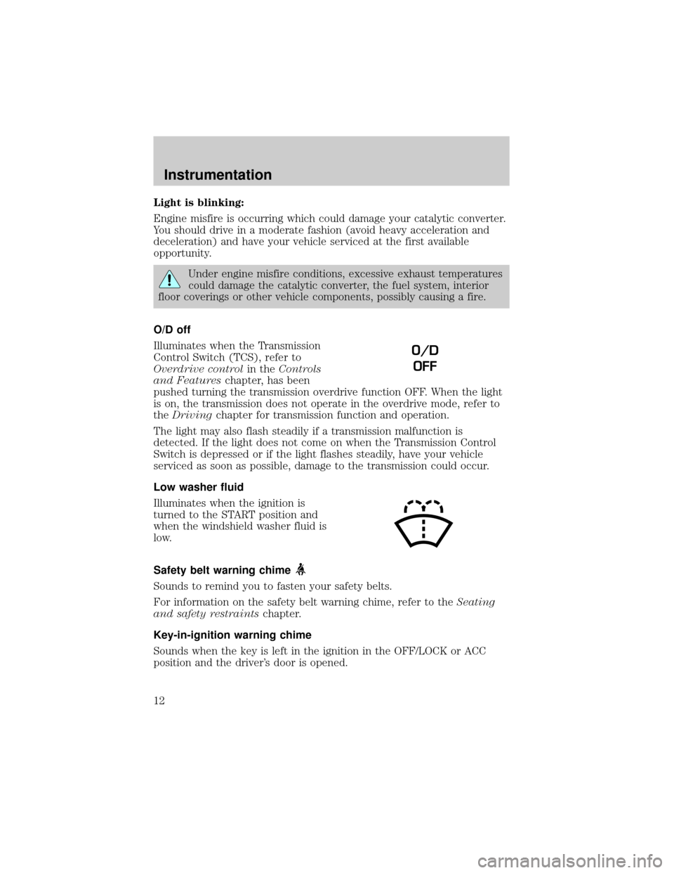
O/D off
Illuminates when the Transmission
Control Switch (TCS), refer to
Overdrive controlin theControls
and Featureschapter, has been
pushed turning the transmission overdrive function OFF. When the light
is on, the transmission does not operate in the overdrive mode, refer to
theDrivingchapter for transmission function and operation.
The light may also flash steadily if a transmission malfunction is
detected. If the light does not come on when the Transmission Control
Switch is depressed or if the light flashes steadily, have your vehicle
serviced as soon as possible, damage to the transmission could occur.
Low washer fluid
Illuminates when the ignition is
turned to the START position and
when the windshield washer fluid is
low.
Safety belt warning chime
Sounds to remind you to fasten your safety belts.
For information on the safety belt warning chime, refer to theSeating
and safety restraintschapter.
Key-in-ignition warning chime
Sounds when the key is left in the ignition in the OFF/LOCK or ACC
position and the driver's door is opened.
O/D
OFF
Instrumentation
12
Page 89 of 256
OVERDRIVE CONTROL
Activating overdrive
D (Overdrive) is the normal drive position for the best fuel economy.
The overdrive function allows automatic upshifts from third to fourth
gear.
Deactivating overdrive
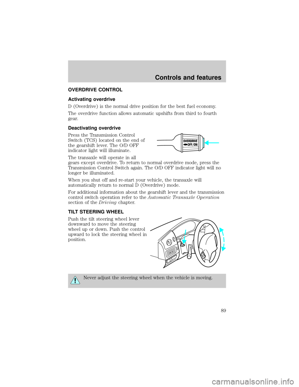
Press the Transmission Control
Switch (TCS) located on the end of
the gearshift lever. The O/D OFF
indicator light will illuminate.
The transaxle will operate in all
gears except overdrive. To return to normal overdrive mode, press the
Transmission Control Switch again. The O/D OFF indicator light will no
longer be illuminated.
When you shut off and re-start your vehicle, the transaxle will
automatically return to normal D (Overdrive) mode.
For additional information about the gearshift lever and the transmission
control switch operation refer to theAutomatic Transaxle Operation
section of theDrivingchapter.
TILT STEERING WHEEL
Push the tilt steering wheel lever
downward to move the steering
wheel up or down. Push the control
upward to lock the steering wheel in
position.
Never adjust the steering wheel when the vehicle is moving.
OVERDRIVE
OFF/ON
Controls and features
89
Page 155 of 256
²high crown in center of road
²high crosswinds
²wheels out of alignment
²loose or worn components in steering linkage
AUTOMATIC TRANSAXLE OPERATION
Brake-shift interlock
This vehicle is equipped with a brake-shift interlock feature that prevents
the gearshift lever from being moved from P (Park) when the ignition is
in the ON position unless brake pedal is depressed.
If you cannot move the gearshift lever out of P (Park) with ignition in
the ON position and the brake pedal depressed:
1. Apply the parking brake, turn ignition key to OFF/LOCK, then remove
the key.
2. Insert the key and turn it to ACC. Apply the brake pedal and shift to
N (Neutral).
3. Start the vehicle.
Do not drive your vehicle until you verify that the brakelamps
are working.
If your vehicle gets stuck in mud or snow it may be rocked out by
shifting from forward and reverse gears, stopping between shifts, in a
steady pattern. Press lightly on the accelerator in each gear.
Do not rock the vehicle if the engine is not at normal operating
temperature or damage to the transmission may occur.
Do not rock the vehicle for more than a few minutes or damage
to the transmission and tires may occur or the engine may
overheat.
Always set the parking brake fully and make sure the gearshift is
latched in P (Park). Turn off the ignition whenever you leave
your vehicle.
Driving
155
Page 160 of 256

Once through the water, always try the brakes. Wet brakes do not stop
the vehicle as effectively as dry brakes. Drying can be improved by
moving your vehicle slowly while applying light pressure on the brake
pedal.
Driving through deep water where the transaxle is submerged
may allow water into the transaxle and cause internal damage.
VEHICLE LOADING
Before loading a vehicle, familiarize yourself with the following terms:
²Base Curb Weight:Weight of the vehicle including any standard
equipment, fluids, lubricants, etc. It does not include passengers or
aftermarket equipment.
²Payload:Combined maximum allowable weight of cargo, passengers
and optional equipment. The payload equals the gross vehicle weight
rating minus base curb weight.
²GVW (Gross Vehicle Weight):Base curb weight plus payload
weight. The GVW is not a limit or a specification.
²GVWR (Gross Vehicle Weight Rating):Maximum total weight of
the base vehicle, passengers, optional equipment and cargo. The
GVWR is specific to each vehicle and is listed on the Safety
Certification Label on the driver's door pillar.
²GAWR (Gross Axle Weight Rating):Carrying capacity for each axle
system. The GAWR is specific to each vehicle and is listed on the
Safety Certification Label on the driver's door pillar.
²GCWR (Gross Combined Weight Rating):Maximum combined
weight of towing vehicle (including passengers and cargo) and the
trailer. The GCWR indicates the maximum loaded weight that the
vehicle is designed to tow.
²Maximum Trailer Weight Rating:Maximum weight of a trailer the
vehicle is permitted to tow. The maximum trailer weight rating is
determined by subtracting the vehicle curb weight for each
engine/transmission combination, any required option weight for trailer
towing and the weight of the driver from the GCWR for the towing
vehicle.
²Maximum Trailer Weight:maximum weight of a trailer the loaded
vehicle (including passengers and cargo) is permitted to tow. It is
determined by subtracting the weight of the loaded trailer towing
vehicle from the GCWR for the towing vehicle.
Driving
160
Page 162 of 256
TRAILER TOWING
The trailer towing table shows the maximum allowable maximum GCWR
and trailer weight.
Maximum GCWR - kg (lbs.)Trailer weight range
(0 - maximum) - kg (lbs.)
3 628 ( 8 000) 0-1 588 (0-3 500)
Do not exceed the GVWR or the GAWR specified on the
certification label.
Towing trailers beyond the maximum recommended gross trailer
weight could result in engine damage, transmission/axle damage,
structural damage, loss of control, and personal injury.
The optional Trailer Tow Prep Package is recommended for towing of
any trailer since it provides a heavy duty battery, conventional size spare
tire and wiring.
Trailer towing puts additional loads on your vehicle's engine,
transmission, axle, brakes, tires, and suspension. For your safety and to
maximize vehicle performance, be sure to use the proper equipment
while towing.
Follow these guidelines to ensure safe towing procedure:
²Stay within your vehicle's load limits. If exceeded, cargo should be
removed from the trailer and/or the vehicle until all weights are within
specified limits.
²Thoroughly prepare your vehicle for towing. Refer toPreparing to
towin this chapter.
²Use extra caution when driving while trailer towing. Refer toDriving
while you towin this chapter.
²Service your vehicle more frequently if you tow a trailer. Refer to the
severe duty schedule in the Scheduled Maintenance Guide.
²Do not tow a trailer until your vehicle has been driven at least 800 km
(500 miles).
²Refer to the instructions included with towing accessories for the
proper installation and adjustment specifications.
Driving
162
Page 171 of 256
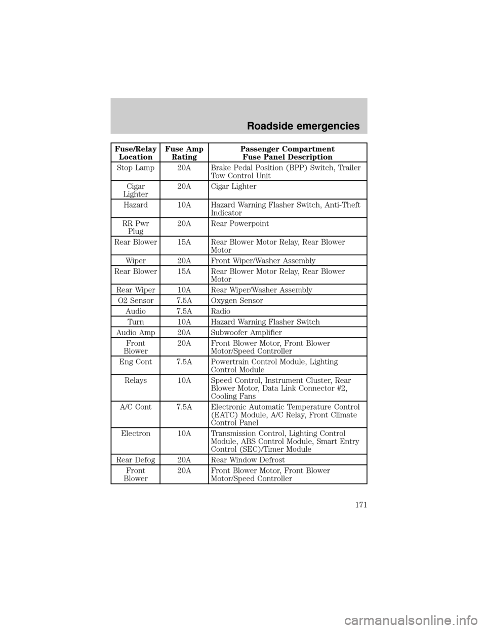
Fuse/Relay
LocationFuse Amp
RatingPassenger Compartment
Fuse Panel Description
Stop Lamp 20A Brake Pedal Position (BPP) Switch, Trailer
Tow Control Unit
Cigar
Lighter20A Cigar Lighter
Hazard 10A Hazard Warning Flasher Switch, Anti-Theft
Indicator
RR Pwr
Plug20A Rear Powerpoint
Rear Blower 15A Rear Blower Motor Relay, Rear Blower
Motor
Wiper 20A Front Wiper/Washer Assembly
Rear Blower 15A Rear Blower Motor Relay, Rear Blower
Motor
Rear Wiper 10A Rear Wiper/Washer Assembly
O2 Sensor 7.5A Oxygen Sensor
Audio 7.5A Radio
Turn 10A Hazard Warning Flasher Switch
Audio Amp 20A Subwoofer Amplifier
Front
Blower20A Front Blower Motor, Front Blower
Motor/Speed Controller
Eng Cont 7.5A Powertrain Control Module, Lighting
Control Module
Relays 10A Speed Control, Instrument Cluster, Rear
Blower Motor, Data Link Connector #2,
Cooling Fans
A/C Cont 7.5A Electronic Automatic Temperature Control
(EATC) Module, A/C Relay, Front Climate
Control Panel
Electron 10A Transmission Control, Lighting Control
Module, ABS Control Module, Smart Entry
Control (SEC)/Timer Module
Rear Defog 20A Rear Window Defrost
Front
Blower20A Front Blower Motor, Front Blower
Motor/Speed Controller
Roadside emergencies
171
Page 181 of 256
Do not push start your vehicle. You could damage the catalytic
converter.
Batteries contain sulfuric acid which can burn skin, eyes, and
clothing, if contacted.
Do not attempt to push start your vehicle. Automatic
transmissions do not have push-start capability.
Preparing your vehicle
1.Use only a 12±volt supply to start your vehicle.
2. Do not disconnect the battery of the disabled vehicle as this could
damage the vehicle's electrical system.
3. Park the booster vehicle close to the hood of the disabled vehicle
making sure the two vehiclesdo nottouch. Set the parking brake on
both vehicles and stay clear of the engine cooling fan and other moving
parts.
4. Check all battery terminals and remove any excessive corrosion before
you attach the battery cables. Ensure that vent caps are tight and level.
5. Turn the heater fan on in both vehicles to protect any electrical
surges. Turn all other accessories off.
Connecting the jumper cables
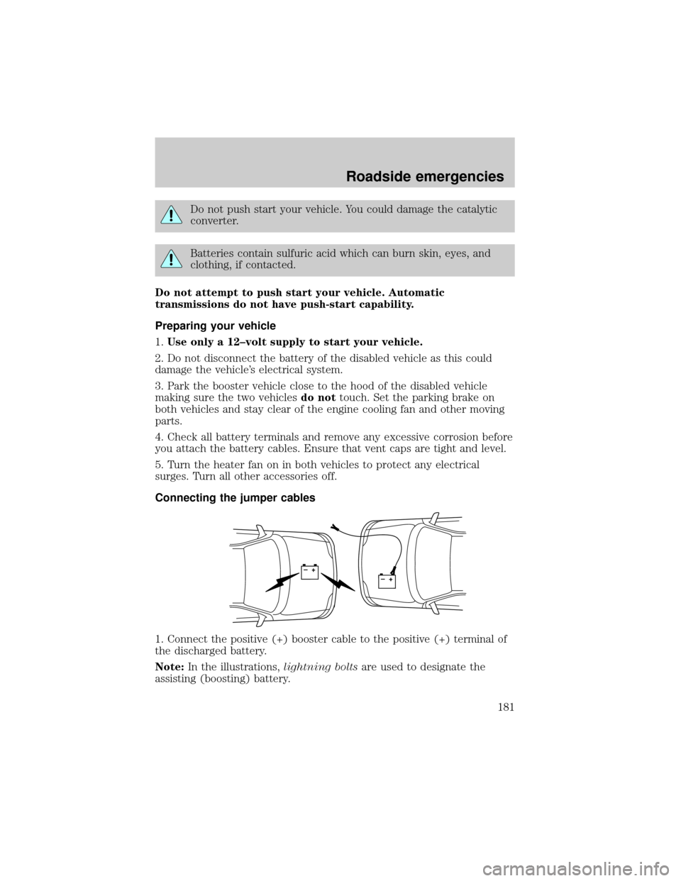
1. Connect the positive (+) booster cable to the positive (+) terminal of
the discharged battery.
Note:In the illustrations,lightning boltsare used to designate the
assisting (boosting) battery.
+–+–
Roadside emergencies
181
Page 185 of 256
WRECKER TOWING
If you need to have your vehicle towed, contact a professional towing
service or, if you are a member, your roadside assistance center.
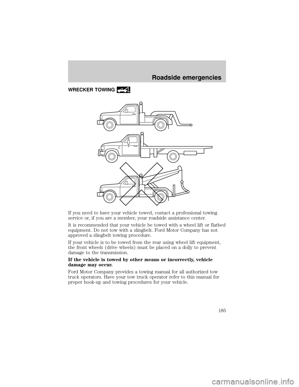
It is recommended that your vehicle be towed with a wheel lift or flatbed
equipment. Do not tow with a slingbelt. Ford Motor Company has not
approved a slingbelt towing procedure.
If your vehicle is to be towed from the rear using wheel lift equipment,
the front wheels (drive wheels) must be placed on a dolly to prevent
damage to the transmission.
If the vehicle is towed by other means or incorrectly, vehicle
damage may occur.
Ford Motor Company provides a towing manual for all authorized tow
truck operators. Have your tow truck operator refer to this manual for
proper hook-up and towing procedures for your vehicle.
Roadside emergencies
185
Page 188 of 256
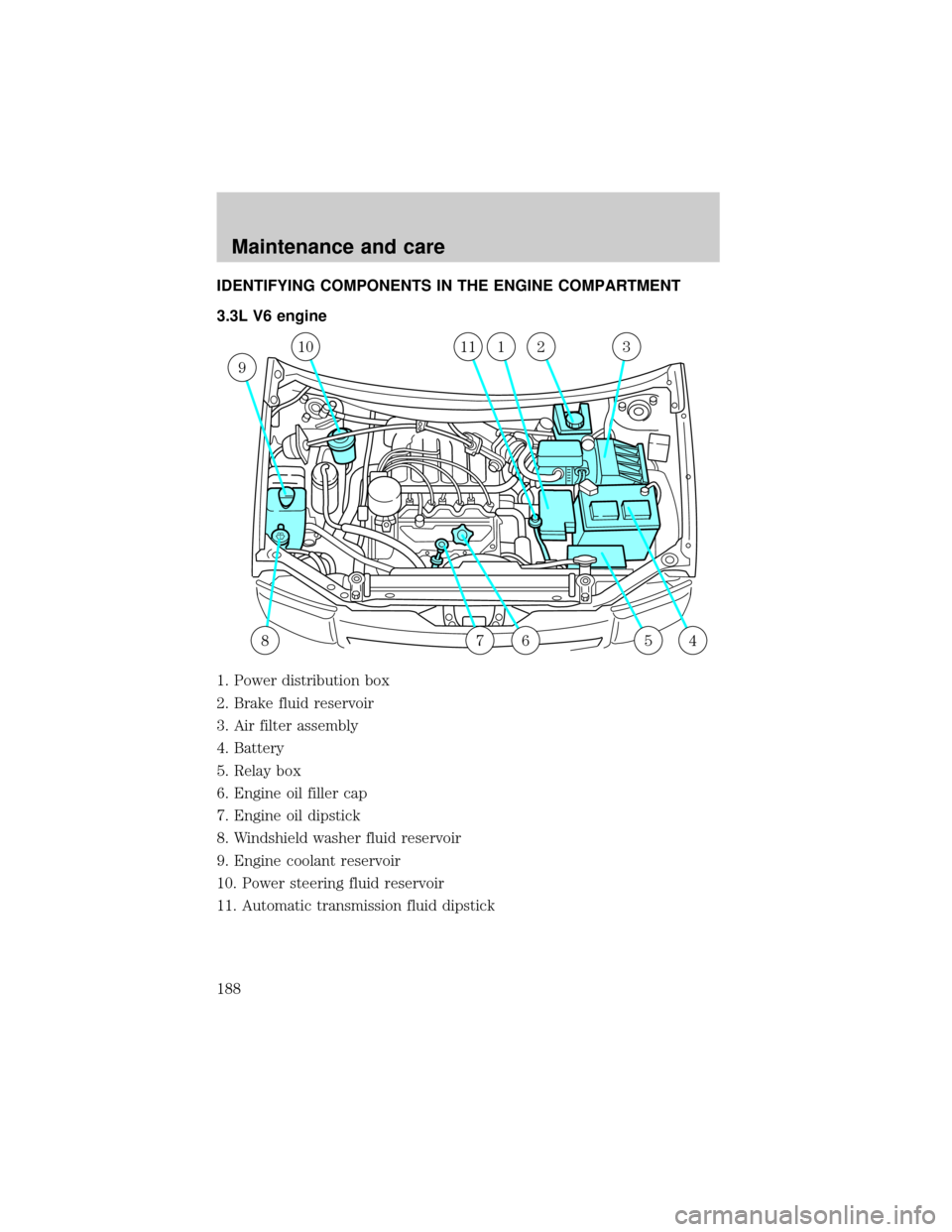
IDENTIFYING COMPONENTS IN THE ENGINE COMPARTMENT
3.3L V6 engine
1. Power distribution box
2. Brake fluid reservoir
3. Air filter assembly
4. Battery
5. Relay box
6. Engine oil filler cap
7. Engine oil dipstick
8. Windshield washer fluid reservoir
9. Engine coolant reservoir
10. Power steering fluid reservoir
11. Automatic transmission fluid dipstick
9
45678
1011123
Maintenance and care
188
Page 198 of 256
²refer to the chart on the coolant container to ensure the
coolant concentration in your vehicle will provide adequate
protection at the temperatures in which you drive.
Vehicles driven year-round in non-extreme climates should use a 50/50
mixture of engine coolant and distilled water for optimum cooling system
and engine protection.
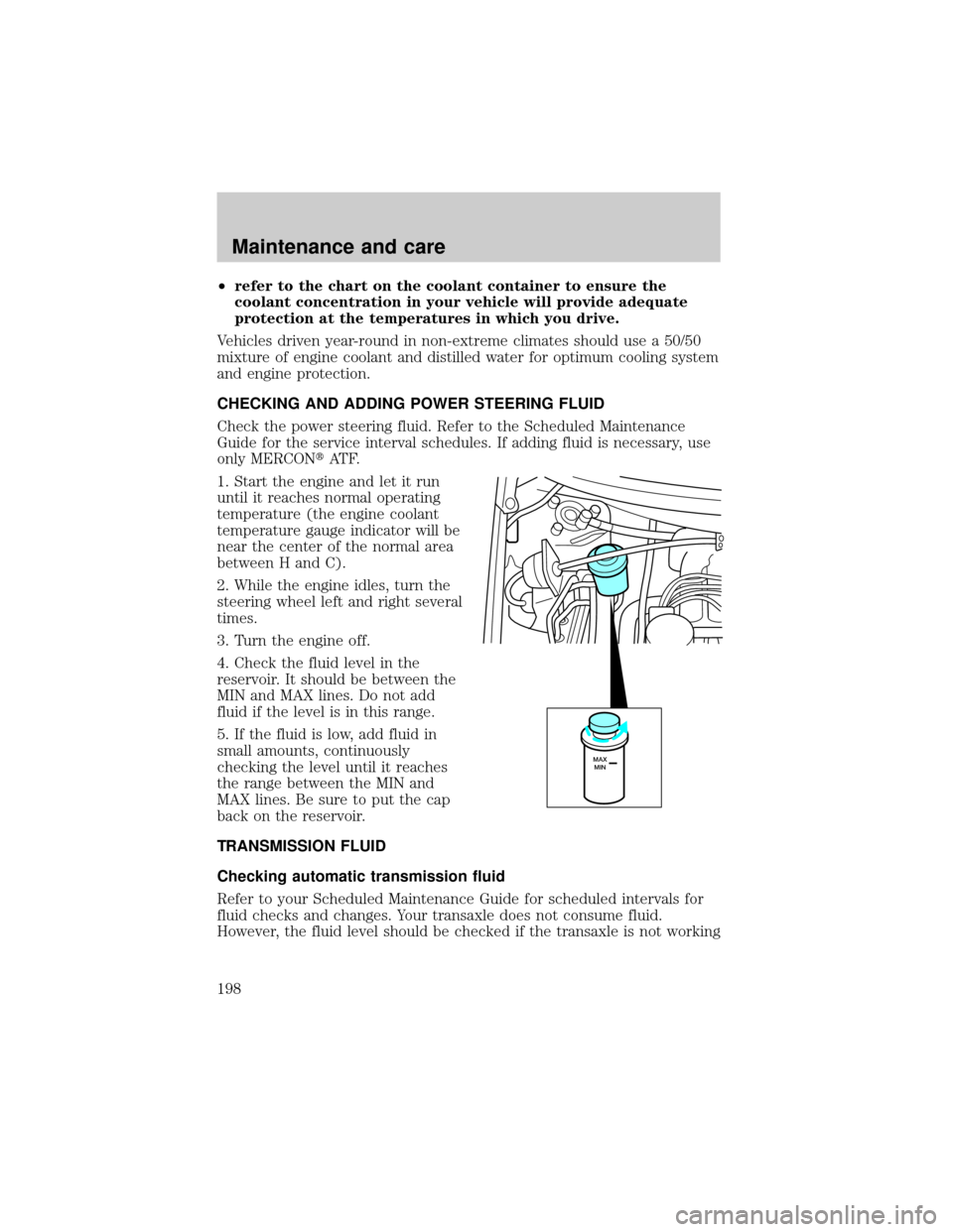
CHECKING AND ADDING POWER STEERING FLUID
Check the power steering fluid. Refer to the Scheduled Maintenance
Guide for the service interval schedules. If adding fluid is necessary, use
only MERCONtAT F.
1. Start the engine and let it run
until it reaches normal operating
temperature (the engine coolant
temperature gauge indicator will be
near the center of the normal area
between H and C).
2. While the engine idles, turn the
steering wheel left and right several
times.
3. Turn the engine off.
4. Check the fluid level in the
reservoir. It should be between the
MIN and MAX lines. Do not add
fluid if the level is in this range.
5. If the fluid is low, add fluid in
small amounts, continuously
checking the level until it reaches
the range between the MIN and
MAX lines. Be sure to put the cap
back on the reservoir.
TRANSMISSION FLUID
Checking automatic transmission fluid
Refer to your Scheduled Maintenance Guide for scheduled intervals for
fluid checks and changes. Your transaxle does not consume fluid.
However, the fluid level should be checked if the transaxle is not working
MAX
MIN
Maintenance and care
198