warning light Mercury Villager 2002 Owner's Manuals
[x] Cancel search | Manufacturer: MERCURY, Model Year: 2002, Model line: Villager, Model: Mercury Villager 2002Pages: 256, PDF Size: 1.91 MB
Page 1 of 256
Introduction 4
Instrument Cluster 10
Warning and control lights 10
Gauges 15
Entertainment Systems 20
AM/FM stereo cassette (CD changer compatible) 20
AM/FM stereo cassette with CD 39
Rear seat controls 50
CD changer 53
Climate Controls 58
Manual heating and air conditioning 58
Electronic automatic temperature control 63
Lights 74
Headlamps 74
Turn signal control 76
Bulb replacement 77
Driver Controls 83
Windshield wiper/washer control 83
Steering wheel adjustment 85
Power windows 87
Mirrors 89
Speed control 90
Message center 99
Locks and Security 108
Keys 108
Locks 108
Anti-theft system 109
Table of Contents
1
Page 5 of 256
Additional owner information is given in separate publications.
This Owner’s Guide describes every option and model variant available
and therefore some of the items covered may not apply to your
particular vehicle. Furthermore, due to printing cycles it may describe
options before they are generally available.
Remember to pass on the Owner’s Guide when reselling the vehicle. It is
an integral part of the vehicle.
Fuel pump shut-off switchIn the event of an accident the
safety switch will automatically cut off the fuel supply to the
engine. The switch can also be activated through sudden vibration (e.g.
collision when parking). To reset the switch, refer to theFuel pump
shut-off switchin theRoadside emergencieschapter.
SAFETY AND ENVIRONMENT PROTECTION
Warning symbols in this guide
How can you reduce the risk of personal injury and prevent possible
damage to others, your vehicle and its equipment? In this guide, answers
to such questions are contained in comments highlighted by the warning
triangle symbol. These comments should be read and observed.
Warning symbols on your vehicle
When you see this symbol, it is
imperative that you consult the
relevant section of this guide before
touching or attempting adjustment
of any kind.
Introduction
5
Page 8 of 256
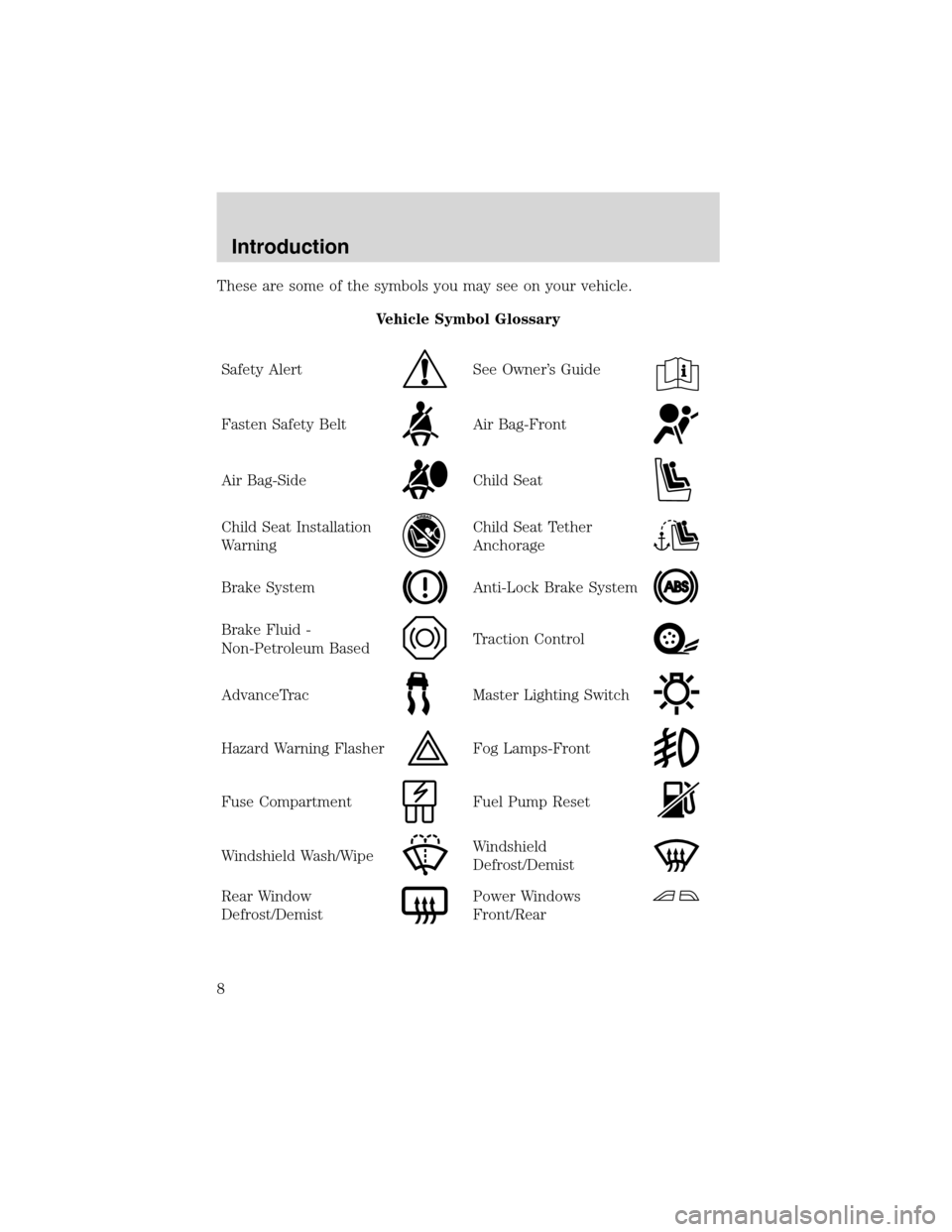
These are some of the symbols you may see on your vehicle.
Vehicle Symbol Glossary
Safety Alert
See Owner’s Guide
Fasten Safety BeltAir Bag-Front
Air Bag-SideChild Seat
Child Seat Installation
WarningChild Seat Tether
Anchorage
Brake SystemAnti-Lock Brake System
Brake Fluid -
Non-Petroleum BasedTraction Control
AdvanceTracMaster Lighting Switch
Hazard Warning FlasherFog Lamps-Front
Fuse CompartmentFuel Pump Reset
Windshield Wash/WipeWindshield
Defrost/Demist
Rear Window
Defrost/DemistPower Windows
Front/Rear
Introduction
8
Page 10 of 256
WARNING LIGHTS AND CHIMES
Warning lights and gauges can alert you to a vehicle condition that may
become serious enough to cause expensive repairs. A warning light may
illuminate when a problem exists with one of your vehicle’s functions.
Many lights will illuminate when you start your vehicle to make sure the
bulb works.If any light remains on after starting the vehicle, have
the respective system inspected immediately.
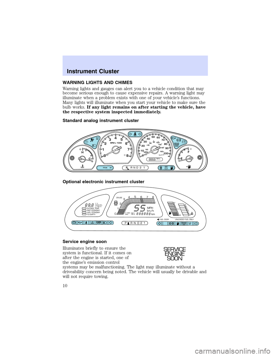
Standard analog instrument cluster
Optional electronic instrument cluster
Service engine soon
Illuminates briefly to ensure the
system is functional. If it comes on
after the engine is started, one of
the engine’s emission control
systems may be malfunctioning. The light may illuminate without a
driveability concern being noted. The vehicle will usually be drivable and
will not require towing.
km/h0 1020304050
60
70
80
90
100MPH
TRIP A
RPM x 1000
20406080
100
120
140
160
0 1234
5
6
7
8F
H
CE
CRUISE SETPRND2P1
SERVICE
ENGINE
SOONABSAIR
BAGABSO/D
OFF
OUTSIDE TEMP
INST ECONOMY
AVG. ECONOMY
TO EMPTY
PRND21FUEL DOOR UNLEADED FUEL ONLY CRUISE
MPH
km/h
km
F
EH
C
1/2N
O
R
M
A
L
012345
6
78
P!BRAKE
X 1000
RPMTRIP 1
TRIP 2 ˚F ˚C
MILES/BAL
L/100 km
SERVICE
ENGINE
SOON
Instrument Cluster
10
Page 11 of 256
Light turns on solid:
Temporary malfunctions may cause the light to illuminate. Examples are:
1. The vehicle has run out of fuel.
2. Poor fuel quality or water in the fuel.
3. The fuel cap may not have been properly installed and securely
tightened.
These temporary malfunctions can be corrected by filling the fuel tank
with high quality fuel of the recommended octane and/or properly
installing and securely tightening the fuel cap. After three driving cycles
without these or any other temporary malfunctions present, the light
should turn off. (A driving cycle consists of a cold engine startup
followed by mixed city/highway driving.) No additional vehicle service is
required.
If the light remains on, have your vehicle serviced at the first available
opportunity.
Light is blinking:
Engine misfire is occurring which could damage your catalytic converter.
You should drive in a moderate fashion (avoid heavy acceleration and
deceleration) and have your vehicle serviced at the first available
opportunity.
Under engine misfire conditions, excessive exhaust temperatures
could damage the catalytic converter, the fuel system, interior
floor coverings or other vehicle components, possibly causing a fire.
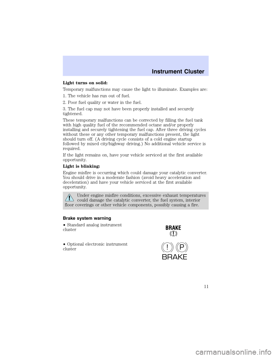
Brake system warning
•Standard analog instrument
cluster
•Optional electronic instrument
cluster
P!
BRAKE
Instrument Cluster
11
Page 12 of 256
To confirm the brake system warning light is functional, it will
momentarily illuminate when the ignition is turned to the ON position
(alternatively for some vehicles when the ignition is moved from the ON
position to START position, the light will momentarily illuminate prior to
reaching the START position). It also illuminates if the parking brake is
engaged. If the brake system warning light does not illuminate as
described, seek service immediately. Illumination after the parking brake
is released indicates low brake fluid level or a brake system malfunction
and the brake system should be serviced immediately by a qualified
technician. Refer toBrakesin theDrivingchapter for more information.
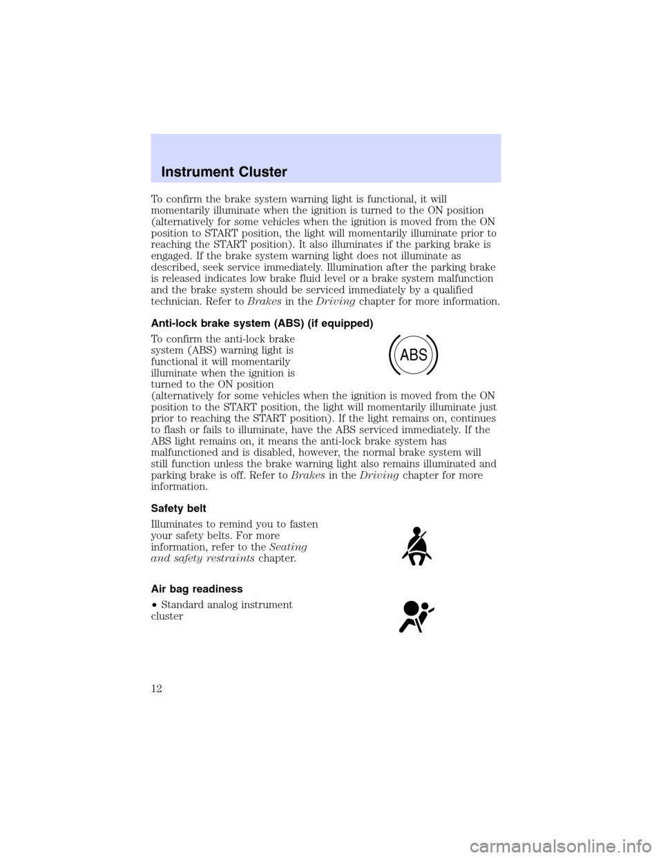
Anti-lock brake system (ABS) (if equipped)
To confirm the anti-lock brake
system (ABS) warning light is
functional it will momentarily
illuminate when the ignition is
turned to the ON position
(alternatively for some vehicles when the ignition is moved from the ON
position to the START position, the light will momentarily illuminate just
prior to reaching the START position). If the light remains on, continues
to flash or fails to illuminate, have the ABS serviced immediately. If the
ABS light remains on, it means the anti-lock brake system has
malfunctioned and is disabled, however, the normal brake system will
still function unless the brake warning light also remains illuminated and
parking brake is off. Refer toBrakesin theDrivingchapter for more
information.
Safety belt
Illuminates to remind you to fasten
your safety belts. For more
information, refer to theSeating
and safety restraintschapter.
Air bag readiness
•Standard analog instrument
cluster
ABS
Instrument Cluster
12
Page 135 of 256
Safety belt warning light and indicator chime
The seat belt warning light illuminates in the instrument cluster and a
chime sounds to remind the occupants to fasten their safety belts.
Conditions of operation
If... Then...
The driver’s safety belt is not
buckled before the ignition
switch is turned to the ON
position...The safety belt warning light
illuminates until safety belt is buckled.
The driver’s safety belt is
buckled while the indicator
light is illuminated and the
warning chime is sounding...The safety belt warning light and
warning chime turn off.
The driver’s safety belt is
buckled before the ignition
switch is turned to the ON
position...The safety belt warning light and
indicator chime remain off.
Safety belt extension assembly
If the safety belt is too short when fully extended, there is a 20 cm (8
inch) safety belt extension assembly that can be added (part number
611C22). This assembly can be obtained from your dealer at no cost.
Use only extensions manufactured by the same supplier as the safety
belt. Manufacturer identification is located at the end of the webbing on
the label. Also, use the safety belt extension only if the safety belt is too
short for you when fully extended.
Do not use extensions to change the fit of the shoulder belt across the
torso.
Safety belt maintenance
Inspect the safety belt systems periodically to make sure they work
properly and are not damaged. Inspect the safety belts to make sure
there are no nicks, tears or cuts, replacing if necessary. All safety belt
assemblies, including retractors, buckles, front seat belt buckle
assemblies, buckle support assemblies (slide bar-if equipped), shoulder
belt height adjusters (if equipped), shoulder belt guide on seatback (if
equipped), LATCH child safety seat tether anchors and lower anchors,
Seating and Safety Restraints
135
Page 140 of 256

If the air bag has deployed,the air bag will not function
again and must be replaced immediately.If the air bag is not
replaced, the unrepaired area will increase the risk of injury in a
collision.
The SRS consists of:
•driver and passenger air bag modules (which include the inflators and
air bags),
•one or more impact and safing sensors,
•a readiness light
•and the electrical wiring which connects the components.
The diagnostic module monitors its own internal circuits and the
supplemental air bag electrical system warning (including the impact
sensors), the system wiring, the air bag system readiness light, the air
bag back up power and the air bag ignitors.
Determining if the system is operational
The SRS uses a readiness light in the instrument cluster to indicate the
condition of the system. Refer to theAir bag readinesssection in the
Instrument clusterchapter. Routine maintenance of the air bag is not
required.
A difficulty with the system is indicated by one or more of the following:
•The readiness light will either
flash or stay lit.
•The readiness light will not
illuminate immediately after
ignition is turned on.
If any of these things happen, even intermittently, have the SRS serviced
at your dealership or by a qualified technician immediately. Unless
serviced, the system may not function properly in the event of a
collision.
Disposal of air bags and air bag equipped vehicles (including
pretensioners)
For disposal of air bags or air bag equipped vehicles, see your local
dealership or qualified technician. Air bags MUST BE disposed of by
qualified personnel.
AIR
BAG
Seating and Safety Restraints
140
Page 155 of 256

STARTING
Positions of the ignition
1. OFF/LOCK, shuts off the engine
and all accessories/locks the steering
wheel, gearshift lever and allows key
removal.
2. ACC, allows the electrical
accessories such as the radio to
operate while the engine is not
running.
3. ON, all electrical circuits
operational. Warning lights
illuminated. Key position when driving.
4. START, cranks the engine. Release the key as soon as the engine
starts.
Preparing to start your vehicle
Engine starting is controlled by the powertrain control system. This
system meets all Canadian Interference-Causing Equipment standard
requirements regulating the impulse electrical field strength of radio
noise.
When starting a fuel-injected engine, avoid pressing the accelerator
before or during starting. Only use the accelerator when you have
difficulty starting the engine. For more information on starting the
vehicle, refer toStarting the enginein this chapter.
Extended idling at high engine speeds can produce very high
temperatures in the engine and exhaust system, creating the risk
of fire or other damage.
Do not park, idle, or drive your vehicle in dry grass or other dry
ground cover. The emission system heats up the engine
compartment and exhaust system, which can start a fire.
Do not start your vehicle in a closed garage or in other enclosed
areas. Exhaust fumes can be toxic. Always open the garage door
before you start the engine. SeeGuarding against exhaust fumesin
this chapter for more instructions.
4
3
2
1
Driving
155
Page 159 of 256
Occasional brake noise is normal and often does not indicate a
performance concern with the vehicle’s brake system. In normal
operation, automotive brake systems may emit occasional or intermittent
squeal or groan noises when the brakes are applied. Such noises are
usually heard during the first few brake applications in the morning;
however, they may be heard at any time while braking and can be
aggravated by environmental conditions such as cold, heat, moisture,
road dust, salt or mud. If a“metal-to-metal,”“continuous grinding”or
“continuous squeal”sound is present while braking, the brake linings
may be worn-out and should be inspected by a qualified service
technician.
If you are driving down a long or steep hill, shift to a lower gear.
Do not apply your brakes continuously, as they may overheat
and become less effective.
Anti-lock brake system (ABS) (if equipped)
On vehicles equipped with an anti-lock braking system (ABS), a noise
from the hydraulic pump motor and pulsation in the pedal may be
observed during ABS braking events. Pedal pulsation coupled with noise
while braking under panic conditions or on loose gravel, bumps, wet or
snowy roads is normal and indicates proper functioning of the vehicle’s
anti-lock brake system. The ABS performs a self-check after you start
the engine and begin to drive away. A brief mechanical noise may be
heard during this test. This is normal. If a malfunction is found, the ABS
warning light will come on. If the vehicle has continuous vibration or
shudder in the steering wheel while braking, the vehicle should be
inspected by a qualified service technician.
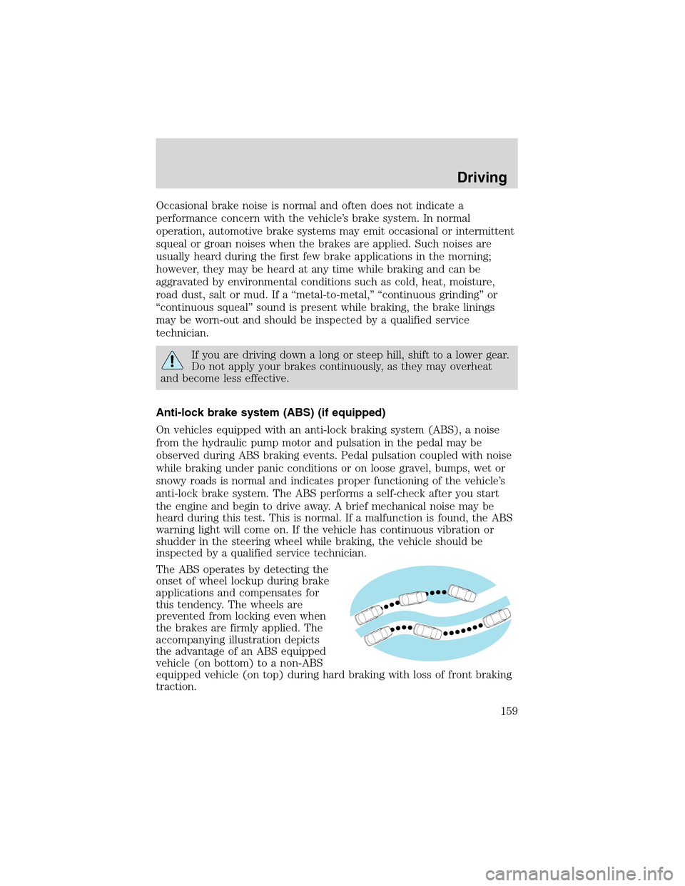
The ABS operates by detecting the
onset of wheel lockup during brake
applications and compensates for
this tendency. The wheels are
prevented from locking even when
the brakes are firmly applied. The
accompanying illustration depicts
the advantage of an ABS equipped
vehicle (on bottom) to a non-ABS
equipped vehicle (on top) during hard braking with loss of front braking
traction.
Driving
159