lock MINI 3 door 2014 Owner's Guide
[x] Cancel search | Manufacturer: MINI, Model Year: 2014, Model line: 3 door, Model: MINI 3 door 2014Pages: 240, PDF Size: 11.05 MB
Page 98 of 240
Ejection MitigationThe system consists of an extension of the head
airbag system and is a kind of curtain. The sys‐
tem is activated under certain conditions in the
event of a rollover accident, and should help to
prevent the vehicle occupant from being
thrown out of the vehicle.
Knee airbag
The knee airbag supports the legs in a frontal
impact.
Protective action
Airbags are not triggered in every impact situa‐
tion, e.g., in less severe accidents or rear-end
collisions.
Information on how to ensure the opti‐
mal protective effect of the airbags▷Keep at a distance from the airbags.▷Always grasp the steering wheel on the
steering wheel rim, holding your hands at
the 3 o'clock and 9 o'clock positions, to
keep the risk of injury to your hands or
arms as low as possible when the airbag is
triggered.▷There should be no person, animals, or ob‐
jects between an airbag and a person.▷Do not use the cover of the front airbag on
the front passenger side as a storage area.▷Dashboard and windshield on the front
passenger side must stay clear - do not at‐
tach adhesive labels or coverings and do
not attach brackets or cables, e. g., for GPS
devices or' mobile phones.▷Make sure that the front passenger is sitting
correctly, i.e., keeps his or her feet and legs
in the footwell; otherwise, leg injuries might
occur when front airbag is activated.▷Do not place slip covers, seat cushions or
other objects on the front passenger seat
that are not approved specifically for seats
with integrated side airbags.▷Do not hang pieces of clothing, such as
jackets, over the backrests.▷Make sure that occupants keep their heads
away from the side airbag and do not rest
against the head airbag; otherwise, injuries
might occur when airbag is activated.▷Do not remove the airbag system.▷Do not remove the steering wheel.▷Do not apply adhesive materials to the air‐
bag cover panels, do not cover them or
modify them in any way.▷Never modify either the individual compo‐
nents or the wiring in the airbag system.
This also applies to steering wheel covers,
the dashboard, the seats, the roof pillars
and the sides of the roofliner. ◀
Even when you follow all instructions very
closely, injury from contact with the airbags
cannot be ruled out in certain situations.
The ignition and inflation noise may lead to
short-term and, in most cases, temporary hear‐
ing impairment in sensitive individuals.
Malfunction, deactivation and after de‐
ploying the airbags
Do not touch the individual components imme‐
diately after the system has been triggered;
otherwise, you may risk burns.
Only have the airbags checked, repaired or dis‐
mantled and the airbag generator scrapped by
the service center or an authorized repair shop
for handling explosives.
Non-professional attempts to service the sys‐
tem could lead to failure in an emergency or
unintentional activation of the airbag - both
may lead to injury. ◀
Warnings and information on the airbags are
also found on the sun visors.
Seite 94CONTROLSSafety94
Online Edition for Part no. 01 40 2 957 280 - X/14
Page 113 of 240
Driving stability control systemsVehicle features and op‐
tions
This chapter describes all standard, country-
specific and optional features offered with the
series. It also describes features that are not
necessarily available in your car, e. g., due to
the selected options or country versions. This
also applies to safety-related functions and sys‐
tems.
Antilock Brake System
ABS
ABS prevents locking of the wheels duringbraking.
The vehicle contains its steering power even
during full brake applications, thus increasing
active safety.
ABS is operational every time you start the en‐
gine.
Brake assistant
When you apply the brakes rapidly, this system
automatically produces the greatest possible
braking force boost. It reduces the braking dis‐
tance to a minimum during emergency stop. This system utilizes all of the benefits provided
by ABS.
Do not reduce the pressure on the brake pedal
for the duration of the emergency stop.DSC Dynamic Stability
Control
The concept
DSC prevents traction loss in the power wheels
when driving off and accelerating.
DSC also recognizes unstable vehicle conditions
such as fishtailing or nose-diving. Within the
physical limits DSC helps to keep the vehicle on
a steady course by reducing engine speed and
by applying brakes to the individual wheels.
Adjust your driving style to the situationAn appropriate driving style is always the
responsibility of the driver.
The laws of physics cannot be repealed, not
even with DSC.
Therefore, do not reduce the additional safety
margin by driving in a risky manner. ◀
Indicator/warning lights The indicator lamp flashes: DSC controls
the drive and braking forces.
The indicator lamp lights up: DSC has
failed.
Deactivating DSC: DSC OFF
When DSC is deactivated, driving stability is re‐
duced during acceleration and when driving in
curves.
To increase vehicle stability, activate DSC again
as soon as possible.
Deactivating DSC Press and hold this button but not lon‐
ger than approx. 10 seconds, until the
indicator lamp for DSC OFF lights up in the in‐
strument cluster and displays DSC OFF.Seite 109Driving stability control systemsCONTROLS109
Online Edition for Part no. 01 40 2 957 280 - X/14
Page 135 of 240
Climate control functions in detail
Manual air distribution Turn the wheel to select the de‐
sired program or the desired in‐
termediate setting.▷ Windows.▷ Upper body region.▷ Footwell.▷ Windows, upper body region, and foot‐
well.
Defrosts windows and removes
condensation
Direct the air distribution toward windows, in‐
crease the air flow and temperature, and, if
needed, use the cooling function.
Air flow, manual Turn the ring to set the desired
air volume.
The higher the rate, the more ef‐
fective the heating or cooling will
be.
The air flow from the air conditioner may be re‐
duced automatically to save battery power.
Temperature Turn the ring to set the desired
temperature.
Cooling function The car's interior can only be cooled with the
engine running.
Press button.
The air will be cooled and dehumidified and,
depending on the temperature setting,
warmed again.
Depending on the weather, the windshield may
fog up briefly when the engine is started.
The air conditioner produces condensation wa‐
ter, refer to page 154, that will exit from below
the car.
Recirculated-air mode You may respond to unpleasant odors or pollu‐
tants in the immediate environment by tempo‐
rarily suspending the supply of outside air. The
system then recirculates the air currently within
the vehicle.
Press button repeatedly to select an
operating mode:▷LED off: outside air flows in continuously.▷LED on, recirculated-air mode: the supply
of outside air into the vehicle is perma‐
nently blocked.
Recirculated air mode switches off automati‐
cally at low external temperatures after a cer‐
tain amount of time in order to avoid window
fogging.
If the windows fog over, reel off recirculated-air
mode and increase the air flow, if needed.
Sufficient ventilation
When remaining in the vehicle for an ex‐
tended period of time, ensure sufficient exter‐
nal ventilation. Do not continuously use recircu‐
lated-air mode; otherwise the air quality in the
interior continuously worsens. ◀
Rear window defroster Press button.
The rear window defroster switches off
automatically after a certain period of time.
When Green mode, refer to page 160, is acti‐
vated, the heater output is reduced.
Seite 131Climate controlCONTROLS131
Online Edition for Part no. 01 40 2 957 280 - X/14
Page 138 of 240
▷Windows.
Maximum coolingPress button.
The system is set to the lowest temper‐
ature, maximum air flow and recirculated-air
mode.
Air flows out of the vents to the upper body re‐
gion. The vents need to be open for this.
The function is available with external tempera‐
tures beyond approx. 32 ℉/0 ℃ and with the
engine running.
Adjust air flow with the program active.
Cooling function The car's interior can only be cooled with the
engine running.
Press button.
The air will be cooled and dehumidi‐
fied and, depending on the temperature set‐
ting, warmed again.
Depending on the weather, the windshield may
fog up briefly when the engine is started.
The cooling function is switched on automati‐
cally with the AUTO program.
When using the automatic climate control, con‐
densation water, refer to page 154, develops
that exits underneath the vehicle.
Automatic recirculated-air control/
recirculated-air mode
You may respond to unpleasant odors or pollu‐
tants in the immediate environment by tempo‐
rarily suspending the supply of outside air. The
system then recirculates the air currently within
the vehicle.
Press button repeatedly to select an
operating mode:
▷LEDs off: outside air flows in continuously.▷Left LED on, automatic recirculated-air con‐
trol: a sensor detects pollutants in the out‐
side air and shuts off automatically.▷Right LED on, recirculated-air mode: the
supply of outside air into the vehicle is per‐
manently blocked.
Recirculated air mode switches off automati‐
cally at low external temperatures after a cer‐
tain amount of time in order to avoid window
fogging.
If windows are fogged over, reel off the recircu‐
lating mode and press the AUTO button. Make
sure that air can flow to the windshield.
Sufficient ventilation
When remaining in the vehicle for an ex‐
tended period of time, ensure sufficient exter‐
nal ventilation. Do not continuously use recircu‐
lated-air mode; otherwise the air quality in the
interior continuously worsens. ◀
Rear window defroster Press button.
The rear window defroster switches off
automatically after a certain period of time.
When Green mode, refer to page 160, is acti‐
vated, the heater output is reduced.
Windshield defroster Press button.
The front window defroster switches
off automatically after a certain period of time.
Defrosts windows and removes
condensation
Press button.
Ice and condensation are quickly re‐
moved from the windshield and the front side
windows.
Adjust air flow with the program active.
Seite 134CONTROLSClimate control134
Online Edition for Part no. 01 40 2 957 280 - X/14
Page 147 of 240
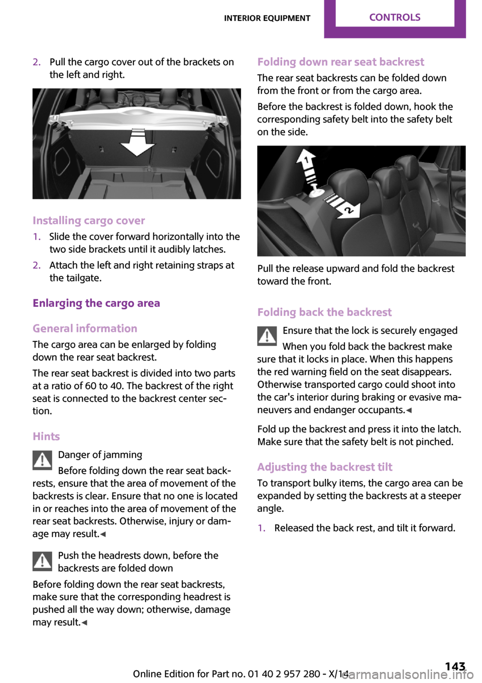
2.Pull the cargo cover out of the brackets on
the left and right.
Installing cargo cover
1.Slide the cover forward horizontally into the
two side brackets until it audibly latches.2.Attach the left and right retaining straps at
the tailgate.
Enlarging the cargo area
General information
The cargo area can be enlarged by folding
down the rear seat backrest.
The rear seat backrest is divided into two parts
at a ratio of 60 to 40. The backrest of the right
seat is connected to the backrest center sec‐
tion.
Hints Danger of jamming
Before folding down the rear seat back‐
rests, ensure that the area of movement of the
backrests is clear. Ensure that no one is located
in or reaches into the area of movement of the
rear seat backrests. Otherwise, injury or dam‐
age may result. ◀
Push the headrests down, before the
backrests are folded down
Before folding down the rear seat backrests,
make sure that the corresponding headrest is
pushed all the way down; otherwise, damage
may result. ◀
Folding down rear seat backrest
The rear seat backrests can be folded down
from the front or from the cargo area.
Before the backrest is folded down, hook the
corresponding safety belt into the safety belt
on the side.
Pull the release upward and fold the backrest
toward the front.
Folding back the backrest Ensure that the lock is securely engaged
When you fold back the backrest make
sure that it locks in place. When this happens
the red warning field on the seat disappears.
Otherwise transported cargo could shoot into
the car's interior during braking or evasive ma‐
neuvers and endanger occupants. ◀
Fold up the backrest and press it into the latch.
Make sure that the safety belt is not pinched.
Adjusting the backrest tilt To transport bulky items, the cargo area can be
expanded by setting the backrests at a steeper
angle.
1.Released the back rest, and tilt it forward.Seite 143Interior equipmentCONTROLS143
Online Edition for Part no. 01 40 2 957 280 - X/14
Page 152 of 240
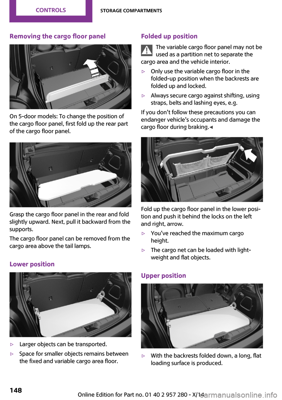
Removing the cargo floor panel
On 5-door models: To change the position of
the cargo floor panel, first fold up the rear part
of the cargo floor panel.
Grasp the cargo floor panel in the rear and fold
slightly upward. Next, pull it backward from the
supports.
The cargo floor panel can be removed from the
cargo area above the tail lamps.
Lower position
▷Larger objects can be transported.▷Space for smaller objects remains between
the fixed and variable cargo area floor.Folded up position
The variable cargo floor panel may not be
used as a partition net to separate the
cargo area and the vehicle interior.▷Only use the variable cargo floor in the
folded-up position when the backrests are
folded up and locked.▷Always secure cargo against shifting, using
straps, belts and lashing eyes, e.g.
If you don't follow these precautions you can
endanger vehicle's occupants and damage the
cargo floor during braking. ◀
Fold up the cargo floor panel in the lower posi‐
tion and push it behind the locks on the left
and right, arrow.
▷You've reached the maximum cargo
height.▷The cargo net can be loaded with light‐
weight and flat objects.
Upper position
▷With the backrests folded down, a long, flat
loading surface is produced.Seite 148CONTROLSStorage compartments148
Online Edition for Part no. 01 40 2 957 280 - X/14
Page 172 of 240
RefuelingVehicle features and op‐
tions
This chapter describes all standard, country-
specific and optional features offered with the
series. It also describes features that are not necessarily available in your car, e. g., due to
the selected options or country versions. This
also applies to safety-related functions and sys‐
tems.
General information Refuel promptly
Refuel no later than at a range of
30 miles/50 km or engine operation might fail
and damage might occur. ◀
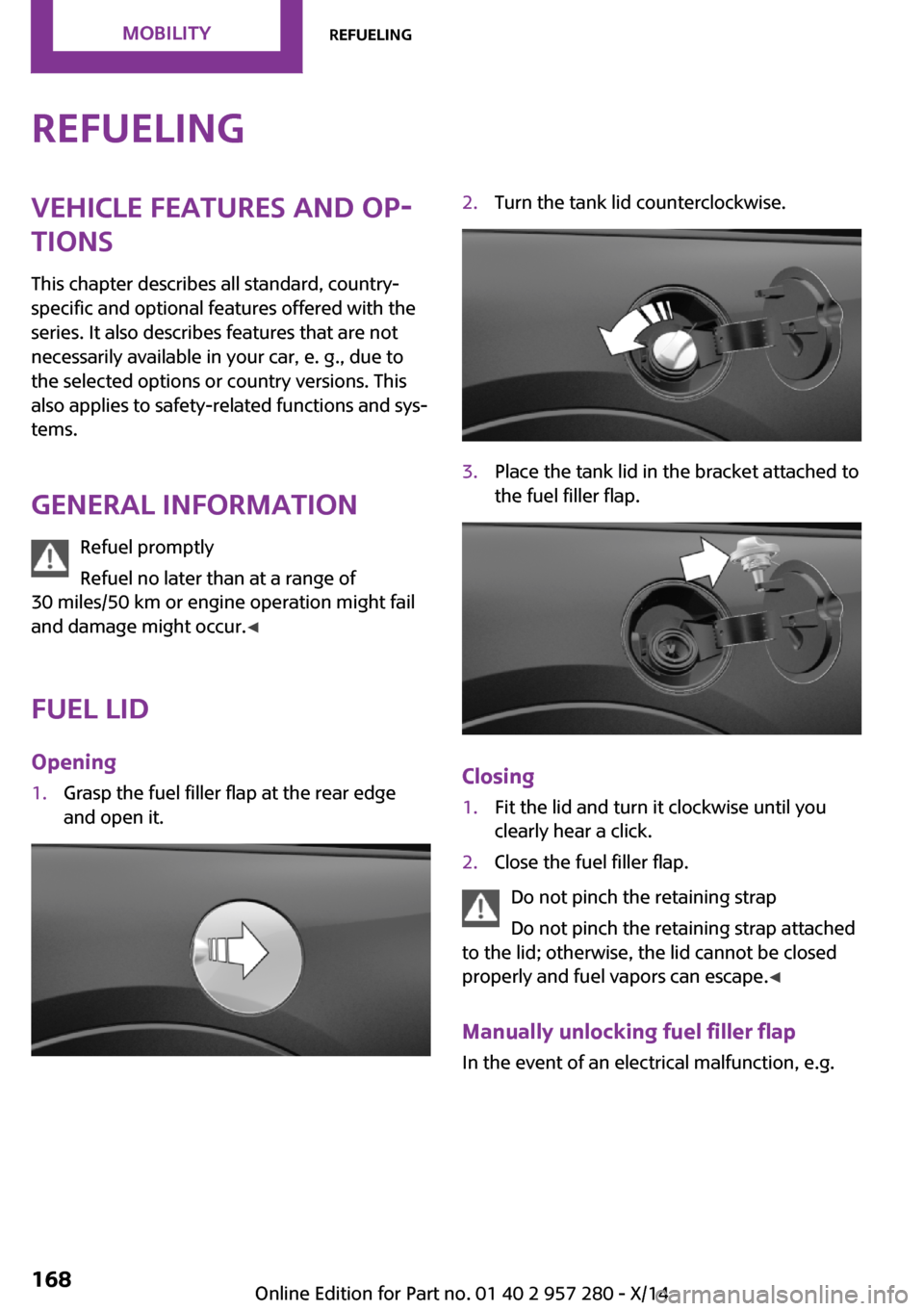
Fuel lid Opening1.Grasp the fuel filler flap at the rear edge
and open it.2.Turn the tank lid counterclockwise.3.Place the tank lid in the bracket attached to
the fuel filler flap.
Closing
1.Fit the lid and turn it clockwise until you
clearly hear a click.2.Close the fuel filler flap.
Do not pinch the retaining strap
Do not pinch the retaining strap attached
to the lid; otherwise, the lid cannot be closed
properly and fuel vapors can escape. ◀
Manually unlocking fuel filler flap
In the event of an electrical malfunction, e.g.
Seite 168MOBILITYRefueling168
Online Edition for Part no. 01 40 2 957 280 - X/14
Page 185 of 240
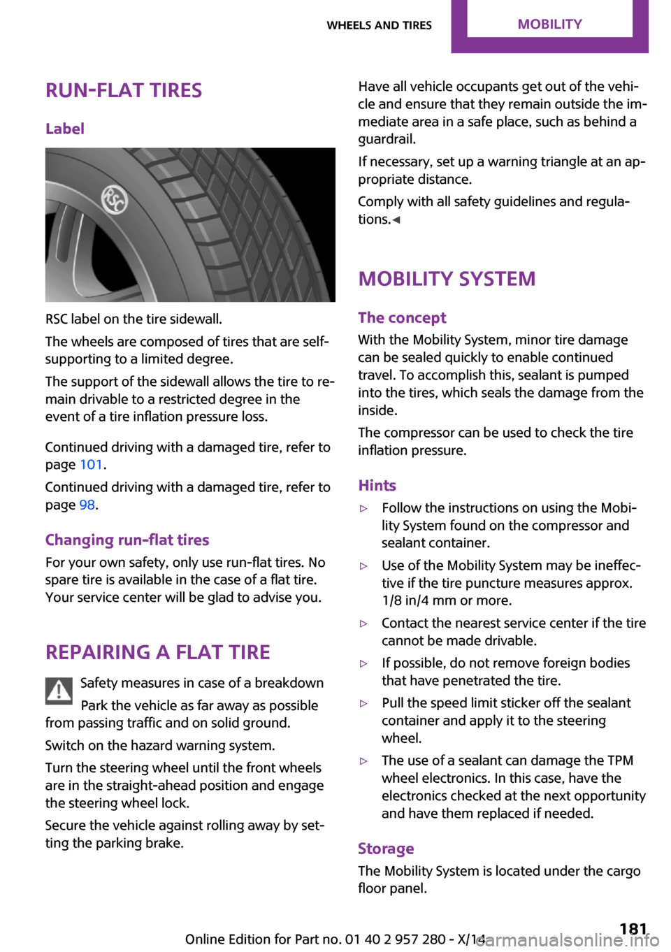
Run-flat tiresLabel
RSC label on the tire sidewall.
The wheels are composed of tires that are self-
supporting to a limited degree.
The support of the sidewall allows the tire to re‐
main drivable to a restricted degree in the
event of a tire inflation pressure loss.
Continued driving with a damaged tire, refer to
page 101.
Continued driving with a damaged tire, refer to
page 98.
Changing run-flat tires
For your own safety, only use run-flat tires. No
spare tire is available in the case of a flat tire.
Your service center will be glad to advise you.
Repairing a flat tire Safety measures in case of a breakdown
Park the vehicle as far away as possible
from passing traffic and on solid ground.
Switch on the hazard warning system.
Turn the steering wheel until the front wheels
are in the straight-ahead position and engage
the steering wheel lock.
Secure the vehicle against rolling away by set‐
ting the parking brake.
Have all vehicle occupants get out of the vehi‐
cle and ensure that they remain outside the im‐
mediate area in a safe place, such as behind a
guardrail.
If necessary, set up a warning triangle at an ap‐
propriate distance.
Comply with all safety guidelines and regula‐
tions. ◀
Mobility System
The concept
With the Mobility System, minor tire damage
can be sealed quickly to enable continued travel. To accomplish this, sealant is pumped
into the tires, which seals the damage from the
inside.
The compressor can be used to check the tire
inflation pressure.
Hints▷Follow the instructions on using the Mobi‐
lity System found on the compressor and
sealant container.▷Use of the Mobility System may be ineffec‐
tive if the tire puncture measures approx.
1/8 in/4 mm or more.▷Contact the nearest service center if the tire
cannot be made drivable.▷If possible, do not remove foreign bodies
that have penetrated the tire.▷Pull the speed limit sticker off the sealant
container and apply it to the steering
wheel.▷The use of a sealant can damage the TPM
wheel electronics. In this case, have the
electronics checked at the next opportunity
and have them replaced if needed.
Storage
The Mobility System is located under the cargo
floor panel.
Seite 181Wheels and tiresMOBILITY181
Online Edition for Part no. 01 40 2 957 280 - X/14
Page 191 of 240
Never reach into the engine compart‐
ment
Never reach into spaces or gaps in the engine
compartment; otherwise, there is a risk of in‐
jury, e.g., from rotating or hot parts. ◀
Fold down wiper arm
Before opening the hood, ensure that the
wiper arms are against the windshield, or this
may result in damage. ◀
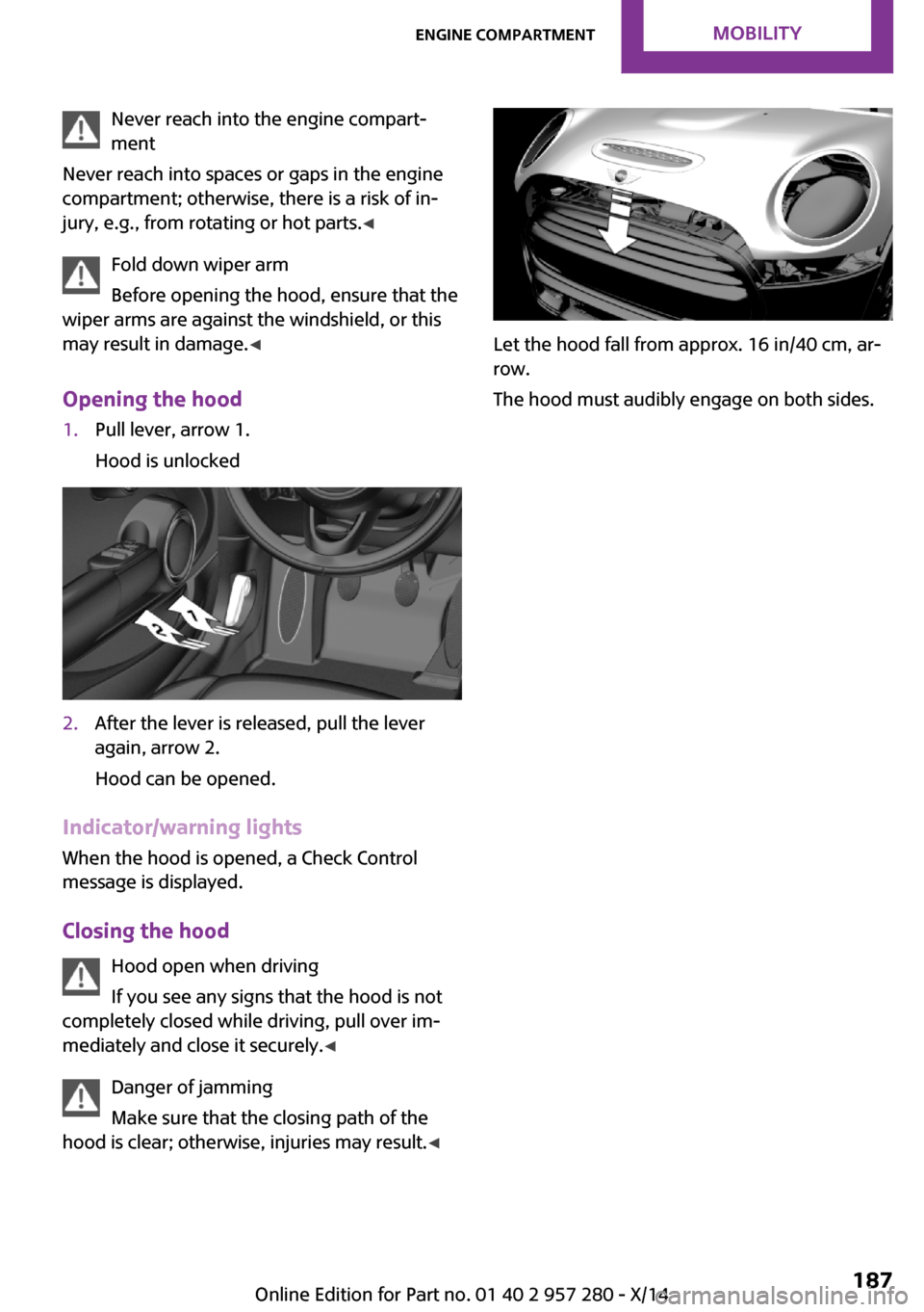
Opening the hood1.Pull lever, arrow 1.
Hood is unlocked2.After the lever is released, pull the lever
again, arrow 2.
Hood can be opened.
Indicator/warning lights
When the hood is opened, a Check Control
message is displayed.
Closing the hood Hood open when driving
If you see any signs that the hood is not
completely closed while driving, pull over im‐
mediately and close it securely. ◀
Danger of jamming
Make sure that the closing path of the
hood is clear; otherwise, injuries may result. ◀
Let the hood fall from approx. 16 in/40 cm, ar‐
row.
The hood must audibly engage on both sides.
Seite 187Engine compartmentMOBILITY187
Online Edition for Part no. 01 40 2 957 280 - X/14
Page 195 of 240
CoolantVehicle features and op‐
tions
This chapter describes all standard, country-
specific and optional features offered with the
series. It also describes features that are not
necessarily available in your car, e. g., due to
the selected options or country versions. This
also applies to safety-related functions and sys‐
tems.
General information Danger of burns from hot engine
Do not open the cooling system while the
engine is hot; otherwise, esliding coolant may
cause burns. ◀
Suitable additives
Only use suitable additives; otherwise,
engine damage may occur. The additives are
harmful to your health. ◀
Coolant consists of water and additives.
Not all commercially available additives are
suitable for your vehicle. Ask your service cen‐
ter for suitable additives.
Coolant level
Checking
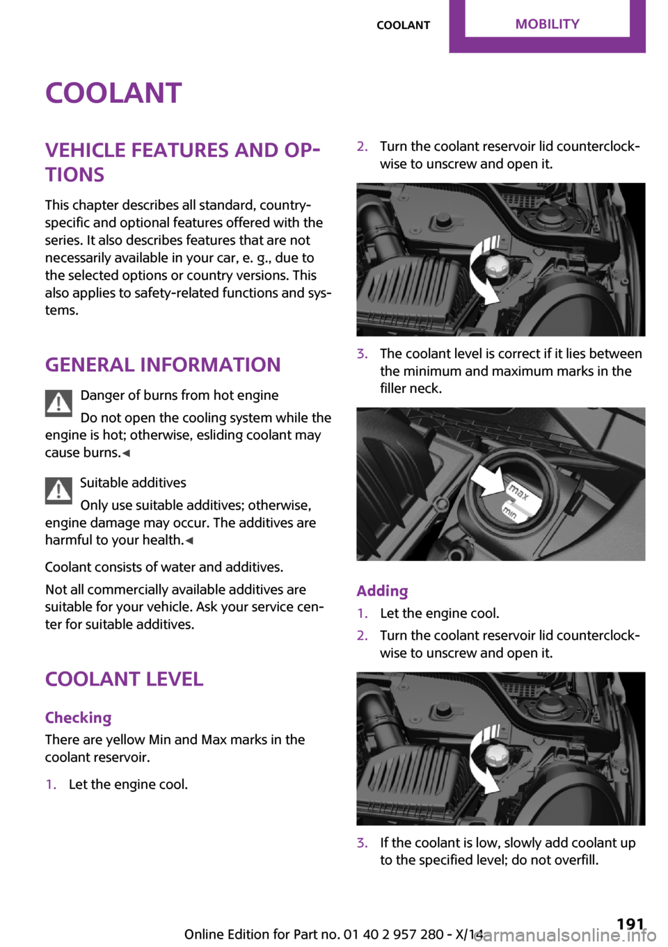
There are yellow Min and Max marks in the
coolant reservoir.1.Let the engine cool.2.Turn the coolant reservoir lid counterclock‐
wise to unscrew and open it.3.The coolant level is correct if it lies between
the minimum and maximum marks in the
filler neck.
Adding
1.Let the engine cool.2.Turn the coolant reservoir lid counterclock‐
wise to unscrew and open it.3.If the coolant is low, slowly add coolant up
to the specified level; do not overfill.Seite 191CoolantMOBILITY191
Online Edition for Part no. 01 40 2 957 280 - X/14