steering MINI 3 door 2014 Owner's Guide
[x] Cancel search | Manufacturer: MINI, Model Year: 2014, Model line: 3 door, Model: MINI 3 door 2014Pages: 240, PDF Size: 11.05 MB
Page 144 of 240
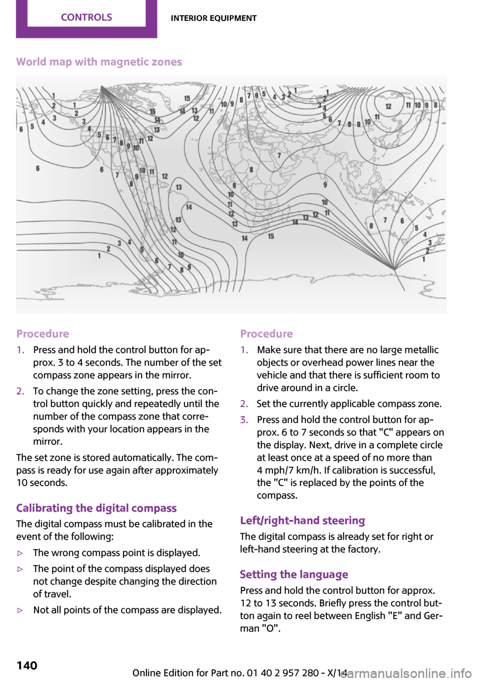
World map with magnetic zonesProcedure1.Press and hold the control button for ap‐
prox. 3 to 4 seconds. The number of the set
compass zone appears in the mirror.2.To change the zone setting, press the con‐
trol button quickly and repeatedly until the
number of the compass zone that corre‐
sponds with your location appears in the
mirror.
The set zone is stored automatically. The com‐
pass is ready for use again after approximately
10 seconds.
Calibrating the digital compass The digital compass must be calibrated in the
event of the following:
▷The wrong compass point is displayed.▷The point of the compass displayed does
not change despite changing the direction
of travel.▷Not all points of the compass are displayed.Procedure1.Make sure that there are no large metallic
objects or overhead power lines near the
vehicle and that there is sufficient room to
drive around in a circle.2.Set the currently applicable compass zone.3.Press and hold the control button for ap‐
prox. 6 to 7 seconds so that "C" appears on
the display. Next, drive in a complete circle
at least once at a speed of no more than
4 mph/7 km/h. If calibration is successful,
the "C" is replaced by the points of the
compass.
Left/right-hand steering
The digital compass is already set for right or
left-hand steering at the factory.
Setting the language
Press and hold the control button for approx.
12 to 13 seconds. Briefly press the control but‐ ton again to reel between English "E" and Ger‐
man "O".
Seite 140CONTROLSInterior equipment140
Online Edition for Part no. 01 40 2 957 280 - X/14
Page 157 of 240
Hot exhaust systemHot exhaust system
High temperatures are generated in the
exhaust system.
Do not remove the heat shields installed and
never apply undercoating to them. Make sure
that flammable materials, e. g. hay, leaves,
grass, etc. do not come in contact with the hot
exhaust system while driving, while in idle posi‐
tion mode, or when parked. Such contact could
lead to a fire, resulting in an increased risk of
serious personal injury as well as property dam‐
age.
Do not touch hot exhaust pipes; otherwise,
there is a danger of getting burned. ◀
Mobile communication devices in the
vehicle
Mobile communication devices in the ve‐hicle
It is not recommended to use mobile phones,
such as mobile phones, in the vehicle interior
without a direct connection to an external aer‐
ial. Otherwise, the vehicle's electronics and mo‐
bile communication devices can interfere with
each other. In addition, there is no assurance
that the radiation generated during transmis‐
sion will be conducted away from the vehicle
interior. ◀
Hydroplaning On wet or slushy roads, a wedge of water can
form between the tires and road surface.
This phenomenon is referred to as hydroplan‐
ing. It is characterized by a partial or complete
loss of contact between the tires and the road
surface, ultimately undermining your ability to
steer and brake the vehicle.
Hydroplaning
When driving on wet or slushy roads, re‐
duce your speed to prevent hydroplaning. ◀Driving through water
Drive through calm water only if it is not deeper
than 9.8 inches/25 cm and at this height, no
faster than walking speed, up to 3 mph/5 km/h.
Observe water level and speed
Do not exceed the maximum water level
and maximum speed; otherwise, the vehicle's
engine, the electrical systems and the transmis‐
sion may be damaged. ◀
Braking safely
Your vehicle is equipped with ABS as a standard
feature.
Applying the brakes fully is the most effective
way of braking in situations needed.
Steering is still responsive. You can still avoid
any obstacles with a minimum of steering ef‐
fort.
Pulsation of the brake pedal and sounds from
the hydraulic circuits indicate that ABS is in its
active mode.
Objects in the area around the pedals No objects in the area around the pedals
Keep floor mats, carpets, and any other
objects out of the pedal area; otherwise, the
function of the pedals could be impeded while
driving and create the risk of an accident.
Do not place additional floor mats over existing
mats or other objects.
Only use floor mats that have been approved for the vehicle and can be properly attached to
floor.
Ensure that the floor mats are securely fastened
again after they were removed for cleaning,
e.g. ◀
Driving in wet conditions When roads are wet or in heavy rain, press
brake pedal ever so gently every few miles.Seite 153Things to remember when drivingDRIVING TIPS153
Online Edition for Part no. 01 40 2 957 280 - X/14
Page 158 of 240
Ensure that this action does not endanger other
traffic.
The heat generated in this process helps dry
the brake discs and pads.
In this way braking efficiency will be available
when you need it.
HillsDrive long or steep downhill gradients in the
gear that requires least braking efforts. Other‐
wise the brakes may overheat and reduce
brake efficiency.
You can increase the engine's braking effect by
shifting down, going all the way to first gear, if
needed.
Avoid stressing the brakes
Avoid placing excessive stress on the
brake system. Light but consistent brake pres‐
sure can lead to high temperatures, brakes
wearing out and possibly even brake failure. ◀
Do not drive in neutral
Do not drive in neutral or with the engine
stopped, as doing so disables engine braking.
In addition, steering and brake assist are un‐
available with the engine stopped. ◀
Brake disc corrosion
Corrosion on the brake discs and contamina‐
tion on the brake pads are furthered by:▷Low mileage.▷Extended periods when the vehicle is not
used at all.▷Infrequent use of the brakes.
Corrosion will built up when the maximum
pressure applied to the brake pads during brak‐
ing is not reached - thus discs don't get
cleaned.
Corrosion buildup on the brake discs will cause
a pulsating effect on the brakes in their re‐
sponse - generally that cannot be corrected.
Condensation under the parked vehicle
When using the automatic climate control, con‐
densation water develops collecting under‐
neath the vehicle.
These traces of water under the vehicle are
normal.
Ground clearance Limited ground clearance
Observe the limited ground clearance of
the vehicle, e. g. while entering underground
parking garages or when driving over obsta‐
cles. Otherwise, damages to the vehicle may
result. ◀Seite 154DRIVING TIPSThings to remember when driving154
Online Edition for Part no. 01 40 2 957 280 - X/14
Page 161 of 240
Securing
Follow the installation instructions of the roof
rack.
Loading Be sure that adequate clearance is maintained
for tilting and opening the glass sunroof.
Because roof racks raise the vehicle's center of
gravity when loaded, they have a major effect
on vehicle handling and steering response.
Therefore, note the following when loading and
driving:▷Do not exceed the approved roof/axle
loads and the approved gross vehicle
weight.▷Distribute the roof load uniformly.▷The roof load should not extend past the
loading area.▷Always place the heaviest pieces on the
bottom.▷Secure the roof luggage firmly, e.g., tie with
ratchet straps.▷Do not let objects project into the opening
path of the tailgate.▷Drive cautiously and avoid sudden acceler‐
ation and braking maneuvers. Take corners
gently.
Rear luggage rack
General information Installation only possible with rear luggage rack
preparation.
Rear racks are available as special accessories.
Note Follow the installation instructions of the rear
luggage rack.
Drive cautiously and avoid sudden acceleration
and braking maneuvers. Take corners gently.
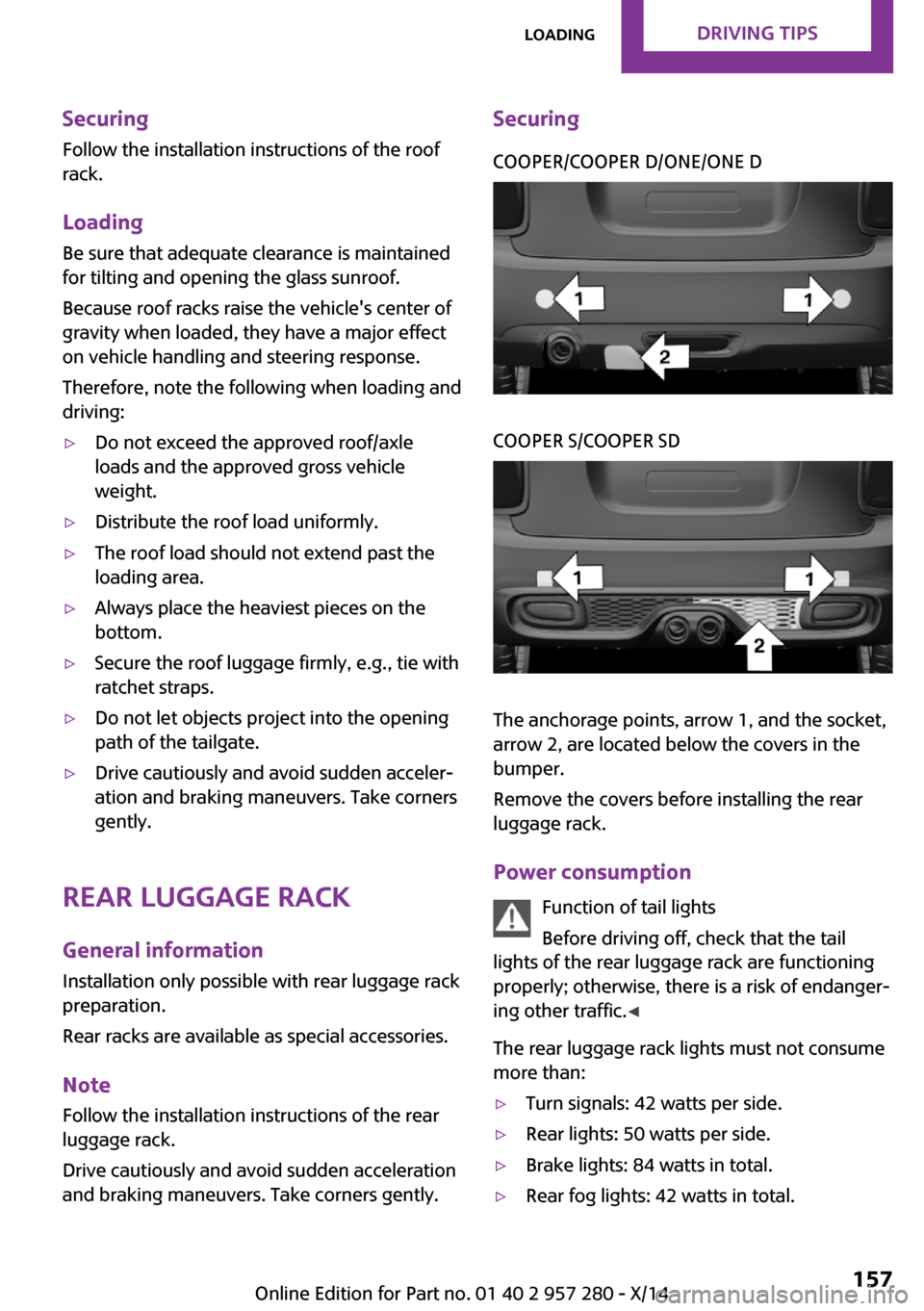
SecuringCOOPER/COOPER D/ONE/ONE DCOOPER S/COOPER SD
The anchorage points, arrow 1, and the socket,
arrow 2, are located below the covers in the
bumper.
Remove the covers before installing the rear
luggage rack.
Power consumption Function of tail lights
Before driving off, check that the tail
lights of the rear luggage rack are functioning
properly; otherwise, there is a risk of endanger‐
ing other traffic. ◀
The rear luggage rack lights must not consume
more than:
▷Turn signals: 42 watts per side.▷Rear lights: 50 watts per side.▷Brake lights: 84 watts in total.▷Rear fog lights: 42 watts in total.Seite 157LoadingDRIVING TIPS157
Online Edition for Part no. 01 40 2 957 280 - X/14
Page 185 of 240
Run-flat tiresLabel
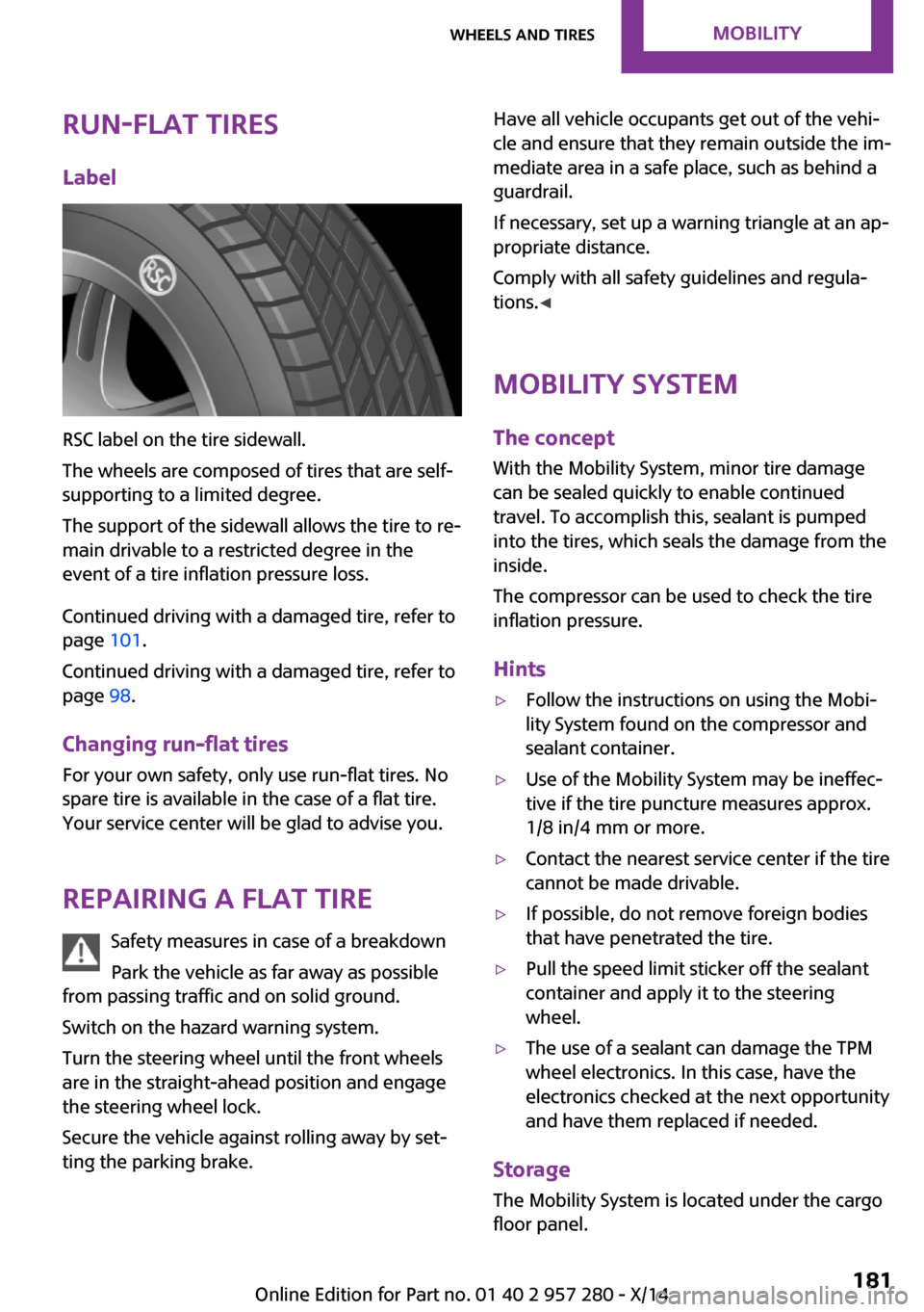
RSC label on the tire sidewall.
The wheels are composed of tires that are self-
supporting to a limited degree.
The support of the sidewall allows the tire to re‐
main drivable to a restricted degree in the
event of a tire inflation pressure loss.
Continued driving with a damaged tire, refer to
page 101.
Continued driving with a damaged tire, refer to
page 98.
Changing run-flat tires
For your own safety, only use run-flat tires. No
spare tire is available in the case of a flat tire.
Your service center will be glad to advise you.
Repairing a flat tire Safety measures in case of a breakdown
Park the vehicle as far away as possible
from passing traffic and on solid ground.
Switch on the hazard warning system.
Turn the steering wheel until the front wheels
are in the straight-ahead position and engage
the steering wheel lock.
Secure the vehicle against rolling away by set‐
ting the parking brake.
Have all vehicle occupants get out of the vehi‐
cle and ensure that they remain outside the im‐
mediate area in a safe place, such as behind a
guardrail.
If necessary, set up a warning triangle at an ap‐
propriate distance.
Comply with all safety guidelines and regula‐
tions. ◀
Mobility System
The concept
With the Mobility System, minor tire damage
can be sealed quickly to enable continued travel. To accomplish this, sealant is pumped
into the tires, which seals the damage from the
inside.
The compressor can be used to check the tire
inflation pressure.
Hints▷Follow the instructions on using the Mobi‐
lity System found on the compressor and
sealant container.▷Use of the Mobility System may be ineffec‐
tive if the tire puncture measures approx.
1/8 in/4 mm or more.▷Contact the nearest service center if the tire
cannot be made drivable.▷If possible, do not remove foreign bodies
that have penetrated the tire.▷Pull the speed limit sticker off the sealant
container and apply it to the steering
wheel.▷The use of a sealant can damage the TPM
wheel electronics. In this case, have the
electronics checked at the next opportunity
and have them replaced if needed.
Storage
The Mobility System is located under the cargo
floor panel.
Seite 181Wheels and tiresMOBILITY181
Online Edition for Part no. 01 40 2 957 280 - X/14
Page 202 of 240
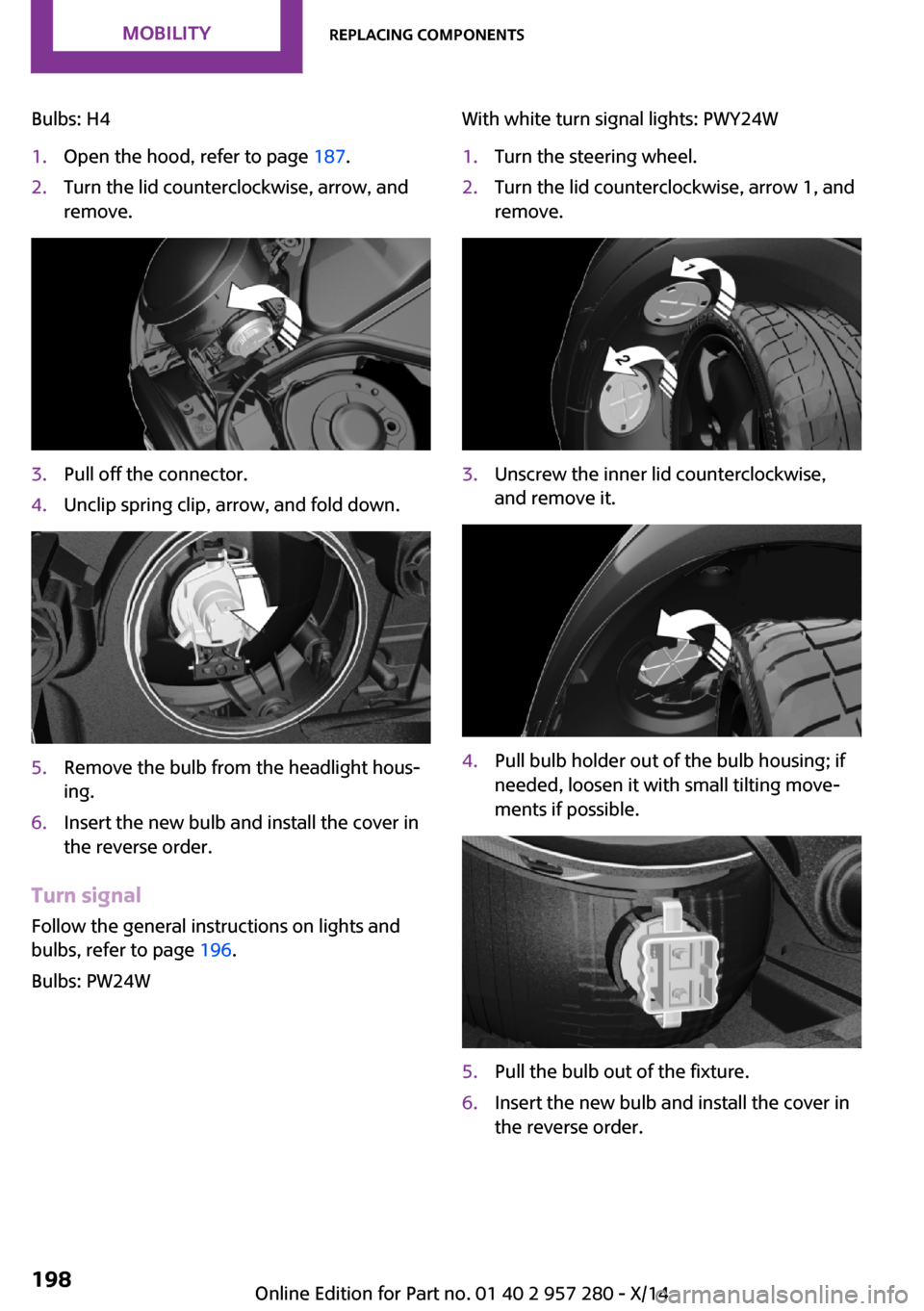
Bulbs: H41.Open the hood, refer to page 187.2.Turn the lid counterclockwise, arrow, and
remove.3.Pull off the connector.4.Unclip spring clip, arrow, and fold down.5.Remove the bulb from the headlight hous‐
ing.6.Insert the new bulb and install the cover in
the reverse order.
Turn signal
Follow the general instructions on lights and
bulbs, refer to page 196.
Bulbs: PW24W
With white turn signal lights: PWY24W1.Turn the steering wheel.2.Turn the lid counterclockwise, arrow 1, and
remove.3.Unscrew the inner lid counterclockwise,
and remove it.4.Pull bulb holder out of the bulb housing; if
needed, loosen it with small tilting move‐
ments if possible.5.Pull the bulb out of the fixture.6.Insert the new bulb and install the cover in
the reverse order.Seite 198MOBILITYReplacing components198
Online Edition for Part no. 01 40 2 957 280 - X/14
Page 203 of 240
LED parking lights/LED fog lightsFollow the general instructions on lights and
bulbs, refer to page 196.
The lights feature LED technology. Contact your
service center in the event of a malfunction.
Parking lights/fog lights/daytime
running lights
Follow the general instructions on lights and
bulbs, refer to page 196.
Bulbs:▷Parking lights for halogen headlights: W5W
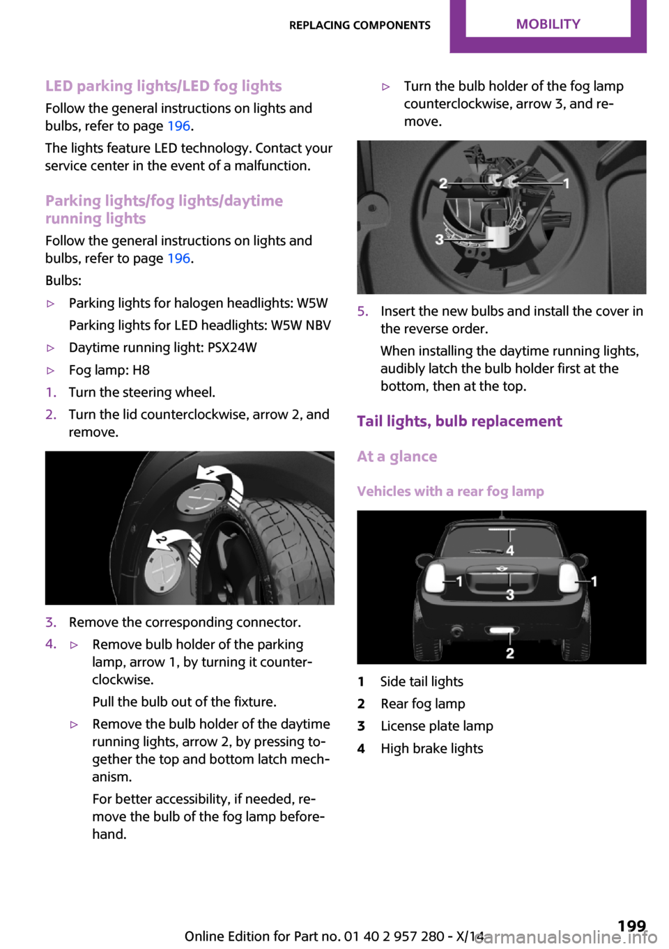
Parking lights for LED headlights: W5W NBV▷Daytime running light: PSX24W▷Fog lamp: H81.Turn the steering wheel.2.Turn the lid counterclockwise, arrow 2, and
remove.3.Remove the corresponding connector.4.▷Remove bulb holder of the parking
lamp, arrow 1, by turning it counter‐
clockwise.
Pull the bulb out of the fixture.▷Remove the bulb holder of the daytime
running lights, arrow 2, by pressing to‐
gether the top and bottom latch mech‐
anism.
For better accessibility, if needed, re‐
move the bulb of the fog lamp before‐
hand.▷Turn the bulb holder of the fog lamp
counterclockwise, arrow 3, and re‐
move.5.Insert the new bulbs and install the cover in
the reverse order.
When installing the daytime running lights,
audibly latch the bulb holder first at the
bottom, then at the top.
Tail lights, bulb replacement
At a glance
Vehicles with a rear fog lamp
1Side tail lights2Rear fog lamp3License plate lamp4High brake lightsSeite 199Replacing componentsMOBILITY199
Online Edition for Part no. 01 40 2 957 280 - X/14
Page 209 of 240
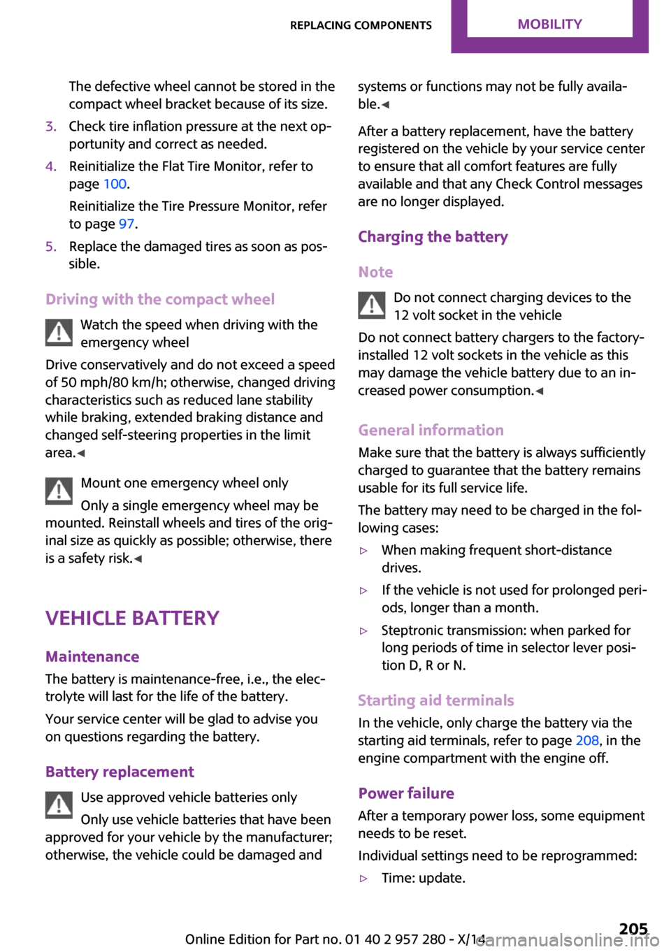
The defective wheel cannot be stored in the
compact wheel bracket because of its size.3.Check tire inflation pressure at the next op‐
portunity and correct as needed.4.Reinitialize the Flat Tire Monitor, refer to
page 100.
Reinitialize the Tire Pressure Monitor, refer
to page 97.5.Replace the damaged tires as soon as pos‐
sible.
Driving with the compact wheel
Watch the speed when driving with the
emergency wheel
Drive conservatively and do not exceed a speed
of 50 mph/80 km/h; otherwise, changed driving
characteristics such as reduced lane stability
while braking, extended braking distance and
changed self-steering properties in the limit
area. ◀
Mount one emergency wheel only
Only a single emergency wheel may be
mounted. Reinstall wheels and tires of the orig‐
inal size as quickly as possible; otherwise, there
is a safety risk. ◀
Vehicle battery Maintenance
The battery is maintenance-free, i.e., the elec‐
trolyte will last for the life of the battery.
Your service center will be glad to advise you
on questions regarding the battery.
Battery replacement Use approved vehicle batteries only
Only use vehicle batteries that have been
approved for your vehicle by the manufacturer;
otherwise, the vehicle could be damaged and
systems or functions may not be fully availa‐
ble. ◀
After a battery replacement, have the battery
registered on the vehicle by your service center
to ensure that all comfort features are fully
available and that any Check Control messages
are no longer displayed.
Charging the battery
Note Do not connect charging devices to the
12 volt socket in the vehicle
Do not connect battery chargers to the factory-
installed 12 volt sockets in the vehicle as this
may damage the vehicle battery due to an in‐
creased power consumption. ◀
General information
Make sure that the battery is always sufficiently
charged to guarantee that the battery remains
usable for its full service life.
The battery may need to be charged in the fol‐
lowing cases:▷When making frequent short-distance
drives.▷If the vehicle is not used for prolonged peri‐
ods, longer than a month.▷Steptronic transmission: when parked for
long periods of time in selector lever posi‐
tion D, R or N.
Starting aid terminals
In the vehicle, only charge the battery via the
starting aid terminals, refer to page 208, in the
engine compartment with the engine off.
Power failure
After a temporary power loss, some equipment
needs to be reset.
Individual settings need to be reprogrammed:
▷Time: update.Seite 205Replacing componentsMOBILITY205
Online Edition for Part no. 01 40 2 957 280 - X/14
Page 214 of 240
▷When the engine is stopped, there is no
power assist. Consequently, more force
needs to be applied when braking and
steering.▷Larger steering wheel movements are re‐
quired.▷The towing vehicle must not be lighter than
the vehicle being towed; otherwise, it will
not be possible to control the vehicle's re‐
sponse.
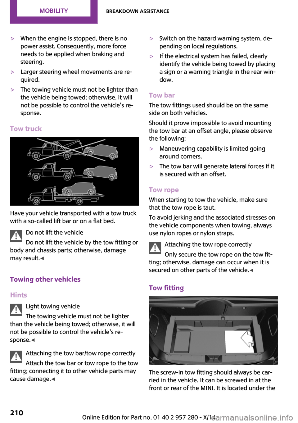
Tow truck
Have your vehicle transported with a tow truck
with a so-called lift bar or on a flat bed.
Do not lift the vehicle
Do not lift the vehicle by the tow fitting or
body and chassis parts; otherwise, damage
may result. ◀
Towing other vehicles
Hints Light towing vehicle
The towing vehicle must not be lighter
than the vehicle being towed; otherwise, it will
not be possible to control the vehicle's re‐ sponse. ◀
Attaching the tow bar/tow rope correctly
Attach the tow bar or tow rope to the tow
fitting; connecting it to other vehicle parts may
cause damage. ◀
▷Switch on the hazard warning system, de‐
pending on local regulations.▷If the electrical system has failed, clearly
identify the vehicle being towed by placing
a sign or a warning triangle in the rear win‐
dow.
Tow bar
The tow fittings used should be on the same
side on both vehicles.
Should it prove impossible to avoid mounting
the tow bar at an offset angle, please observe
the following:
▷Maneuvering capability is limited going
around corners.▷The tow bar will generate lateral forces if it
is secured with an offset.
Tow rope
When starting to tow the vehicle, make sure
that the tow rope is taut.
To avoid jerking and the associated stresses on
the vehicle components when towing, always
use nylon ropes or nylon straps.
Attaching the tow rope correctly
Only secure the tow rope on the tow fit‐
ting; otherwise, damage can occur when it is
secured on other parts of the vehicle. ◀
Tow fitting
The screw-in tow fitting should always be car‐
ried in the vehicle. It can be screwed in at the
front or rear of the MINI. It is located under the
Seite 210MOBILITYBreakdown assistance210
Online Edition for Part no. 01 40 2 957 280 - X/14
Page 230 of 240
Everything from A to ZIndexA
ABS, Antilock Brake Sys‐ tem 109
ACC, Active Cruise Control 113
Acceleration Assistant, refer to Launch Control 71
Activated-charcoal filter 135
Active Cruise Control, ACC 113
Additives, oil 189
Adjustments, seats/head re‐ straints 48
Adjustments, steering wheel 55
After washing vehicle 213
Airbags 93
Airbags, indicator/warning light 95
Air circulation, refer to Recir‐ culated-air mode 131, 134
Air conditioner 130
Air, dehumidifying, refer to Cooling function 131, 134
Air distribution, manual 131, 133
Air flow, air conditioner 131
Air flow, automatic climate control 133
Air pressure, tires 172
Air vents, refer to Ventila‐ tion 135
Alarm system 43
Alarm triggering 43
Alarm, unintentional 44
All around the center con‐ sole 16
All around the roofliner 17
All around the steering wheel 14
All-season tires, refer to Win‐ ter tires 180 Alternating-code hand-held
transmitter 138
Alternative oil types 190
Antifreeze, washer fluid 67
Antilock Brake System, ABS 109
Anti-slip control, refer to DSC 109
Approved axle load 219
Approved engine oils 190
Arrival time 82
Ash tray 141
Assistance, Roadside Assis‐ tance 207
Assistance when driving off 112
Assist system, refer to Intelli‐ gent Safety 102
AUTO intensity 133
Automatic car wash 212
Automatic climate con‐ trol 132
Automatic Curb Monitor 54
Automatic deactivation, front- seat passenger airbags 95
Automatic headlight con‐ trol 89
Automatic locking 42
Automatic recirculated-air control 134
Automatic transmission with Steptronic 68
AUTO program, automatic cli‐ mate control 133
AUTO program, intensity 133
Auto Start/Stop function 62
Average fuel consumption 81
Average speed 82
Axle loads, weights 219 B
Backrest curvature, refer to Lumbar support 49
Band-aids, refer to First aid kit 207
Bar for tow-starting/ towing 210
Battery replacement, vehicle battery 205
Battery, vehicle 205
Belts, safety belts 50
Beverage holder, cu‐ pholder 146
Bonus range, GREEN mode 162
Bottle holder, refer to Cu‐ pholder 146
Brake assistant 109
Brake discs, break-in 152
Brake pads, break-in 152
Braking, hints 153
Breakdown assistance 207
Break-in 152
Brightness of Control Dis‐ play 85
Bug light 197
Bulb replacement 196
Bulb replacement, front 197
Bulb replacement, rear 199
Bulb replacement, side 202
Bulbs and lights 196
Button, RES 115
Button, Start/Stop 60
Bypassing, refer to Jump- starting 207
C
California Proposition 65 Warning 7 Seite 226REFERENCEEverything from A to Z226
Online Edition for Part no. 01 40 2 957 280 - X/14